HEAT EXCHANGER
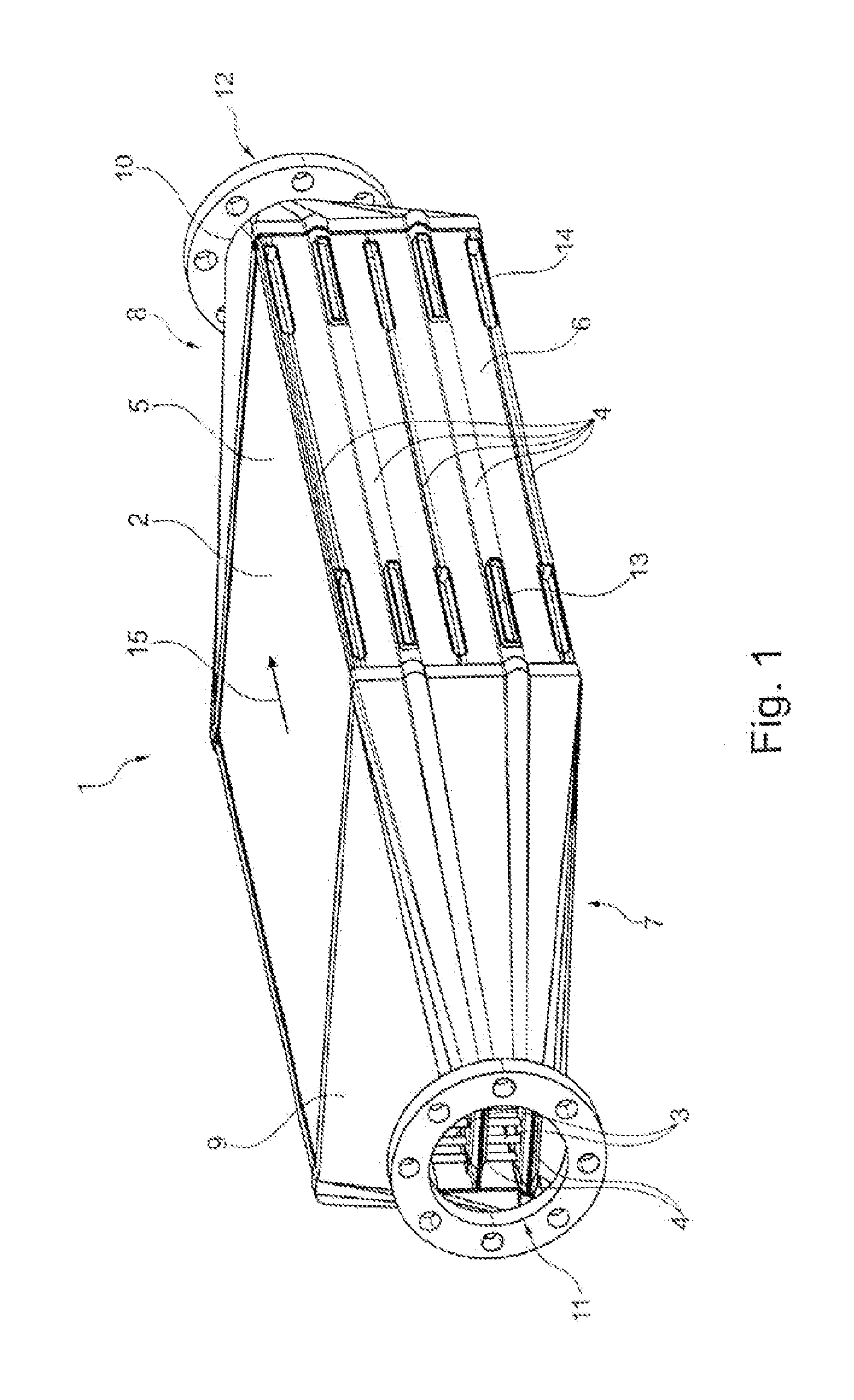
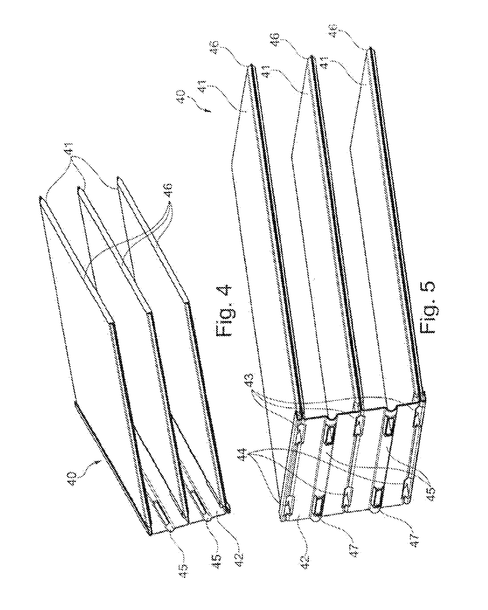
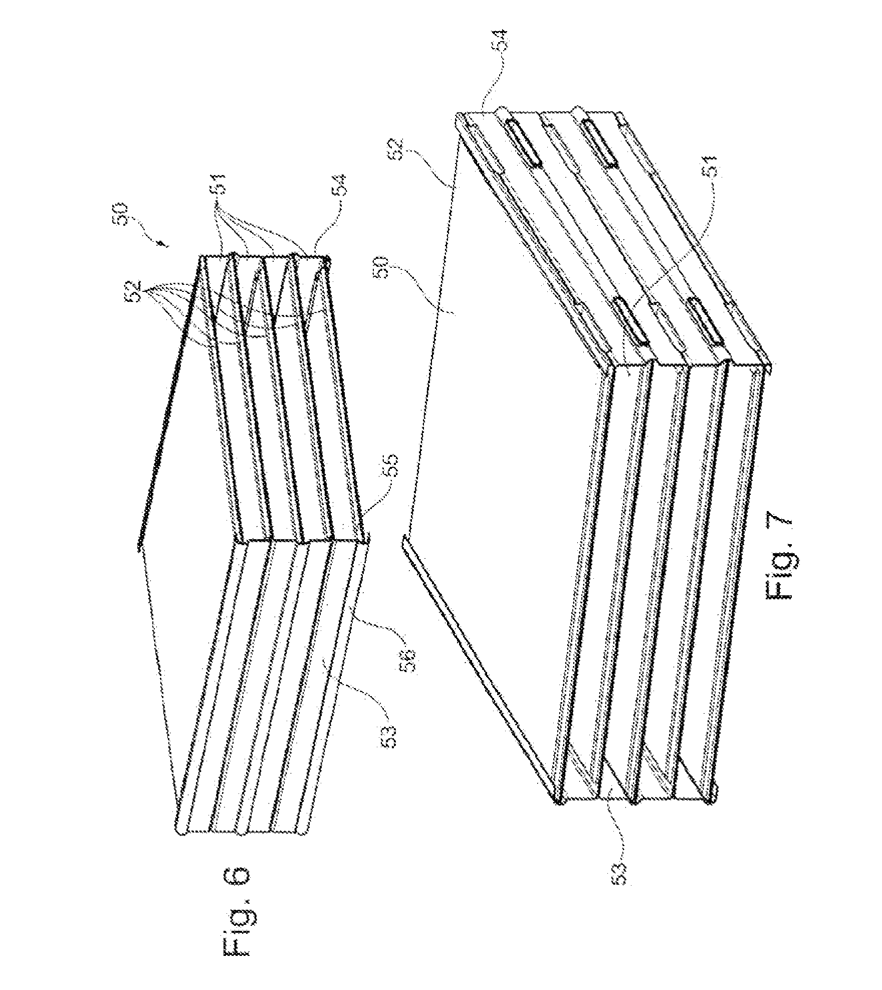
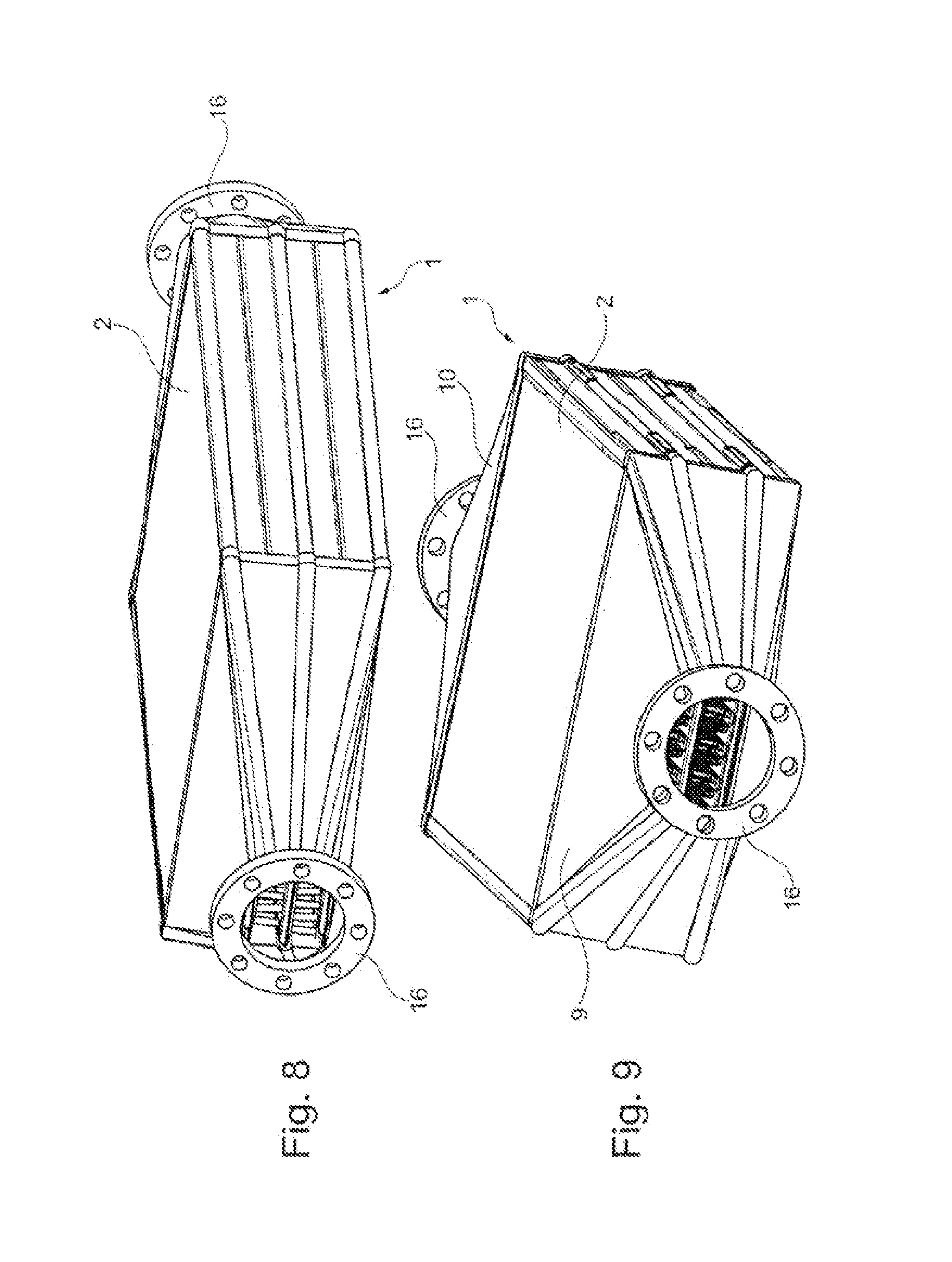
The invention relates to a heat exchanger having a block of first and second flow ducts which are arranged adjacent to one another, wherein the block is designed to be open at an inflow side and at an outflow side of the first flow ducts for the inflow and outflow of a first fluid into and out of the first flow ducts, wherein the second flow ducts have openings for the inflow and outflow of a second fluid, in particular as per the preamble of claim 1. Heat exchangers of the above type are known in the prior art for example for exhaust-gas coolers or charge-air coolers. In this case, exhaust gas or charge air, respectively, is used as first fluid, wherein a liquid coolant is used as second fluid. Here, the alternating arrangement of the first and second flow ducts effects expedient cooling of the first fluid. Heat exchangers of said type are known for example as disk-type heat exchangers or as stacked-disk heat exchangers. In the case of disk-type heat exchangers, pairs of disks are connected to form first fluid ducts, wherein a multiplicity of disk pairs lined up together form, between them, the second fluid ducts. In the case of stacked-disk heat exchangers, identical disks are stacked one on top of the other, with first and second fluid ducts being arranged alternately between the disks. A disadvantage of the disk-type or stacked-disk concepts is the cutting waste produced during the production of the disks. In the case of heat exchangers of tube bundle type of construction, having a tube bundle in which the tubes of the tube bundle are welded into tube plates, the outlay in terms of assembly is relatively high. It is therefore the object of the present invention to provide a heat exchanger as discussed above which can be constructed easily and with reduced usage of material. The problem addressed by the present invention is solved by means of a heat exchanger having the features as per claim 1. An exemplary embodiment of the invention relates to a heat exchanger having a block of first and second flow ducts, wherein the block is designed to be open at an inflow side and at an outflow side of the first flow ducts for the inflow and outflow of a first fluid into and out of the first flow ducts, wherein the second flow ducts have openings for the inflow and outflow of a second fluid, characterized in that the block is composed of a first element and of a second element, the first and the second element each form second flow ducts and a side wall, wherein the elements are joined together such that the two side walls form opposite side walls of the block and the second flow ducts extend between the side walls and form first flow ducts between themselves and the side walls. It is achieved in this way that the provided number of second flow ducts, together with the two side walls, form the block, and the first flow ducts are received between the two second flow ducts. It is also preferably the case that two second flow ducts form the remaining side walls of the block, such that said block is surrounded by a wall on four sides. Said two flow ducts are preferably two second flow ducts situated at the outside. In this way, the entire block is formed by two elements. It may furthermore also be expedient for turbulence-generating inserts also to be placed into the flow ducts. It is also advantageous if the second flow ducts and the side wall of an element are manufactured from one part by stamping and folding. In this case, the element is manufactured, stamped and folded for example from a material strip, such that, between two layers of the material strip, a flow duct the fluid of the first flow duct can flow. The multiplicity of second flow ducts can be formed by way of an encircling embossment and a subsequently produced brazed connection or other seal. It is furthermore expedient if the second flow ducts and the side wall of an element are of comb-like configuration. In this way, a side wall and second flow ducts projecting therefrom can be formed in a straightforward manner. It is also expedient if the second flow ducts of one element engage between the second flow ducts of the other element. In this way, it is achieved that the two side walls are situated opposite one another and the second flow ducts are oriented parallel to one another. It is also expedient if the second flow ducts of one element are supported on the side wall of the respective other element. In this way, sealing of the first flow ducts is achieved, as these are arranged between the second flow ducts. It is furthermore expedient if the side wall of an element has at least one abutment region, or abutment regions, which serve for the abutment of at least one end region, or end regions, of the second flow ducts. Said abutment regions serve for support and secure location before the connection or brazing process, such that a defined position can be realized. It is furthermore expedient if a second flow duct has an inflow and/or outflow opening in a region of its fold. Thus, the flow duct may be stamped in the region of the fold in order to realize an inflow or outflow through the opening thus formed. It is also expedient if a second flow duct has an inflow and/or outflow opening in an end region. It can be achieved in this way that the second flow duct can be supplied with the fluid from the same side as the other second flow ducts which project from the other side wall. It is thus not necessary to provide collecting tanks on both sides. A simple configuration can be realized in this way. It is particularly expedient if a side wall has openings in the abutment region adjacent to openings in the end region of the second flow duct. A supply can thus be provided to the openings in the end regions. It is also expedient if the openings for the inflow and/or outflow of a fluid into or out of the second flow ducts are arranged on a side wall of the block. It is furthermore expedient if the openings for the inflow of a fluid into the second flow ducts are equipped with a manifold with a fluid inlet, and the openings for the outflow of a fluid out of the second flow ducts are equipped with a manifold with a fluid outlet. It is particularly advantageous if the block is equipped, on its inflow side and/or on its outflow side of the first flow ducts, with a manifold with an inflow and/or outflow opening. Advantageous refinements of the present invention are described in the subclaims and in the following description of the figures. Below, the invention will be discussed in more detail on the basis of an exemplary embodiment and with reference to a drawing, in which: A first fluid can enter the manifold 9 through the inflow opening 11, can subsequently pass through the first flow ducts 3, and can exit the heat exchanger 1 via the manifold 10 and the outlet opening 12. Here, the face side 7 forms an inflow side of the first flow ducts 3 of the block 2, wherein the face side 8 forms the outflow side of the first flow ducts 3 of the block 2. At the inflow side and at the outflow side, the first flow ducts 3 are designed to be open for the inflow and outflow of a first fluid into the first flow ducts 3 and out of the first flow ducts 3. It can also be seen in The openings 13, 14, as inflow openings and outflow openings, are arranged one above the other as viewed in a direction perpendicular to the flow direction 15 of the first fluid. Here, the openings 13 are arranged at an end region of the second flow ducts 4 adjacent to the inlet for the first fluid, wherein the openings 14 are arranged in the end region of the second flow ducts 4 adjacent to the outlet for the first fluid. If the second fluid is caused to flow in a countercurrent configuration with respect to the first fluid through the heat exchanger, the openings 14 constitute the inflow opening and the openings 13 constitute the outflow openings. In the case of a co-directional throughflow configuration, the openings would be reversed. The first element 20 is formed from a material strip, said first element having been produced by stamping and folding. The second flow ducts 21 are of double-walled form and are formed by folds in the region of the side wall 22 at 23 and at the end regions 24 of the second flow ducts. The second flow ducts 21 have, at the edge, an embossment 25 such that the top side 26 can be connected at the edge to the underside 27 of the flow duct in order to produce a flow volume within the second flow duct 21. At the end regions 24, the second flow ducts 21 are equipped with the openings 28, 29 in order that a second fluid can flow into the second flow duct 21 and can flow out of the second flow duct 21. The side wall 22 has arched regions 30 which serve as abutment regions for the abutment of end regions of second flow ducts 21. The side walls 22 have, at their end regions, angled ends 31 which serve for the fixing of second flow ducts 21 which project from an opposite side wall to the present side wall. It can also be seen that the manifolds 9, 10 have central inflow and outflow openings 11, 12 which are surrounded by flanges 16 in order that the heat exchanger can be connected to a supply line for exhaust gas or charge air, for example. According to the invention, it is particularly advantageous for stamped dimples or beads to be provided in the first and/or second flow ducts for flow guidance purposes. This can advantageously realize improved cooling performance, reduced temperature peaks in regions with poor throughflow, and/or process improvements, owing to support of the wall regions. This is particularly preferable in the case of an embodiment of the heat exchanger for use with a gaseous first fluid and a liquid second fluid, such as for example an exhaust-gas/coolant cooler, such as an indirect charge-air cooler, in which the charge air is cooled by way of liquid coolant. Furthermore, according to the invention, at least one of the flow ducts may be formed without an inserted turbulence insert. For this purpose, the corresponding flow duct may have a dividing surface, which is of undulating profile, for generating turbulence in the first and/or second fluid ducts. This exemplary embodiment is preferable in the case of the first and second fluid both being liquid, such as is the case for example in an oil/coolant cooler. As an alternative to this, a turbulence insert may be inserted into the first and/or second fluid duct; in particular, a turbulence insert may be provided in the flow duct for the first fluid. This is preferable in the case of a first fluid being gaseous. The heat exchanger is preferably in the form of a cross-current flow or countercurrent flow heat exchanger. It is preferably the case that no collecting tanks are provided for the first fluid. This is a preferred structural form for heat exchangers with a large cross section for the first fluid, in particular for a heat exchanger for components in a cooling module in the incident air flow of the vehicle, such as a coolant cooler, oil cooler, air-conditioning condenser etc. Preferred materials for the heat exchanger are steel or aluminum or an aluminum alloy. As exemplary embodiments for a manifold for the second fluid, it is possible for said manifold to be equipped with an encircling flanged portion in order to increase the abutment surface and, if appropriate, to achieve an improved brazing result and possibly higher strength. A further alternative is a clasping configuration in which the manifold also engages around the folded matrix at the top and at the bottom. In the production method, in order to be positioned on other elements of the heat exchanger, the manifold may also be tacked to said other elements, for example by way of tack welding seams. It is particularly advantageous if both sides are composed of the same, repeating comb-like or loop-like contour, which however differ in terms of different positions of the openings for the first and second fluids. In this case, it is particularly advantageous for the two comb profiles to have an identical structure, wherein said comb profiles may however differ in terms of the number of ducts for second fluid. The flow through the heat exchanger would then be referred to as a Z-shaped flow with an odd number of ducts for the second fluid. It may also be advantageous for an additional base and cover plate to be provided in order to facilitate positive locking between the manifold for the first fluid and the matrix, and in order to realize an increase in strength. According to the invention, the heat exchanger may also be formed by way of so-called one-shot brazing, and may be brazed as a whole together with brackets and other peripheral parts. The invention relates to a heat exchanger comprising a block of first and second flow channels arranged adjacently to one another, said block being designed to be open at one inflow side and at one outflow side of the first flow channels for the inflow and outflow of a first fluid into or out of said first flow channels, and the second flow channels comprising openings for the inflow and outflow of a second fluid, said block consisting of a first element and a second element, each of these forming second flow channels and a side wall, and these elements being joined together such that the two side walls form block side walls which lie opposite one another, said second flow channels extending between these side walls and forming first flow channels between themselves and the side walls. 1. A heat exchanger having a block of first and second flow ducts, wherein the block is designed to be open at an inflow side and at an outflow side of the first flow ducts for the inflow and outflow of a first fluid into and out of the first flow ducts, wherein the second flow ducts have openings for the inflow and outflow of a second fluid, wherein the block is composed of a first element and of a second element, the first and the second element each form second flow ducts and a side wall, wherein the elements are joined together such that the two side walls form opposite side walls of the block and the second flow ducts extend between the side walls and form first flow ducts between themselves and the side walls. 2. The heat exchanger as claimed in 3. The heat exchanger as claimed in 4. The heat exchanger as claimed in 5. The heat exchanger as claimed in 6. The heat exchanger as claimed in 7. The heat exchanger as claimed in 8. The heat exchanger as claimed in 9. The heat exchanger as claimed in 10. The heat exchanger as claimed in 11. The heat exchanger as claimed in 12. The heat exchanger as claimed in TECHNICAL FIELD
PRIOR ART
PRESENTATION OF THE INVENTION, PROBLEM, SOLUTION, ADVANTAGES
BRIEF DESCRIPTION OF THE DRAWINGS
PREFERRED EMBODIMENT OF THE INVENTION