SLIDING MEMBER AND SLIDING BEARING
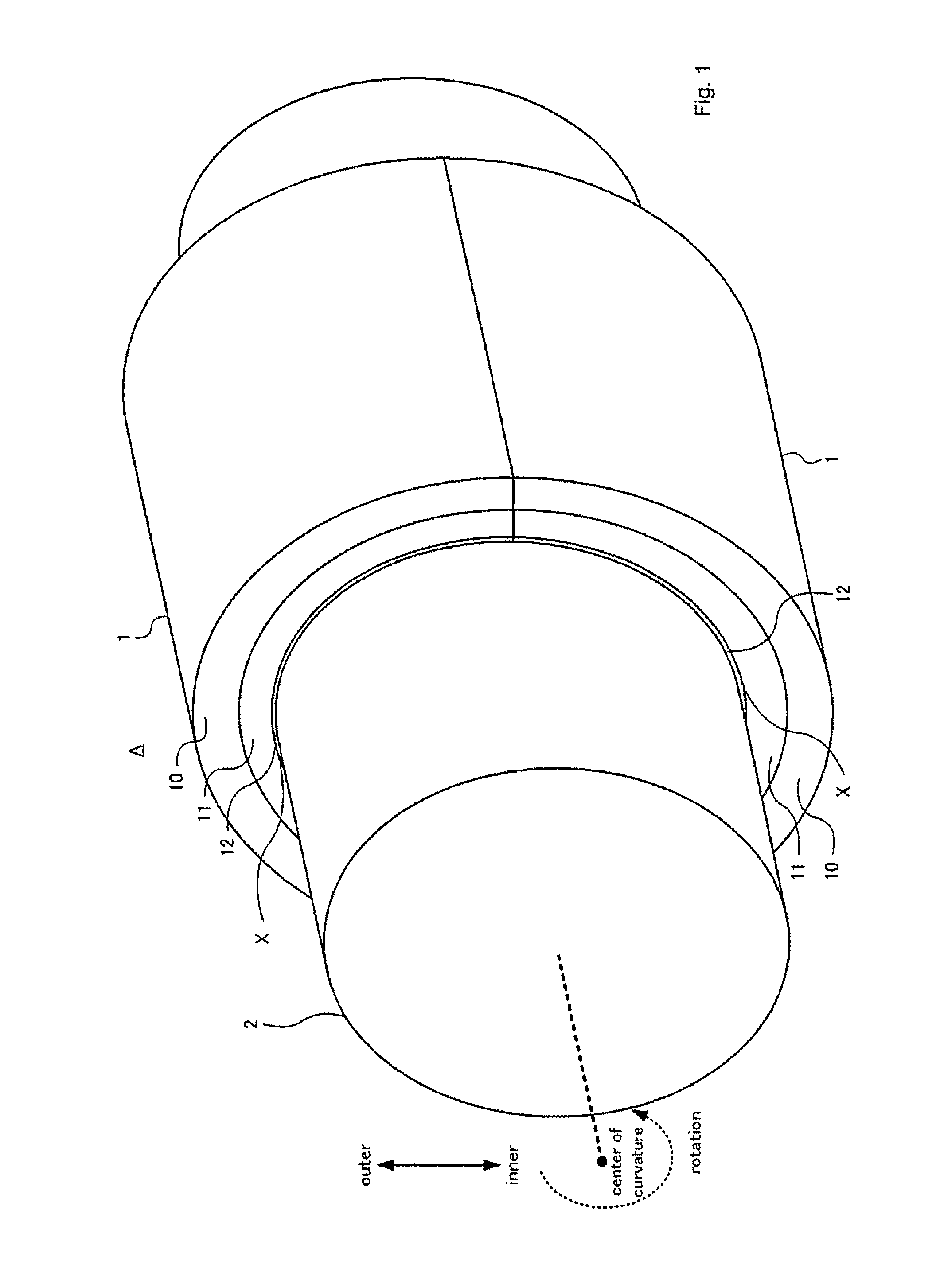
The present invention relates to a sliding member and a sliding bearing whereon a mating member is sliding. A technology comprising forming voids by ultrasonic cleaning a surface of Cu alloy and plating Bi overlay layer on the surface of Cu alloy and the voids, is known (Patent documents JP2009-203504A). Accordingly, the overlay layer can be formed so that the Bi filled in the voids become anchors. [PTL1] JP2009-203504A However, array direction of the crystal grains of Bi filled in voids and Bi of the overlay layer are uniform, because Bi filled in voids and Bi of the overlay layer are continuously grown. That is, there is a problem that grain boundaries of Bi filled in voids and grain boundaries of Bi of the overlay layer continuously connect in a vertical direction for a sliding plane, and fatigue fractures transmit to Cu alloy from the overlay layer along the continuous grain boundaries. The present invention is made in consideration of such a problem, and provides a technology to refrain fatigue fractures from transmitting to a base layer from a soft layer. The present invention discloses a sliding member that includes a base layer that includes soft particles made of a soft material deposited in a matrix and a soft layer made of a soft material. The soft material is softer than the matrix, the soft layer is formed on a surface of the base layer, and a maximum epitaxial index of the sliding member is equal to or less than 10% and greater than 0%. The maximum epitaxial index of the sliding member is a maximum value of all of an epitaxial index of the soft particles at the boundary portion. The epitaxial index of the soft particles at the boundary portion is a ratio of: a portion of a length between a first endpoint of a soft particle and a second endpoint of the soft particle where an edge of the boundary portion is not visible within an area not farther than 1 μm from the length between the first endpoint and the second endpoint, to the length between the first endpoint and the second endpoint. The soft particles deposited in the base layer and existing on a boundary surface between the base layer and the soft layer adhere to the soft layer. That is, the soft material composing the soft particles existing on the boundary surface between the base layer and the soft layer and the soft material composing the soft layer, adhere each other. In this manner, common soft material adheres between the soft particles existing on the boundary surface of the base layer, and the soft layer. In the present invention, the boundary portion between the crystal grains with the unique crystal grain structure (e.g. size and array direction of crystal grains) of the soft particles and the crystal grains with the unique crystal grain structure of the soft layer, is formed, on a boundary surface where the common soft material adheres. Therefore, it is possible to refrain the intergranular fracture arisen in the soft layer from penetrating the boundary surface between the base layer and the soft layer, because the grain boundary of the soft layer and the grain boundary of the soft particles in the base layer can be discontinuous. That is, it is possible to refrain the fatigue fracture arisen in the soft layer from transmitting to the base layer via the soft particles. Further, it is possible to refrain the alloy components other than the soft material included in the soft layer from diffusing to the base layer via the soft particles. Further, the anodic oxidation film of the soft material can be formed on the boundary portion between the crystal grains that have the unique crystal grain structure of the soft particles and the crystal grains that have the unique crystal grain structure of the soft layer. That is, it is possible to prevent the soft materials of the soft layer from being epitaxially grown from the soft particles exposed on the surface of the base layer, by anodic oxidizing the soft particles exposed on the surface of the base layer before laminating the soft layer on the surface of the base layer. That is, it is possible to grow the crystal of the soft material with the crystal grain structure different to that of the soft particles, even on the soft particles exposed on the surface of the base layer. Further, the matrix of the base layer can be Cu alloy and the soft material can be Bi. The conformability can be realized by the soft layer made of Bi, because Bi is softer than Cu alloy. Cu alloy means the alloy including Cu as a main component. The soft particles of Bi can deposit in Cu alloy because Bi does almost not have solid solubility for Cu. However, the matrix of the base layer does not limit to Cu alloy and the material of the matrix can be selected according to circumstances e.g. the hardness of the mating member. Further, materials e.g. Pb as long as softer than the matrix and are able to deposit in the matrix, can be the soft material. FIGS. (2A) and (2B) are schematic cross sectional views of sliding member. FIGS. (3A) and (3B) are photographs of cross sectional views of sliding member. Preferred embodiments of the present invention will be described in the following order. (1-1) Configuration of a sliding member: (1-2) Measuring method: (1-3) Manufacturing method of a sliding member: (1-1) Configuration of a sliding member: The sliding member 1 has a layered structure wherein the back metal 10, the lining 11 and the overlay 12 are laminated in order from a far side of the center of curvature. Therefore, the back metal 10 forms an outermost layer of the sliding member 1 and the overlay 12 is an innermost layer of the sliding member 1. Each of the back metal 10, the lining 11 and the overlay 12 has a constant thickness in a circumferential direction. The thickness of the back metal 10 is 1.3 mm. The thickness of the lining 11 is 0.2 mm. And the thickness of the overlay 12 is 10 μm. A radius of a surface of the overlay 12 facing the center of curvature (an inner radius of the sliding member 1) is 40 mm. In this specification, “the inner side” means a side nearby the center of curvature of the sliding member 1 and “the outer side” means an opposite side to the center of curvature of the sliding member 1. The inner surface of the overlay 12 corresponds to a sliding surface between the sliding member 1 and the mating shaft 2. The back metal 10 is made of steel consisted of 0.15 wt % (weight percentage for the back metal 10) of C (copper), 0.06 wt % of Mn (manganese) and the balance Fe (ferrum). In addition, the back metal 10 can be made of a material that can support a load transmitted from the mating shaft 2 through the lining 11 and the overlay 12. Therefore the back metal 10 can be made of a material other than the steel. The lining 11 is a layer laminated on an inner surface of the back metal 10. The lining 11 corresponds to a base layer of the present invention. The lining 11 is consisted of 10 wt % (weight percentage for the lining 11 of Sn (tin), 8 wt % of Bi (bismuth) and the balance. The balance is consisted of Cu and unavoidable impurities. The unavoidable impurities included in the lining 11 are elements e.g. Mg (magnesium), Ti (titanium), B (boron), Pb (lead) and Cr (chromium). The unavoidable impurities are contaminated when the materials of the lining 11 are refined and/or scraped. Total weight percentage of the unavoidable impurities it less than 1.0 wt %. FIG. (2A) is a schematic cross sectional views of the sliding member 1. In FIG. (2A), the curve of the sliding member 1 is ignored. In the lining 11, Bi particles 11 The average equivalent circle diameter of Bi particles 11 The overlay 12 is a layer laminated on an inner surface of the lining 11. The overlay 12 corresponds to the soft layer of the present invention. The inner surface of the lining 11 corresponds to the boundary surface X between the lining 11 and the overlay 12. The overlay is consisted of Bi and unavoidable impurities. The unavoidable impurities included in the overlay 12 are elements e.g. Sn, Fe and Pb. The unavoidable impurities are impurities contaminated from plating liquid for the overlay 12. In the lining 11, total weight percentage of the unavoidable impurities is not more than 1.0 wt % and the weight percentage of Bi is not less than 99%. The crystal grain structure of Bi in the overlay 12 is determined according to the crystal growth condition of lamination of the overlay 12 on the surface of the lining 11. Consequently, the crystal grain structure of Bi composing Bi particles 11 FIG. (2B) is a schematic view showing the state that the fatigue fracture D is arisen in the overlay 12. As shown in FIG. (2B), even if fatigue fracture D arisen in the overlay 12, it is possible to refrain the fatigue fracture D from penetrating the boundary portion Y between Bi particles 11 (1-2) Measuring method: The measurement values mentioned in the embodiment were measured by methods explained hereinafter. The masses of atoms included in the layers of the sliding member 1 were measured by an ICP (Inductively Coupled Plasma) atomic emission spectrometry analyzer (ICPS-8100 made by SHIMADZU CORPORATION). The average equivalent circle diameter of Bi particles 11 Next, the images of Bi particles 11 The boundary portion Y between Bi crystal grains that have the unique crystal grain structure of the soft particles 11 In addition, within the line segment L the portion where edges exist in an area not farther than 1 μpm and portions B (arrow) of the line segment L whose edge did not exist in the area not farther than 1 μm were detected. The epitaxial index was calculated by dividing the length of the portions B by the length of the line segment L. Further, the epitaxial index of each of Bi particles 11 (1-3) Manufacturing method of a sliding member: In the beginning, a low carbon steel flat plate whose thickness was same as the thickness of the back metal 10 was prepared. Next, the powder of the materials for the lining 11 was scattered on the flat plate made of the low carbon steel. Concretely, Cu powder, Bi powder and Sn powder were scattered on the low carbon steel flat plate to be same weight ratio as the weight ratio of the components of abovementioned lining 11. As long as the weight ratio of the components of the lining 11 can be satisfied, powder of alloy e.g. Cu—Bi and Cu—Sn can be scattered on the low carbon steel flat plate. The particle diameter of the powder was regulated to be not larger than 150 μm by a test sieve (JIS Z8801). Next, the low carbon steel flat plate and the powder scattered on the low carbon steel flat plate were sintered. The sinter was performed in inert atmosphere and the sintering temperature was set to the range of 700 to 1000° C. Cooling was performed after sinter. The Cu alloy layer was formed on the low carbon steel flat plate after completion of the cooling. The soft Bi particles 11 Next, the Cu alloy layer formed on the low carbon steel flat plate was processed by grinding. Then, the grinding depth was controlled to make the thickness of the Cu alloy layer formed on the low carbon steel flat plate same as the thickness of the lining 11. The grinding was performed by the lathe on which is set the cutting tool made of the abrasive e.g. sintered diamonds. The surface of the lining 11 after grinding was the boundary surface X between the lining 11 and the overlay 12. Next, the oxide films were formed on the surfaces of Bi particles 11 Next, the overlay 12 was formed by laminating Bi as the soft material with thickness of 10 μm on the anodized surface of the lining 11, by the electroplating. The procedure of the electroplating was as follows. First, the degreasing of the anodized surface of the lining 11 was rinsed with water. Further, unnecessary oxides on the surface of the lining 11 were removed by pickling. After that, the surface of the lining 11 was rinsed with water again. After completion of abovementioned pretreatments, the electroplating was performed by supplying current to the surface of the lining 11 immersed in the plating liquid. The composition of the plating liquid included Bi with density range of 10 to 50 g/L, the organic sulfonic acid with density range of 25 to 100 g/L and additive agents with density range of 0.5 to 50 g/L. The temperature of the plating liquid was 25° C. Further, the current supplied to the surface of the lining 11 was direct current and the current density of the direct current was in the range of 0.5 to 5.0 A/dm2. By performing the electroplating as remarked above, the overlay 12 could be laminated with refraining Bi from being epitaxially growing from Bi particles 11 The sliding member 1 composing the sliding bearing A that supports the crankshaft for the engine was exemplary shown in the above embodiment, the sliding bearing A for other use can be made of the sliding member 1 of the present invention. For example, gear bushes for transmission, piston bushes and boss bushes can be made of the sliding member 1. Needless to say, the sliding member 1 can be parts whereon any mating members other than shafts are sliding. The matrix of the lining 11 does not limit to Cu alloy, the material of the matrix can be selected according to the hardness of the mating shaft 2. Further, materials e.g. Pb, Sn, In (indium) that are softer than the matrix and are able to deposit in the matrix, can be the soft material. And it is not necessarily that the oxide films are formed on the boundary surface X, for example, the epitaxial growth of Bi from Bi particles 11 1:sliding member, 2:mating shaft, 10:back metal, 11:lining, 11 A sliding member includes a base layer that includes soft particles made of a soft material deposited in a matrix and a soft layer made of a soft material. The soft material is softer than the matrix, the soft layer is formed on a surface of the base layer, and a maximum epitaxial index of the soft particles as the boundary portion of the sliding member is equal to or less than 10% and greater than 0%. The epitaxial index of a soft particle at the boundary portion is a ratio of: a portion of a length between a first endpoint and a second endpoint of a soft particle where an edge of the boundary portion is not visible within an area less than 1 μm from the length between the first endpoint and the second endpoint, to the length between the first endpoint and the second endpoint. 1. A sliding member, comprising:
a base layer comprising soft particles made of a soft material deposited in a matrix; and a soft layer made of a soft material, wherein the soft material is softer than the matrix, wherein the soft layer is formed on a surface of the base layer, wherein a maximum epitaxial index of the sliding member is equal to or less than 10% and greater than 0%, wherein the maximum epitaxial index of the sliding member is a maximum value of all of an epitaxial index of the soft particles at the boundary portion, and wherein the epitaxial index of the soft particles at the boundary portion is a ratio of:
a portion of a length between a first endpoint of a soft particle and a second endpoint of the soft particle where an edge of the boundary portion is not visible within an area not farther than 1 μm from the length between the first endpoint and the second endpoint, to the length between the first endpoint and the second endpoint. 2. The sliding member according to 3. The sliding member according to 4. The sliding member according to 5. The sliding member according to 6. A sliding bearing, comprising:
a base layer comprising soft particles made of a soft material deposited in a matrix; and a soft layer made of a soft material, wherein the soft material is softer than the matrix, wherein the soft layer is formed on a surface of the base layer, wherein a maximum epitaxial index of the sliding member is equal to or less than 10% and greater than 0%, wherein the maximum epitaxial index of the sliding member is a maximum value of all of an epitaxial index of the soft particles at the boundary portion, and wherein the epitaxial index of the soft particles at the boundary portion is a ratio of:
a portion of a length between a first endpoint of a soft particle and a second endpoint of the soft particle where an edge of the boundary portion is not visible within an area not farther than 1 μm from the length between the first endpoint and the second endpoint, to the length between the first endpoint and the second endpoint. 7. The sliding bearing according to 8. The sliding bearing according to 9. The sliding bearing according to 10. The sliding bearing according to 11. The sliding member according to 12. The sliding bearing according to TECHNICAL FIELD
BACKGROUND ART
CITATION LIST
Patent Literature
SUMMARY OF THE INVENTION
Technical Problem
Solution to Problem
BRIEF DESCRIPTION OF THE DRAWINGS
DESCRIPTION OF EMBODIMENT
(1) First Embodiment
(2) Other Embodiment
(1) First Embodiment
(2) Other Embodiment
DESCRIPTION OF THE REFERENCE NUMERALS