EARTHQUAKE RESISTING DOOR
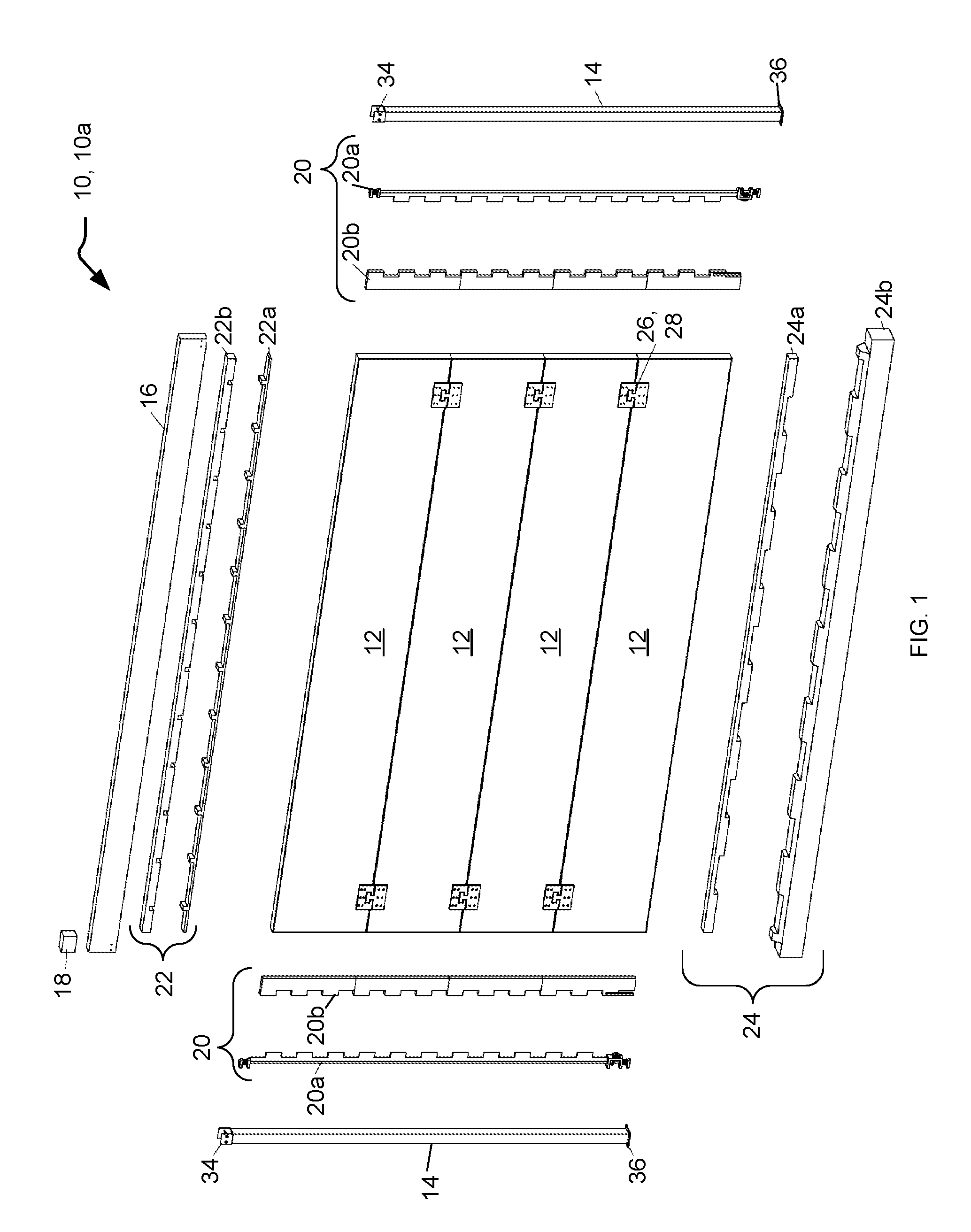
This application claims the benefit of U.S. Provisional Application No. 62/138,147, filed Mar. 25, 2015, and is a continuation-in-part of U.S. application Ser. No. 15/081,835, filed Mar. 25, 2016, hereby incorporated by reference in their entirety. Not applicable. Not applicable. Not applicable. Lateral load resisting shear walls and frames have been used since beginning of the last century to resist those components of force induced in a building by an earthquake, winds, and similar loads. All current system used in resisting these lateral loads are physically fixed in place and therefore cannot be used in the front of a door, garage, or other opening at the exterior or within a building as they will obstruct access or flow into and out of the building by people, vehicles, or other equipment; will not allow for the passage of air, water, or other elements, or will obstruct sound and visibility. In particular, natural events causing a lateral load on the building, such as earthquake, are transient in nature. That is, they occur rarely and randomly and for a short period time over the life of the building. Additionally, opening at the exterior of a building, such as garage doors, are typically in a closed position most of the time. Systems used to resist lateral loads (loads parallel to ground, 90 degrees from gravity) such as seismic forces, wind, tornados, and others are usually resisted by walls, space frames, and braced frames. However, a lot of the time a floor plan does not allow for installation of a wall or braced frame because of the obstruction that these will cause in an opening such as a garage opening, store front, open floor areas, etc. Accordingly, what is needed are improved systems to allow doors, screens, and panels be installed that will provide lateral resistance. Accordingly, it is an object of the present invention to provide an earthquake resisting door. Briefly, one preferred embodiment of the present invention is an earthquake resisting door having an open position and a closed position. The door includes one or more door panels, and end posts located at the left and right sides of the door panels. The door also includes side locking mechanisms having male and female parts. The side locking mechanisms are located between each end post and adjacent door panels, such that the male and female parts inter-lock when the door is in the closed position. The door also includes a top locking mechanism, also having male and female parts. The top locking mechanism is located above the top most door panel, such that the male and female parts inter-lock when the door is in the closed position. And the door includes a bottom locking mechanism. The bottom locking mechanism is located below the bottom most door panel, such that the male and female parts inter-lock when the door is in the closed position. These and other objects and advantages of the present invention will become clear to those skilled in the art in view of the description of the best presently known mode of carrying out the invention and the industrial applicability of the preferred embodiment as described herein and as illustrated in the figures of the drawings. The purposes and advantages of the present invention will be apparent from the following detailed description in conjunction with the appended figures of drawings in which: In the various figures of the drawings, like references are used to denote like or similar elements or steps. A preferred embodiment of the present invention is an earthquake resisting door. As illustrated in the various drawings herein, and particularly in the views of The Earthquake Resisting Door is an earthquake resisting system that can help to resist earthquake loads when it is locked in place. The door can be of any type, roll up, roll down, sliding, lift/flip, split, folding, etc. The present system is used to resist lateral loads (loads parallel to the ground, i.e., 90 degrees from gravity) such as seismic, wind, tornado and others that are usually resisted by wall, space frames, and braced frames. A lot of the time floor plans do not allow installation of walls and braced frames where needed because of the obstruction that these cause in the openings, such as garage openings, store fronts, and open floor areas. The purpose of this invention is to allow doors, screens, and panels be installed and to provided lateral resistance in the way now described. The locking systems, described below, are suitable for use with doors involving three separate concepts. In most single garage houses, the doors are closed more than 99 percent of the time. These garage doors are designed to be engaged with the frames on the top and the two sides as well as the foundation and slab below, to provide lateral support. The possibility of the door not being in the closed position at the time of an earthquake is small. These doors are design to be closed quickly as soon as a certain level of motion is detected. These doors can be used in open front stores or when another method is not considered desirable. A sliding door works in cases when multiple bays of openings are available in parallel, such as in front of a multi-parking apartment structure. In the open position the door slides over, behind or in front of, an adjacent bay that is in the closed position. This is called a temporary position. When one of the doors are open (in a temporary position) the other doors are kept in the close position and provide lateral resistance. Also, if necessary, sliding doors can be designed to provide lateral resistance in a temporary position by having the door engaged with the structure at the top and the foundation at the bottom. 1. A locking mechanism between the various door parts and the side tracks and the foundation or slab. 2. Self-contained limited uplift resisting end posts. 3. A fast acting door that shoots into place in less than 2 seconds in an earthquake. 4. Door panels made of wood or steel, or any other material that can act as a shear wall and/or brace frame. 5. Segmented panels that can be designed into a roll-up or folding panel. The segments interlock to create one solid wall or arrangement of segments that create brace frame action. 6. An inter-locking mechanism that engages adjacent leaves of a door in a casement arrangement and creates one panel. The locking system can consist of any of these: A) A series of prods, anchors, shear keys, or gears that, in the closed position, either automatically fall into matching slot or holes in the end post, the top tracks, or the bottom tracks, e.g., for top and bottom connection of the roll up type door. B) A series rotating metal bars (tracks) with prods or shear keys connected to gears. The gears are design to translate opening and closing movement of the door to rotating of metal bars (tracks) and its longitudinal axis. In closed position the prods or shear keys fall and intrude to matching slot or holes in the door panel and interlock to transfer the loads (for the roll up, tillup, and fold up type doors). A similar mechanism, but with a cylindrical gear, is used to rotate top and bottom metal bars into matching slots or holes in the top track and bottom track. C) A locking system can also be actuated through a magnetic system or be actuated with an electrical signal, releasing the door interlocking system in the open door position but which is fail-safe in the closed door position. The main concept of the invention is a shear or brace panel that opens in a different manner to provide access, but in final closed position or resting position works as an integrated shear wall or braced panel to transfer any shear load and associated overturning moments from the floor above to the floor below. 1) Interlocks with the headers or floor above to collect lateral loads. 2) Transfers the shear load within the body or panel to the floor below. 3) The panel can be of one single panel, such as a tilt-up model, or a multiple segmented panel. 4) In a segmented panel the shear is transferred from one panel to the next by connectors that allow for spatial movement of the panels yet interconnects them to transfer the shear as well as upward and downward loads caused by overturning. 5) The panel is connected to the floor below with an interlocking system that can be a shear key, magnetic, interlocking rod, or bearing or bottom chord connected to the end post or bearing pedestal. 6) In addition to, or in combination with interlocking system, the shear from the bottom of the lowest panel can be transferred to an end an post in a load bearing manner. 7) The upward or downward load of the panel or segmented panel can be achieved with the interlocking system. 8) In-addition to the interlocking system, the uplift transfer can be achieved by load bearing on the end of a top panel on a header. Then the header transfers that load to an end post and the end post transfers the load to the floor below. The roll up door 10 The door panels 12 are main shear load resisting elements. The door panel 12 can be made of metal in a backing grid 38 ( Each segment of a door panel 12 is interconnected on the front or back with a rotating joint 40 that allows for rotation and for transfer of shear with nailing, screwing, or welding of rotating joints to adjoining door panels 12. The door panels 12 are also inter-connected at each end with the inter-panel locking mechanism 26, 28, which is capable of large rotations and yet also able to transfer both shear and uplift from one door panel 12 to the next. The top header 16 is connected to a door panel 12 with the top locking mechanism 22, 22 The upward or downward load of the door panel 12, or segmented panels, is achieved with the side locking mechanisms 20, 20 The motion detector 18 can be a commercially available unit that can be installed over the top header 16, to signal closure of the roll up door 10 The strength of the frame (backing grid 38), its infill and plywood, the end posts 14, the top header 16, and all connectors and the locking system are adjusted based on the seismic load and dimensions (e.g., height and width) of the roll up door 10 The tilt up door 10 The sliding door 10 The assembly consists of one single door panel 62, a top header 64, end posts 66 (one at each end connected to the foundation or floor below), a top track 68 that allows the sliding door 60 to slide (in this example applied to top of the wall), top and bottom locking mechanisms 72, 74, and uplift load bearing applied at each end to the top of the sliding door 10 The door panel 62 is the main shear load resisting element. The door panel 62 is made of wood or steel shear walls (typically consisting of top and bottom plates with interior studs spaced at 16 or 24 inches on center) and shear resistance is provided by plywood, OSB, or metal sheeting applied to the studs. The door panel 62 can also be X-braced or use any other bracing system (not shown) The top track 68 is connected to the top header 64 with screws, and door roller and hanging mechanisms 70 are supported from the top track 68. The door roller and hanging mechanisms 70 are attached to the top of the sliding door 10 The top locking mechanism 72, between the top track 68 and the door panel 62, transfers lateral (shear) force from the top track 68 to the top of the door panel 62. The top locking mechanism 72 consists of a metal strip of full length track (may be used in each side if the shear load is high). This strip is screwed or welded to the side of top track 68. It has a jagged edge that interlocks with the strip that is connected to the top of the sliding door 10 The door panel 62 is interlocked with the foundation or floor below in the same way. When the door is installed over a garage floor, a high strength interlocking strip is laid at the time of foundation construction with anchors that are embedded into the footing (the bottom locking mechanism 74). The interlocking strip projects above the top of the foundation slab about ½ inch and provides a load bearing surface for the jagged edge of the door bottom locking strip (each hub provides a load bearing surface). If needed, the strip can be grooved at the center to provide a bottom track. When the sliding door 10 The upward load due to overturning of the door panel 62 is resisted by transferring the upward force to the header with a load bearing mechanism. The top header 64 transfers the upward forces it receives to an end post 66 via a post cap (track support 80). The end post 66 transfers uplift loads to the foundation and completes the load path. The mechanism for engaging the locking systems for the vertical fold up door 10 A horizontal fold up door is the same as the vertical fold up door 10 While various embodiments have been described above, it should be understood that they have been presented by way of example only, and that the breadth and scope of the invention should not be limited by any of the above described exemplary embodiments, but should instead be defined only in accordance with the following claims and their equivalents. An earthquake resisting door has locking mechanisms between the door panel top, sides, and the bottom foundation. Included are self-contained limited uplift resisting end posts, one or more door panels made of wood, steel, or other suitable material that can act as a shear wall or brace frame, and segmented door panels that can be designed for roll-up or folding. The segments interlock to create one solid wall or arrangement of segments that creates brace frame action. An inter-locking mechanism engages adjacent door leaves in a casement arrangement and creates one panel. 1. An earthquake resisting door having an open position and a closed position, the door comprising:
at least one door panel; end posts located at left and right sides of said at least one door panel; side locking mechanisms having male and female parts, a said side locking mechanism located between each said end post and a said at least one door panel, and wherein male and female parts of side locking mechanisms inter-lock when the door is in the closed position; a top locking mechanism having male and female parts, said top locking mechanism located above a top most said at least one door panel, and wherein male and female parts of top locking mechanism inter-locks when the door is in the closed position; and a bottom locking mechanism having male and female parts, said bottom locking mechanism located below a bottom most said at least one door panel, and wherein male and female parts of bottom locking mechanism inter-locks when the door is in the closed position. 2. The door of 3. The door of 4. The door of 5. The door of 6. The door of 7. The door of 8. The door of 9. The door of 10. The door of 11. The door of 12. The door of 13. The door of 14. The door of 15. The door of 16. An earthquake resisting door having an open position and a closed position, the door comprising:
at least one door panel; end posts located at left and right sides of the door; a top track and a door roller and hanging mechanism which hangs from said top track and connects to the top of said at least one door panel, such that the door is a sliding type door; a top locking mechanism having male and female parts, said top locking mechanism located above a top most said at least one door panel, and wherein male and female parts of top locking mechanism inter-locks when the door is in the closed position; and a bottom locking mechanism having male and female parts, said bottom locking mechanism located below a bottom most said at least one door panel, and wherein male and female parts of bottom locking mechanism inter-locks when the door is in the closed position.CROSS-REFERENCE TO RELATED APPLICATIONS
STATEMENT REGARDING FEDERALLY SPONSORED RESEARCH OR DEVELOPMENT
THE NAMES OF THE PARTIES TO A JOINT RESEARCH AGREEMENT
INCORPORATION-BY-REFERENCE OF MATERIAL SUBMITTED ON A COMPACT DISC
BACKGROUND OF THE INVENTION
BRIEF SUMMARY OF THE INVENTION
BRIEF DESCRIPTION OF THE SEVERAL VIEWS OF THE DRAWING(S)
DETAILED DESCRIPTION OF THE INVENTION
Background
Concept
1) Single Panel (e.g., Tilt Up) and Multi-Panel (e.g., Roll Up and Fold Up) Earthquake Type Doors
2) Fast Acting Motion Actuated Type Doors
3) Sliding Type Doors
Components of the Doors
Locking System
Roll Up Door
Tilt Up Door
Sliding Door
Vertical Fold Up Door
Horizontal Fold-Up Door