Medical Diagnostic Ultrasound Imaging System and Method for Receiving Information from a Server During An Examination of a Patient to Improve Workflow
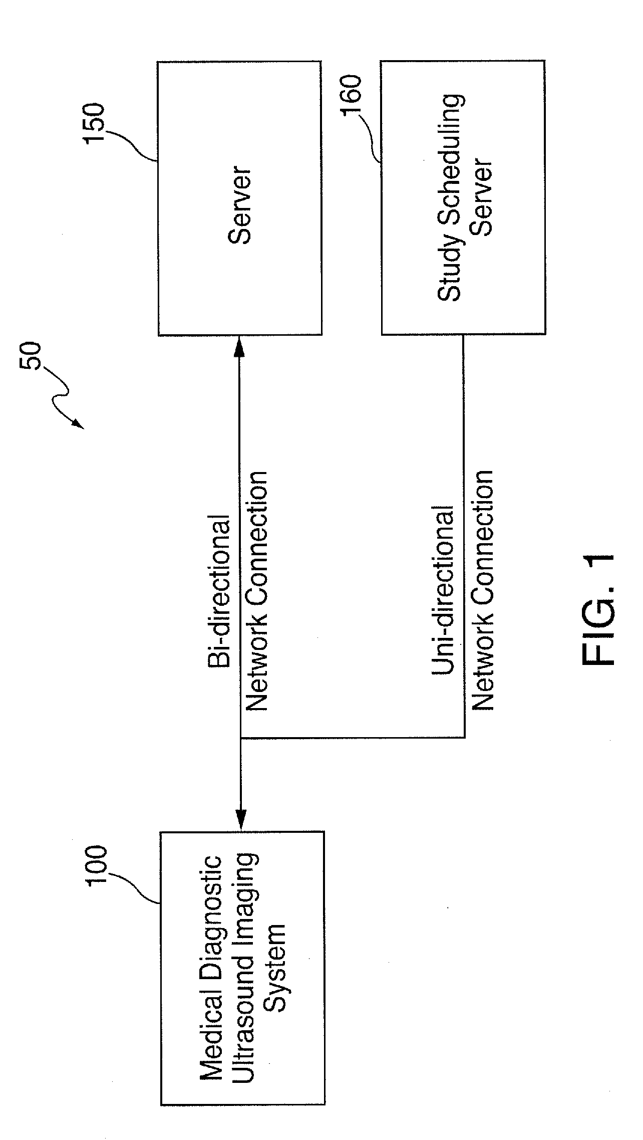
A medical diagnostic ultrasound imaging system is used to conduct an ultrasound examination of a patient. Medical diagnostic ultrasound imaging systems are sometimes connected to a network, and information can be communicated to and from a server in the network before, during, or after the examination. For example, the medical diagnostic ultrasound imaging system can receive a list of scheduled patients from a study scheduling server before the examination, and the medical diagnostic ultrasound imaging system can store captured ultrasound images in an image server before, during, or after an examination. By way of introduction, the following embodiments provide a medical diagnostic ultrasound imaging system and method for receiving information from a server during an examination of a patient to improve workflow. While some prior medical diagnostic ultrasound imaging systems can communicate with a server during an examination, such communication is very limited and does not provide the interactivity that the following embodiments can provide to improve workflow. For example, some prior medical diagnostic ultrasound imaging systems can send captured ultrasound images to a server and can receive an acknowledgment back from the server that the images were received and stored. In contrast, in one embodiment, in response to receiving a captured image or other information about a patient, the server can return information to the medical diagnostic ultrasound imaging system that can improve the sonographer's workflow in conducting the examination. That is, these embodiments can provide a simplified workflow because the sonographer gets information that she otherwise would not get. Also, by having the server provide an intelligent, processed result, these embodiments can make the sonographer perform different acts during the examination of the patient. For example, if the medical diagnostic ultrasound imaging system sends the server a measurement of anatomy under study, and the server can look-up previous measurement(s) of the anatomy, generate a plot showing the current and previous measurements, and send the plot to the medical diagnostic ultrasound imaging system for display to the sonographer. This can help the sonographer decide which images or measurements to take next. As another example, as a sonographer is filling-out a patient study worksheet on the medical diagnostic ultrasound imaging system, the information completed on the worksheet can be sent the server. The server can process the information to determine what remaining sections of the worksheet are relevant and only return the relevant remaining sections to the medical diagnostic ultrasound imaging system. This can improve the sonographer's workflow by eliminating the need for the sonographer to page through irrelevant sections of the worksheet and can also guide the sonographer in which images and measurements to take during the rest of the examination. As another example, the medical diagnostic ultrasound imaging system can provide the server with information about the patient, and, in response to this information, the server can provide the medical diagnostic ultrasound imaging system with images or reports from a prior study of the patient, which the sonographer may find useful in conducting a present examination of the patient. As yet another example, the sonographer can initiate on the ultrasound system an instant message to the radiology reading room asking whether it is OK to release the current patient. The server can send this message (e.g., encrypted) to the active workstations in the radiology reading room. In one embodiment, any physician can “click” on the message, whereupon the server would remove the message from all other workstations and open on the “clicked” workstation the in-progress ultrasound exam showing the sonographer's study worksheet, flagged images, and a window capable of showing all images acquired thus far. The physician can review the images and other information and send an instant message back to the ultrasound machine that the patient can be released or, alternatively, that additional images, tests, or other actions are needed. Of course, these are just examples, and other implementations can be used. Some of these possible implementations are discussed below. Turning now to the drawings, As also used herein, the term “server” can mean a computer program or a device that provides functionality for other programs or devices (“clients”). Servers can provide various functionality (“services”), such as sharing data or resources among one or more clients or performing computation for one or more clients. A client can run on the same device as a server or may connect over a network to a server on a different device. Client-server systems can use a request-response communication technique in which a client sends a request to the server, and the server sends a response back to the client. In some embodiments, a server can be implemented as a physical server or a virtual server. Both can perform similar or identical functions, but their implementations can be different. For example, a physical server can be implemented using hardware (e.g., a CPU, memory, disk storage, network interface, etc), an operating system (e.g., Microsoft Windows Server 2012), and various software that may include, but is not limited to, drivers and application software. The term “physical server” can refer to the hardware, operating system, application, and other software. A virtual server can be implemented using hardware (e.g., a CPU, memory, disk storage, network interface, etc.), virtualizing software that acts to isolate the operating system from the hardware, an operating system, application, and other software. The term virtual server can refer to the operating system, application, and other software and exclude the hardware, or it can refer to both the software and the hardware. A virtual server may be located locally (e.g., in the medical institution's facilities) or “in the cloud” (e.g., when the virtual server is internet-based and provides shared processing resources and other on-demand services). It should be noted that the network configuration 50 in In this embodiment, the controller 230 is configured to control the operation of the medical diagnostic ultrasound imaging system 100. The controller 230 can take the form, for example, of processing circuitry, a microprocessor or processor, logic gates, switches, an application specific integrated circuit (ASIC), a field programmable gate array, a programmable logic controller, an embedded microcontroller, a digital circuit, an analog circuit, combinations thereof, and other now-known or later-developed devices for analyzing and processing data. The controller 230 can be configured with hardware and/or firmware to perform the various functions described below and shown in the flow diagrams. The controller 230 can also execute software to perform these and other functions. For example, the memory 235 (e.g., a computer-readable medium) can store computer-readable program code (e.g., software) executable by a (micro)processor in the controller 230. The software can include a set of instructions that may be executed to cause the controller 230 to perform any one or more of the methods or computer-based functions disclosed herein. In this embodiment, the control panel 250 includes one or more user input devices, such as, but not limited to, a keyboard, a number pad, real or virtual knobs and buttons, a joystick, a mouse or other pointing/selecting device, a touch screen, a camera, a microphone, and a remote control device. One or both of the display devices 260, 270 can take the form of a liquid crystal display (LCD), an organic light emitting diode (OLED), a flat panel display, a solid state display, a cathode ray tube (CRT), a projector, or other now-known or later-developed display device technology for outputting information. In one embodiment, one display device 260 is a relatively-larger display device, and the other display device 270 is a relatively-smaller display device with a touch-sensitive display. Also, instead of two display devices, the medical diagnostic ultrasound imaging system 100 can have one display device or more than two display devices. The network interface 240, which may be part of the controller 230, can be created in software and/or may be a physical connection in hardware. The network interface 240 may be configured to connect with a network and/or external media. The connection with the network may be a physical connection, such as a wired Ethernet connection, and/or may be established wirelessly, such as when a wireless network is used (e.g., a cellular telephone network or an 802.11, 802.16, 802.20, or WiMax network). The network can be a public network, such as the Internet, a private network, such as an intranet, or combinations thereof, and may utilize a variety of networking protocols now available or later developed including, but not limited to, TCP/IP-based networking protocols. In one embodiment, the medical diagnostic ultrasound imaging system 100 acts as a client to the server 150 in a client-server network environment. However, in other embodiments, the medical diagnostic ultrasound imaging system 100 and the server 150 are peer computer systems in a peer-to-peer (or distributed) network environment. In one embodiment, the medical diagnostic ultrasound imaging system 100 and the server 150 communicate using the Digital Imaging and Communications in Medicine (DICOM) standard. The transducer 220 can comprise an array of piezoelectric materials, which can take the form of, for example, a phased linear, linear, curved linear, sector, wide view, single element, 1.5 dimensional, two dimensional, or other type of array of transducer elements. The transducer 220 is configured to convert a waveform from the transmitter 205 to acoustic energy and convert received acoustic energy to electrical signals, which are provided to the receiver 210. The transmitter 205 can comprise digital and/or analog devices for generating the waveform along one or more scan lines, and the receiver 210 can comprise digital and/or analog devices for processing the electrical signals representing echo signals received by the transducer along the one or more scan lines, after the acoustic energy is reflected off of anatomy in the patient. The transmitter 205 and/or receiver 210 can comprise discrete analog circuitry, including amplifiers, filters, digital-to-analog converters, and analog-to-digital converters, for example. In general, during a medical diagnostic ultrasound examination of a patient, a sonographer contacts the transducer 220 with the patient, and the medical diagnostic ultrasound imaging system 100 acquires an ultrasound image in accordance with settings configured in the controller 230 (e.g., as inputted via the control panel 250). In general, the controller 230 causes the transmitter 205 to apply a voltage to the transducer 220 to cause it to vibrate and emit an ultrasonic beam into the portion of the patient's body in contact with the transducer 220. Ultrasonic energy reflected from the patient's body impinges on the transducer 220, and the resulting voltages created by the transducer 220 are received by the receiver 210. The controller 230 processes the sensed voltages to create an ultrasound image and can display the image on one or both of the display devices 260, 270. In addition to being displayed, the ultrasound image can be stored in digital form on the medical diagnostic ultrasound imaging system 100 and/or the network. For example, the sonographer can be given the option of storing an ultrasound image by pressing an “image capture” key on the control panel 250, or, alternatively, the ultrasound image can be automatically stored without user intervention. In this way, a series of images from an ultrasound exam can be stored for later review and analysis. Although not shown in the drawings, the study scheduling server 160 can be implemented in a similar way as the server 150. However, the controller in the study scheduling server 160 can be configured to provide study scheduling information to the medical diagnostic ultrasound imaging system 100. For example, the study scheduling server 160 can send a DICOM modality worklist to the medical diagnostic ultrasound imaging system 100 for display on the display device 260, 270. (While a worklist can be locally stored on the medical diagnostic ultrasound imaging system 100, having the study scheduling server 160 send a DICOM modality worklist to the medical diagnostic ultrasound imaging system 100 can provide department-wide uniformity.) As an alternative to selecting a scheduled study from a DICOM modality worklist and then pressing the “Start Study” button, a sonographer can manually enter (e.g., using the control panel 250) information about a patient into a displayed form on the display device 260, 270. After the examination of the patient begins (e.g., after pressing the “Start Study” button on a DICOM modality worklist or a patient-input form), the sonographer conducts an ultrasound examination of the patient by contacting the transducer 220 to the patient and pressing a real or virtual “Capture” button on the medical diagnostic ultrasound imaging system 100 to generate ultrasound images (still images) or clips (i.e., a sequence of images that are played as a video (e.g., at 16 images/sec.)). During the examination, the sonographer can also enter observations (e.g., using the control panel 250) into a worksheet (e.g., a patient study worksheet) displayed on the medical diagnostic ultrasound imaging system 100. After the sonographer captures all of the needed ultrasound images and completes the appropriate worksheet(s), the sonographer ends the examination by pressing a real or virtual “End Study” button. When the examination ends, the medical diagnostic ultrasound imaging system 100 can store the captured images, completed worksheet, and other information in the medical diagnostic ultrasound imaging system 100 and/or in the network (e.g., in the server 150) or in a storage location connected to the network such as a PACS archive. During the time interval beginning when the “Start Study” button is pressed (or the equivalent) and when the “End Study” button is pressed (or the equivalent), the ultrasound exam may be described as “in progress.” In one embodiment, the ultrasound machine is programmed to send in-progress captured images, measurements, and other information to the server immediately after these items are generated rather than waiting until the entire ultrasound exam is completed to send these items. When the ultrasound machine sends these data and various sonographer inputs to the server while the exam is in progress, the server can provide useful in-progress feedback to the ultrasound machine for use by the sonographer to improve workflow and facilitate the ultrasound study. In other embodiments, the ultrasound machine sends its information to the server after a “Pause Study” button, or the equivalent, is pressed, and the server returns information or other feedback to the ultrasound machine for the sonographer. In these embodiments, the sonographer may need to “Un-Pause,” re-open, or re-start the study in order to perform additional measurements or additional imaging of the patient based on the feedback provided by the server. These other embodiments may provide a less-efficient workflow, but they may allow the ultrasound machine to “batch send” images and data rather than continuously send the images and data as they are acquired. For all of the above embodiments, the communication between the ultrasound machine and the server can be defined as occurring “during an examination” because the patient remains in the ultrasound exam room and the sonographer has the option of adding additional images, measurements, or other data to the patient's ultrasound exam. While some prior medical diagnostic ultrasound imaging systems can communicate with a server during an examination, such communication is very limited. For example, some prior medical diagnostic ultrasound imaging systems can send captured ultrasound images to a server and can receive an acknowledgment back from the server that the images were received and stored. In contrast, the following embodiments provide a level of interactivity between the medical diagnostic ultrasound imaging system and the server that can improve workflow during the examination. More specifically, in this embodiment, the medical diagnostic ultrasound imaging system 100 sends first information about the patient to the server 150 (act 820). The first information can be sent in an encrypted or unencrypted (“in the clear”) form. The “first information about the patient” can take any suitable form and can serve as a way for the server 150 to locate relevant information to send back to the medical diagnostic ultrasound imaging system 100 during the examination and/or can be processed by the server to provide a unique result to the medical diagnostic ultrasound imaging system 100. For example, the “first information about the patient” can be patient-identifying information, such as the patient's name or identifier, as selected from a DICOM modality worklist (see While patient identifier and/or a study identifier will be used in this example to illustrate these embodiments, it should be noted that other forms of “first information the patient” can be used. For example, the first information sent to the server 150 comprises information entered into a patient worksheet, which can be found locally on the medical diagnostic ultrasound imaging system 100 or sent from the server 150 (e.g., the server 150 can select which patient worksheet to send to the medical diagnostic ultrasound imaging system 100 based on the patient identifier and/or study identifier). The information entered into the patient worksheet can take any form, including, but not limited to, a keystroke input, a mouse click input, a selection of a cursor location, a selection of a touch screen location, a measured value, a calculated value, an identification of a value, information about the examination, and information about a protocol step in a diagnostic procedure. As another example, the first information about the patient sent to the server 150 includes one or more of the following: a medical diagnostic ultrasound image, a reference to a medical diagnostic ultrasound image, an “instant message” created by the sonographer, and a sequence of medical diagnostic ultrasound images. As shown from these examples, “first information about the patient” can be information that is derived from the current examination of the patient. Examples of information that is derived from an examination of a patient include, but are not limited to, a medical diagnostic ultrasound image of the patient, a reference to a medical diagnostic ultrasound image of the patient, a sequence (a “clip”) of medical diagnostic ultrasound images of the patient, and a measurement, observation, or finding entered into a worksheet on the medical diagnostic ultrasound imaging system. Of course, these are merely examples, and other information about the patient can be sent to the server 150. The first information can be sent to the server 150 before or after the examination begins or at the exact moment the examination begins. For example, when the first information about the patient is a patient identifier and/or a study identifier obtained from a DICOM modality worklist, the first information about the patient can be send before or after the “Start Study” button is pressed, or simultaneously when the “Start Study” button is pressed. Also, as will be discussed in more detail below, “first information” is not necessarily the first data transmission from the medical diagnostic ultrasound imaging system 100 and the server 150. Further, there can be multiple instances of “first information” sent from the medical diagnostic ultrasound imaging system 100 to the server 150 (and multiple instances of “second information” returned from the server 150 in response) during an examination to provide multiple instances of interactivity. When the server 150 receives the first information about the patient from the medical diagnostic ultrasound imaging system 100, the controller 330 in the server 150 uses the first information to locate or generate “second information” about the patient. For example, the non-volatile memory 320 of the server 150 can store various information about patients in a database or other data structure, and the controller 330 in the server 150 can query the database with the first information about the patient (e.g., the patient identifier and/or study identifier) to locate the relevant second information about the patient. Instead of being stored in the non-volatile memory 320 of the server 150, the second information can be stored in an external storage location, such as an electronic medical record (EMR) system or archive and a picture archive and communication system (PACS) archive. Accordingly, the second information can be accessed by the server 150 from a local or external storage location. As another example, if the first information is a measurement of an anatomy of the patient, the server 150 can process the information to return a chart of current and previous measurements of the anatomy. As yet another example, if the first information is information entered into a patient study worksheet, the server 150 can process the entered worksheet information to generate information customized for the specific protocol being used to guide the sonographer to perform certain steps. Referring back to It should be noted that while After the medical diagnostic ultrasound imaging system 100 receives the second information about the patient from the server 150, the sonographer can view the second information on one or both of the display devices 260, 270 of the medical diagnostic ultrasound imaging system 100 (act 830). If the medical diagnostic ultrasound imaging system 100 has more than two display devices, the second information can be displayed on the additional display devices as well. For example, the second information about the patient received from the server 150 can be simultaneously displayed (e.g., on one or more display devices) with a medical diagnostic ultrasound image generated by the medical diagnostic ultrasound imaging system 100. For example, as shown in The “second information about the patient” can take any suitable form. In one embodiment, the “second information about the patient” is information for use by a sonographer during the examination of the patient. Examples of “second information about the patient” include, but are not limited to, an automatically-selected medical diagnostic ultrasound image of the patient from a prior examination, a drawing made during a prior examination, a prompt to acquire an additional medical diagnostic ultrasound image of the patient, an instant message from a radiologist, a processed image from a current examination of the patient (e.g., such as when artificial intelligence is used to identify and grade a lesion or perform another type of analysis), information from the patient's medical record, the name of the doctor who ordered a prior study, the reason for the prior study, a reading physician's report to the referring physician of the prior study, measured values from the prior study, and trended values of the prior study. As another example, the second information about the patient can be a patient study worksheet tailored to the patient. For example, as a sonographer is filling-out a patient study worksheet on the medical diagnostic ultrasound imaging system, the information completed on the worksheet (the “first information”) can be sent to the server 150. The server 150 can process the first information to determine what remaining sections of the worksheet are relevant and only return the relevant remaining sections (the “second information”) to the medical diagnostic ultrasound imaging system 100. Of course, these are just examples, and other information can be provided. It should be noted that, in some embodiments, the “second information about the patient” is sent after the server 150 sends an acknowledgement of receipt of the “first information about the patient” or some other transmission further to a communications protocol. That is, in some embodiments, the “second information about the patient” is information identified by or generated from the “first information about the patient” and excludes ancillary communication protocol transmissions. The following paragraphs provide examples of different types of “second information about a patient” received from the server 150. It should be noted that these are merely examples and that other implementations can be used. Returning to the drawings, In this example, the selected function was “Report,” so the server 150 retrieves the report for the selected study from the server's database (e.g., stored in RAM 310 or non-volatile memory 320) (act 950). The server 150 then sends the report to the medical diagnostic ultrasound imaging system 100 (act 960), and the medical diagnostic ultrasound imaging system 100 displays the report (act 970). The sonographer then can review the report on the medical diagnostic ultrasound imaging system 100 (act 980) and select another report, if desired (act 990). Flows similar to the one shown in It should be noted that the buttons shown on the screen shot in In addition to providing information about prior data about the patient, the server 150 can provide the medical diagnostic ultrasound imaging system 100 with the patient worksheet based on the first information about the patient sent to the server 150. This example will now be illustrated in conjunction with the flow chart 1200 in While some of the above examples show the server 150 using the first information to look-up stored second information, as noted above, the server 150 can additionally or alternatively process the first information to generate the second information (e.g., the server 150 can provide information that is “unique,” in that it is not previously stored in either the medical diagnostic ultrasound imaging system 100 or the server 150). For example, if the medical diagnostic ultrasound imaging system 100 sends the server 150 a measurement of anatomy under study, and the server 150 can look-up previous measurement(s) of the anatomy, generate a plot showing the current and previous measurements, and send the plot to the medical diagnostic ultrasound imaging system 100 for display to the sonographer. By generating a plot that did not exist before, the server 150 is doing something more than just looking up and returning stored data. That is, the server 150 responds to information about the patient (here, information that is provided by the sonographer and was derived during the current examination of the patient) by processing the information and sending back new information to the ultrasound system 100. This example is illustrated in As another example, as a sonographer is filling-out a patient study worksheet on the medical diagnostic ultrasound imaging system 100, the information completed on the worksheet can be sent to the server 150. The server 150 can process the information to determine what remaining sections of the worksheet are relevant and only return the relevant remaining sections to the medical diagnostic ultrasound imaging system 100. As a related additional example, consider a situation in which the sonographer indicates on a patient study worksheet that there is a cyst on the patient's liver, and that information is sent to the server 150. In response to this information, the server 150 can modify the patient study worksheet to include fields asking for the diameter of the cyst and whether the cyst is clear or contains debris. By receiving this modified worksheet on the ultrasound system 100, the sonographer can be guided on next steps during the examination. As yet another example (see Also, while each diagram discussed above may show a single instance of “first information” sent from the medical diagnostic ultrasound imaging system 100 and a single instance of “second information” sent from the server 150, as noted above, there can be multiple sequences of “first information” sent from the medical diagnostic ultrasound imaging system 100 and multiple sequences of corresponding “second information” sent from the server 150. This provides multiple instances of interactivity that can improve workflow. Also, the various instances of “first information” can be sent at different points during the examination. For example, patient identification information can be sent to the server 150 at the very start of the examination, whereas a measure of anatomy can be sent to the server 150 at some point after the start of the examination. It should also be noted that, in one embodiment, the functionality of interacting with the server 150 is performed by a controller 230 integrated in the medical diagnostic ultrasound imaging system 100. As such, the functionality of interacting with the server 150 is portable with the medical diagnostic ultrasound imaging system 100 and does not require an additional computer local to the medical diagnostic ultrasound imaging system 100 (e.g. a separate network-connected computer in the examination room). Also, although the medical diagnostic ultrasound imaging system 100 interacts with the server 150, it is more than just a substitute for a computer terminal, as a computer terminal does not both generate ultrasound images and accept sonographer measurements made using electronic calipers on the ultrasound machine, sonographer observations, etc. That is, having one system being used to both conduct the examination and interact with the server provides advantages over using two separate devices. There are many alternatives and additions that can be used with these embodiments. For example, there can be instant messaging between the operator of the medical diagnostic ultrasound imaging system and a physician or other person, which can provide an efficient communication mechanism. For example, the operator can enter a message into the medical diagnostic ultrasound imaging system, and the medical diagnostic ultrasound imaging system can send the message to a physician or other person (e.g., via the server or via another communication channel). The message can include text entered by the operator and/or other information, such as, but not limited to, a reference to a patient, a reference to a study, a reference to one or a few medical images previously “tagged” by the sonographer for comment by the physician, or a reference to the entire exam up to this point in time. The physician or other person receiving the message can then send a response back to the operator (e.g., via the server or via another communication channel) that can provide direction or guidance to the sonographer on how to complete the exam. Finally, although a medical diagnostic ultrasound imaging system was used above as an example to illustrate these embodiments, it should be noted that these embodiments can be implemented in other medical diagnostic imaging system. Examples of other imaging modalities include, but are not limited to, computed tomography (CT), magnetic resonance imaging (MRI), computed radiography, magnetic resonance, angioscopy, color flow Doppler, cystoscopy, diaphanography, echocardiography, fluoresosin angiography, laparoscopy, magnetic resonance angiography, positron emission tomography, single-photon emission computed tomography, x-ray angiography, computed tomography, nuclear medicine, biomagnetic imaging, culposcopy, duplex Doppler, digital microscopy, endoscopy, fundoscopy, laser surface scan, magnetic resonance spectroscopy, radiographic imaging, thermography, and radio fluroscopy. Further, the phrase “medical diagnostic” is used herein to distinguish from “therapeutic” systems (e.g., ultrasound system that uses ultrasonic waves to destroy kidney stones). However, it should be noted that these embodiments can be used in therapeutic systems as well. It is intended that the foregoing detailed description be understood as an illustration of selected forms that the invention can take and not as a definition of the invention. It is only the following claims, including all equivalents, that are intended to define the scope of the claimed invention. Finally, it should be noted that any aspect of any of the preferred embodiments described herein can be used alone or in combination with one another. A medical diagnostic ultrasound imaging system and method are provided for receiving information from a server during an examination of a patient to improve workflow. The information provided from the server can be information stored in a server-accessible storage location or generated by the server. The medical diagnostic ultrasound imaging system and server can have bi-directional communication to interact during the examination of the patient. 1. A medical diagnostic ultrasound imaging system with an improved graphical user interface that dynamically displays a worksheet, the medical diagnostic ultrasound imaging system comprising:
at least one transmitter; at least one receiver; a set of user input devices; at least one display device; and a controller in communication with the at least one transmitter, the at least one receiver, the set of user input devices, and the at least one display device, wherein the controller is configured to perform the following after receiving a command signaling a beginning of an examination of a patient but before receiving a command signaling an end of the examination of the patient:
display on the at least one display device an ultrasound image of the patient, wherein the ultrasound image of the patient is generated by the medical diagnostic ultrasound imaging system; and dynamically display a worksheet in a graphical user interface on a same or different one of the at least one display device that displays the ultrasound image of the patient by performing the following, wherein the worksheet comprises a plurality of fields with multiple choice options for sonographer selection, wherein the multiple choice options specify different observations of the ultrasound image of the patient:
display a first section of the worksheet in the graphical user interface; receive a selection of one of the multiple choice options in the worksheet; send the selected multiple choice option to a server, wherein the server stores a plurality of additional sections of the worksheet, some of which are associated with the selected multiple choice option and some of which are not associated with the selected multiple choice option, and wherein the server is configured to identify an additional section of the worksheet that is associated with the selected multiple choice option; receive, from the server, the additional section of the worksheet that is associated with the selected multiple choice option, wherein sections of the worksheet that are not associated with the selected multiple choice option are not received from the server; and display the additional section of the worksheet that is associated with the selected multiple choice option in the graphical user interface; wherein the sending of the selected multiple choice option to the server and the receiving and displaying of the additional section of the worksheet that is associated with the selected multiple choice option occur during the examination of the patient, and wherein such interactivity between the medical diagnostic ultrasound imaging system and the server improves workflow during the examination of the patient by avoiding display of sections of the worksheet in the graphical user interface that are not associated with the selected multiple choice option; wherein the medical diagnostic ultrasound imaging system uses the set of user input devices to receive both a setting used to generate the ultrasound image of the patient and the selection of the multiple choice option. 2. The medical diagnostic ultrasound imaging system of 3. The medical diagnostic ultrasound imaging system of 4. The medical diagnostic ultrasound imaging system of 5. The medical diagnostic ultrasound imaging system of 6. The medical diagnostic ultrasound imaging system of 7. The medical diagnostic ultrasound imaging system of 8. The medical diagnostic ultrasound imaging system of 9. The medical diagnostic ultrasound imaging system of 10. The medical diagnostic ultrasound imaging system of receive second sonographer input in the additional section of the worksheet; send the second sonographer input to the server; receive, from the server, yet another section of the worksheet; and display the yet another section of the worksheet received from the server in the graphical user interface. 11. The medical diagnostic ultrasound imaging system of 12. The medical diagnostic ultrasound imaging system of 13. A method for improving workflow during an examination of a patient using a medical diagnostic ultrasound imaging system with an improved graphical user interface that dynamically displays a worksheet, the method comprising:
performing the following in a medical diagnostic ultrasound imaging system during an ultrasound examination of a patient:
displaying an ultrasound image of the patient on a display device of the medical diagnostic ultrasound imaging system, wherein the ultrasound image of the patient is generated by the medical diagnostic ultrasound imaging system; and dynamically displaying a worksheet in a graphical user interface on a same or different display device that displays the ultrasound image of the patient by performing the following, wherein the worksheet comprises a plurality of fields with multiple choice options for sonographer selection, wherein the multiple choice options specify different observations of the ultrasound image of the patient:
displaying a first section of the worksheet in the graphical user interface; receiving a selection of one of the multiple choice options in the worksheet, sending the selected multiple choice option to a server, wherein the server stores a plurality of additional sections of the worksheet, some of which are associated with the selected multiple choice option and some of which are not associated with the selected multiple choice option, and wherein the server is configured to identify an additional section of the worksheet that is associated with the selected multiple choice option; receiving, from the server, the additional section of the worksheet that is associated with the selected multiple choice option, wherein sections of the worksheet that are not associated with the selected multiple choice option are not received from the server; and displaying the additional section of the worksheet that is associated with the selected multiple choice option in the graphical user interface; wherein such interactivity between the medical diagnostic ultrasound imaging system and the server improves workflow during the examination of the patient by avoiding display of sections of the worksheet in the graphical user interface that are not associated with the selected multiple choice option. 14. The method of 15. The method of 16. The method of 17. The method of sending an instant message to a person remote from the medical diagnostic ultrasound imaging system; and receiving an instant message from the person remote from the medical diagnostic ultrasound imaging system. 18. The method of 19. The method of 20. The method of 21. The method of 22. The method of 23-27. (canceled) 28. The medical diagnostic ultrasound imaging system of 29. The medical diagnostic ultrasound imaging system of 30. The method of BACKGROUND
BRIEF DESCRIPTION OF THE DRAWINGS
DETAILED DESCRIPTION