CONTROL DEVICE AND CONTROL METHOD FOR VEHICLE DRIVE MECHANISM
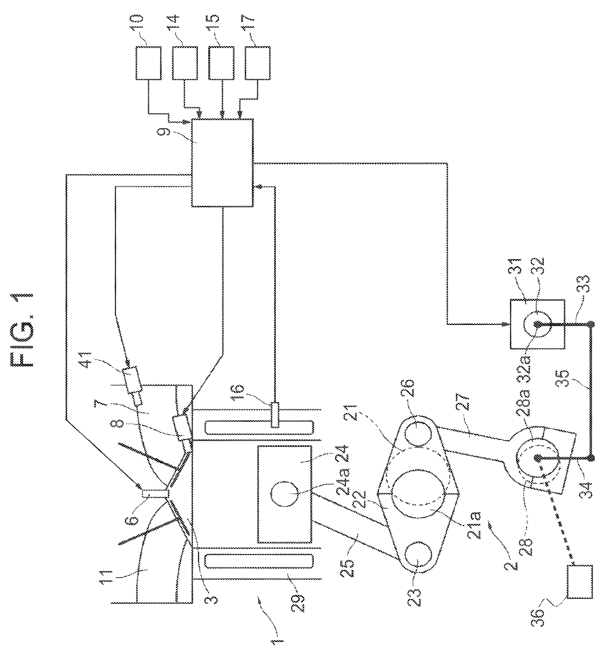
This application is a continuation of U.S. application Ser. No. 16/161,635, filed Oct. 16, 2018, which is a continuation of U.S. application Ser. No. 15/555,707, filed Sep. 5, 2017, which is a 371 of International Application No. PCT/JP2016/056809, filed Mar. 4, 2016, which claims priority from Japanese Patent Application No. 2015-043516, filed Mar. 5, 2015, the disclosures of which are expressly incorporated by reference herein. The present invention relates to a control device and control method for a vehicle drive mechanism, and in particular, relates to a technique for identifying a position of a moving body having a movability range with two ends, each end defined by a stopper. Patent Document 1 discloses a variable compression ratio mechanism capable of changing an engine compression ratio by causing an actuator to change a rotation position of a control shaft so as to change at least one of the top dead center position and the bottom dead center position of pistons in an internal combustion engine. Patent Document 2 discloses a control device for an electric power steering apparatus, including a rack end determination unit for determining whether a steering wheel comes close to a rack end, or a steering limit determination unit for determining whether the steering wheel has reached a steering limit. The control device limits an electric current command value when the steering wheel has come close to the rack end or has reached the steering limit, and applies an electromagnetic brake to a motor at a timing when the electric current command value thus limited becomes zero. For example, in some vehicle drive mechanisms, such as a variable compression ratio mechanism, for changing a control variable depending on an angle of a control shaft, and using a stopper to limit rotation of the control shaft, a signal output from a sensor for sensing the angle of the control shaft is learned at a position where the control shaft is in contact with the stopper, and the angle of the control shaft is controlled based on the learned output of the sensor. In this learning processing, bringing the control shaft into contact with the stopper at an increased rotation speed makes it possible to shorten the time required for the learning. However, when the control shaft is brought into contact with the stopper at an increased rotation speed of the control shaft, a significant impact force is added to the stopper. Accordingly, when the stopper has a low rigidity, the following problems can occur. Bringing the control shaft into contact with the stopper at an increased rotation speed in order to shorten the learning time may possibly cause damage to the stopper. On the other hand, lowering the rotation speed in order to prevent such damage to the stopper will increase the learning time. Here, controlling the control shaft so as to rotate the control shaft fast until immediately before coming into contact with the stopper, and then bring the control shaft into contact with the stopper at a reduced motor torque makes it possible to shorten the learning time while mitigating the impact force of the contact. However, in the first round of the learning processing, that is, with no experience of learning the output of the sensor related to the stopper position, such as immediately after the sensor is installed, the position where the control shaft comes into contact with the stopper may greatly vary due to poor installation or the like. Thus, in order to prevent the control shaft from coming into contact with the stopper before torque limitation starts, it is necessary to advance the timing for changing the motor torque to a lower level. However, this leads to a problem that the learning time is not able to be shortened as much as possible. The present invention has been made in consideration of these problems, and an object thereof is to provide a control device and control method for a vehicle drive mechanism, which are capable of learning an output of a sensor at a stopper position in as short a time as possible while limiting the impact force of contact to be within a permissible range, even in the first round of learning. To this end, according to the present invention, there is provided a control device for a vehicle drive mechanism including a moving body which is movably supported, two stoppers, each of which defines an end of a movability range of the moving body, an actuator which drives the moving body in a moving direction, and a sensor which senses a position of the moving body. The control device comprises a learning unit that learns an output of the sensor corresponding to a contact state of each of the two stoppers. The learning unit executes the learning for a high-rigidity stopper of the two stoppers prior to the learning for a low-rigidity stopper of the two stoppers. In addition, according to the present invention, there is provided a control method for a vehicle drive mechanism including a moving body which is movably supported, two stoppers, each of which defines an end of a movability range of the moving body, an actuator which drives the moving body in a moving direction, and a sensor which senses a position of the moving body. The control method includes: moving the moving body toward a high-rigidity stopper of the two stoppers; learning an output of the sensor corresponding to a contact state of the high-rigidity stopper; moving the moving body toward a low-rigidity stopper of the two stoppers from the contact state of the high-rigidity stopper; limiting, to a lower level, an operation variable of the actuator for moving the moving body toward the low-rigidity stopper from the contact state of the high-rigidity stopper along with an increase in an amount of change in the output of the sensor from the contact state of the high-rigidity stopper; learning the output of the sensor corresponding to the contact state of the low-rigidity stopper; and controlling the actuator based on a learned value of the output of the sensor. According to the present invention, it is possible to move the moving body toward the stopper contact position at a higher speed during the learning for the high-rigidity stopper than during the learning for the low-rigidity stopper. In addition, after the learning for the high-rigidity stopper, which provides a general correlation between the output of the sensor and the position of the moving body, it is possible to control the actuator so as to bring the low-rigidity stopper into the contact state in as short a time as possible while limiting a contact impact force within a permissible range. Therefore, the present invention makes it possible to learn the output of the sensor corresponding to the contact state of the stopper in as short a time as possible while limiting a contact impact force within the permissible range, even in the first round of learning. Hereinafter, an embodiment of the present invention will be described. Internal combustion engine 1 in On the ceiling surface of each combustion chamber 3 of internal combustion engine 1, a pair of intake valves 4 and a pair of exhaust valves 5 are disposed. Each spark plug 6 is disposed at a central portion surrounded by intake valves 4 and exhaust valves 5. Intake valves 4 open and close an intake port 7, and exhaust valves 5 open and close an exhaust port 11. Below each intake port 7, a fuel injection valve 8 for cylinder injection is disposed so as to directly inject fuel into the corresponding combustion chamber 3. In addition, in each intake port 7, a fuel injection valve 41 for port injection is disposed so as to inject fuel into intake port 7. Both fuel injection valve 8 for cylinder injection and fuel injection valve 41 for port injection are electromagnetic injection valves or piezoelectric injection valves which are opened when a drive pulse signal is applied. Fuel injection valves 8 and 41 inject fuel as much as the quantity that is substantially proportional to the pulse width of the drive pulse signal. Internal combustion engine 1 may include either fuel injection valve 41 for port injection or fuel injection valve 8 for cylinder injection. An engine control unit 9 including a microcomputer receives sensing signals from various sensors such as an airflow sensor 10 sensing the intake air flow rate in internal combustion engine 1, an air-fuel ratio sensor 14 sensing the air-fuel ratio of an air-fuel mixture based on the oxygen concentration in exhaust from internal combustion engine 1, a crank angle sensor 15 sensing the rotation angle of a crankshaft 21, a water temperature sensor 16 sensing the temperature of a coolant in internal combustion engine 1, and an accelerator opening sensor 17 sensing how far an accelerator pedal is pressed by a driver. Based on the received sensing signals, engine control unit 9 controls the fuel injection amount and the injection timings of fuel injection valves 8 and 41, and the ignition timings of spark plugs 6. Variable compression ratio mechanism 2, which is an example of the vehicle drive mechanism, uses a known multi-link piston-crank mechanism. Variable compression ratio mechanism 2 mainly includes lower links 22, upper links 25, control links 27, and a control shaft (first control shaft, first moving body) 28. Lower links 22 are rotatably supported by crankpins 21 Crankshaft 21 and control shaft 28 are rotatably supported by a bearing structure (not illustrated in the drawings) inside a crankcase below a cylinder block 29. Control shaft 28 has eccentric shaft parts 28 In variable compression ratio mechanism 2 having the above structure, as control shaft 28 rotates, the position of the top dead center of pistons 24 is vertically displaced so that the mechanical compression ratio of internal combustion engine 1 changes. In addition, as a drive device for driving control shaft 28 in the rotational direction, an electric motor (actuator) 31 having a rotational center axis parallel to crankshaft 21 is disposed below cylinder block 29. A decelerator 32 is connected to electric motor 31 so that they are arranged in series in the axial direction. An output shaft (second control shaft, second moving body) 32 Thus, output shaft 32 That is, when electric motor 31 rotates, such rotation is decelerated by decelerator 32 and changes the angle of output shaft 32 In the multi-link piston-crank mechanism example illustrated in Engine control unit 9 computes a target compression ratio of variable compression ratio mechanism 2 based on engine operation conditions (for example, engine load and engine rotation speed), and controls driving of electric motor 31 based on the target compression ratio and an actual compression ratio. Instead, an alternative configuration may be employed in which a control unit, which is separate from engine control unit 9 and is configured to be able to communicate with engine control unit 9 via CAN or the like, controls driving of electric motor 31 of variable compression ratio mechanism 2. Here, as the target compression ratio of variable compression ratio mechanism 2, engine control unit 9 computes a target angular position of control shaft 28 (or output shaft 32 In addition, the angular range of movability (movability range) of control shaft 28 (and output shaft 32 Specifically, variable compression ratio mechanism 2 includes two stoppers 37 For example, stopper 37 In the example illustrated in In the stopper structure illustrated in In addition, projection part 38 As described above, an angular position corresponding to the contact state of stopper 37 Accordingly, an angular range of approximately 180 degrees between the angular position corresponding to the contact state of stopper 37 In other words, the maximum compression ratio and the minimum compression ratio are defined by the angular position corresponding to the contact state of stopper 37 In the example illustrated in Incidentally, variation in installation location of angle sensor 36, variation in output characteristics of angle sensor 36, and/or the like reduce the accuracy of sensing where the angular position of control shaft 28 and output shaft 32 To address this, engine control unit 9 executes stopper position learning. In the stopper position learning, an output of angle sensor 36 when control shaft 28 and output shaft 32 Engine control unit 9 identifies the angle of control shaft 28 (output shaft 32 Processing for the stopper position learning executed by engine control unit 9 will be described in detail below. The flow chart in In step S101, engine control unit 9 determines whether or not the operation state and the like of internal combustion engine 1 satisfy a learning execution condition. When the learning execution condition is satisfied, the operation proceeds to step S102. Here, for example, a state in which internal combustion engine 1 normally operates within a predetermined operation range after completion of warming up internal combustion engine 1 may be used as the learning execution condition. In step S102, engine control unit 9 determines whether or not the current round of the stopper position learning is the first round. The first round of stopper position learning means stopper position learning with no execution history of the stopper position learning for both stoppers 37 However, the flow is not limited to one in which the operation proceeds to step S103 and the subsequent steps in the first round of learning. The determination processing in step S102 may be omitted. Also, there may be included a means for outputting, to engine control unit 9, a command to execute processing for the first round of learning when an adjustment or replacement of the sensor, the actuator, or the like is performed at a maintenance shop or the like. When it is determined that the current round of the stopper position learning is the first round, the operation proceeds to step S103. In step S103, engine control unit 9 controls electric motor 31 such that control shaft 28 and output shaft 32 Here, engine control unit 9 may set, as the target angular position, an angular position that is further than the angular position where the rotation of control shaft 28 and output shaft 32 Among two stoppers 37 For example, in the stopper structure illustrated in Therefore, when the stopper structure illustrated in High-rigidity stopper 37 Thus, in step S103, engine control unit 9 controls electric motor 31 such that control shaft 28 rotates at the highest possible speed that generates an impact force within a range tolerable by relatively high-rigidity stopper 37 On the other hand, for example, when stopper position learning is executed for relatively low-rigidity stopper 37 In addition, stopper position learning in the absence of any previous stopper position learning for either of stoppers 37 Therefore, in the first round of stopper position learning, engine control unit 9 executes learning for stopper 37 When control shaft 28 is driven to rotate in the rotational direction that brings stopper 37 Accordingly, in step S104, engine control unit 9 determines whether or not the output of angle sensor 36 is maintained substantially constant, thereby detecting whether or not stopper 37 Specifically, when a state in which the current output value of angle sensor 36 is substantially equal to the previous value continues for a predetermined time or more, engine control unit 9 determines that the output of angle sensor 36 is in a settled state. When it is determined that the output of angle sensor 36 is still changing, the operation returns to step S103. Thereby, engine control unit 9 continues to control driving for bringing stopper 37 In step S105, engine control unit 9 stores the output value of angle sensor 36 at that time as an output of the sensor related to the position corresponding to the contact state of stopper 37 Subsequently, the operation proceeds to step S106, in which engine control unit 9 inverts the rotation drive direction of control shaft 28, and controls electric motor 31 such that control shaft 28 rotates from the position corresponding to the contact state of stopper 37 Here, since stopper 37 However, if the torque is limited to a value that ensures that a contact impact force is within a permissible range from the very start of movement from the position corresponding to the contact state of stopper 37 Thus, engine control unit 9 starts to limit the operation variable of electric motor 31 to a lower level at a timing during the course of angular change sensed based on the change of the rotation angle from the position corresponding to the contact state of stopper 37 That is, since stopper 37 Moreover, based on a change in the rotation angle from the position corresponding to the contact state of stopper 37 Engine control unit 9 executes this buffer control so as to prevent stopper 37 While engine control unit 9 rotates control shaft 28 toward the position corresponding to the contact state of stopper 37 Until determining that the output of angle sensor 36 is maintained substantially constant, engine control unit 9 returns to step S106 and continues to control driving of electric motor 31 for bringing stopper 37 When engine control unit 9 determines that stopper 37 As described above, engine control unit 9 first learns an output value of the sensor related to the position corresponding to the contact state of stopper 37 The buffer control in step S106 will be described in more detail below. The time chart of Engine control unit 9 ensures that the electric current command value for electric motor 31 does not exceed the electric current limit value CL by setting the electric current command value to the electric current limit value CL when otherwise the electric current command value will exceed the electric current limit value CL. During a first learning period (early period of movement) engine control unit 9 uses the electric current limit value CL having characteristics illustrated in On the other hand, during a second learning period (late period of movement), engine control unit 9 uses the electric current limit value CL having characteristics illustrated in Engine control unit 9 identifies the rotation angle 40 based on the amount of change in the output of angle sensor 36 measured relative to the output value of the sensor that is related to the position corresponding to the contact state of stopper 37 That is, based on the amount of change in the output of angle sensor 36 measured relative to the output value of the sensor (the learned value) that is related to the position corresponding to the contact state of stopper 37 Here, the electric current limit value CL illustrated in In other words, a relatively high motor torque is generated so as to responsively move control shaft 28, from the initial position to the position corresponding to the contact state of relatively high-rigidity stopper 37 Here, different electric current limit values CL are allocated depending on the rotation speed and the rotational direction of electric motor 31. As used herein, the rotation velocity toward the position corresponding to the contact state of stopper 37 The electric current limit value CL of However, the buffer control may be configured such that no electric current limitation is performed during the first learning period. The electric current limit value in the negative rotation velocity in Here, due to low levels of friction and/or the like, a motor torque required to start the motor is sometimes not much higher than the torque required while the motor rotates. In such a case, the limit value may be constantly set to the limit value CL1 over the entire range of negative rotation velocity, so that the limit value CL1 is used even at the start of movement from the position corresponding to the contact state of stopper 37 The electric current limit value CL0 in the positive rotation velocity in On the other hand, the electric current limit value in A limit value CL2 in the negative rotation velocity in That is, when rotating control shaft 28 from the position corresponding to the contact state of stopper 37 A limit value CL3 in the positive rotation velocity in Alternatively, as indicated by dotted line in The time chart of In In a period from time t2, rebound occurring when stopper 37 At time t3 when the rotational direction of control shaft 28 returns to the negative direction toward the position corresponding to the contact state of stopper 37 When stopper 37 Here, as illustrated in The electric current limit value CL illustrated in The electric current limit value CL4 used in the low rotation range in the negative rotational direction is adapted based on the permissible torque at which stopper 37 Similarly to When engine control unit 9 rotates control shaft 28 from the position corresponding to the contact state of stopper 37 During the first learning period (starting period in the negative direction) in which control shaft 28 rotates from the position corresponding to the contact state of stopper 37 During the first learning period, an electric current limit value CL11 used in the negative rotation velocity is set to a value that allows securing a sufficient electric current for starting to rotate the motor in the negative direction from the position corresponding to the contact state of stopper 37 Note that the limitation according to the electric current limit value CL is not necessarily performed in the positive rotation velocity range during the first learning period. During the second learning period in which the angle change amount Δθ changes from the first angle θ1 to the second angle θ2 as illustrated in The second angle θ2 is set such that the second learning period corresponds to the angular range within which stopper 37 To achieve this, an electric current limit value CL12 (CL12<CL11) in the negative direction during the second learning period is set to a value that ensures maintaining the expected rotation velocity, that is, set to a value equivalent to the electric current limit value CL1 illustrated in In addition, an electric current limit value CL13 in the positive direction during the second learning period is adapted so as to limit reacceleration toward stopper 37 Here, as described above, the second learning period corresponds to the angular range within which stopper 37 As illustrated in Since stopper 37 As described above, when the correspondence table between rotation speed and electric current limit value is changed twice, so that the movement from the position corresponding to the contact state of stopper 37 As an alternative, the electric current control value CL may be changed in accordance with the rotational direction and the angle change amount Δθ instead of allocating different electric current limit values CL depending on the rotation velocity of control shaft 28. As another alternative, the electric current control value CL is changed to a smaller value along with an increase in the angle change amount Δθ instead of allocating different electric current control values CL depending on the rotation speed and the rotational direction. Here, as described above, the angle change amount Δθ is the rotation angle of control shaft 28 relative to the position corresponding to the contact state of stopper 37 The electric current limit value CL may be corrected in accordance with the deviation between the target rotation velocity and the actual rotation velocity. This makes it possible to improve the control accuracy of the rotation velocity of control shaft 28 when rotating control shaft 28 toward the position corresponding to the contact state of stopper 37 Moreover, when the angle change amount Δθ enters the angular range within which stopper 37 Incidentally, the control for preventing a command value for motor current from exceeding the electric current limit value CL might permit the electric current value actually flowing through electric motor 31 when either stopper reaches the contact state to exceed the electric current limit value CL due to an induced voltage change or the like. Accordingly, such control has a risk of allowing generation of an excessive motor torque when the stopper reaches the contact state. To avoid this, in the second learning period of In As illustrated in Here, while bringing low-rigidity stopper 37 Hereinabove, the details of the present invention have been specifically described with reference to preferred embodiments. However, it is apparent for those skilled in the art that various modifications can be made based on the essential technical concept and teachings of the present invention. For example, the arrangement of the two stoppers having different rigidity is not limited to the foregoing in which the stoppers are provided respectively to two different rotational bodies (control shaft 28, and output shaft 32 In According to the configuration, the angular range of movability of output shaft 32 Here, a thickness w1 of first engagement part 40 When the stopper structure illustrated in Subsequently, engine control unit 9 rotates control shaft 28 toward the position corresponding to the contact state of stopper 37 In the examples illustrated in In addition, the drive mechanism is not limited to variable compression ratio mechanism 2. It is apparent that, for example, the present invention may also be applied to a variable valve mechanism for changing the lift characteristics of the intake valves or the exhaust valves of the internal combustion engine depending on the angle of the control shaft. Moreover, the moving body included in the drive mechanism is not limited to a shaft rotating around its center axis. For example, the present invention may also be applied to a drive mechanism having a structure for using stoppers to limit the back-and-forth linear movement of a rack, which serves as the moving body, of a rack-and-pinion. Here, technical concepts which can be grasped from the above embodiments will be disclosed below. According to an aspect, there is provided a control device for a vehicle drive mechanism including a moving body which is movably supported, two stoppers, each of which defines an end of a movability range of the moving body, an actuator which drives the moving body in a moving direction, and a sensor which senses a position of the moving body. The control device comprises a learning unit that learns an output of the sensor corresponding to a contact state of each of the two stoppers. The learning unit executes the learning for a high-rigidity stopper of the two stoppers prior to the learning for a low-rigidity stopper of the two stoppers. In a preferable aspect of the control device, when the low-rigidity stopper is brought into the contact state, the learning unit limits an operation variable of the actuator to a lower level along with an increase in an amount of change in the output of the sensor from the contact state of the high-rigidity stopper. In another preferable aspect, the learning unit limits the operation variable for moving the moving body toward the low-rigidity stopper to a lower level than the operation variable for moving the moving body toward the high-rigidity stopper. In still another preferable aspect, when the low-rigidity stopper is brought into contact, the learning unit changes an upper limit value of the operation variable to a smaller value in accordance with an increase in the amount of change in the output of the sensor from the contact state of the high-rigidity stopper. In still another preferable aspect, the actuator is a motor, and the learning unit limits at least one of a current and an applied voltage of the motor. In still another preferable aspect, the high-rigidity stopper is a stopper, closer to the actuator, of the two stoppers. According to another aspect, there is provided a control method for a vehicle drive mechanism including a moving body which is movably supported, two stoppers, each of which defines an end of a movability range of the moving body, an actuator which drives the moving body in a moving direction, and a sensor which senses a position of the moving body. The control method comprises: moving the moving body toward a high-rigidity stopper of the two stoppers; learning an output of the sensor corresponding to a contact state of the high-rigidity stopper; moving the moving body toward a low-rigidity stopper of the two stoppers from the contact state of the high-rigidity stopper; limiting, to a lower level, an operation variable of the actuator for moving the moving body toward the low-rigidity stopper from the contact state of the high-rigidity stopper along with an increase in an amount of change in the output of the sensor from the contact state of the high-rigidity stopper; learning the output of the sensor corresponding to the contact state of the low-rigidity stopper; and controlling the actuator based on a learned value of the output of the sensor. The present invention relates to a control device and to a control method for a vehicle drive mechanism including a moving body having a movability range regulated by two stoppers, and a sensor which senses a position of the moving body. The control device of the present invention learns an output of the sensor corresponding to a contact state of a high-rigidity stopper, and limits, to a lower level, an operation variable of the actuator for moving the moving body toward a low-rigidity stopper along with an increase in an amount of change in the output of the sensor from the contact state of the high-rigidity stopper. Then, the control device learns the output of the sensor corresponding to the contact state of the low-rigidity stopper, and controls the actuator based on the output of the sensor learned at both the stopper positions. 1. A control device for a vehicle drive mechanism including a moving body which is movably supported, two stoppers, each of which defines an end of a movability range of the moving body, an actuator which drives the moving body in a moving direction, and a sensor which senses a position of the moving body, the control device comprising:
a learning unit that learns an output of the sensor corresponding to a contact state of each of the two stoppers so that the learning for a high-rigidity stopper of the two stoppers is executed prior to the learning for a low-rigidity stopper of the two stoppers, wherein when the low-rigidity stopper is brought into the contact state, the learning unit changes an upper limit value of an operation variable of the actuator to a smaller value along with an increase in an amount of change in the output of the sensor from the contact state of the high-rigidity stopper, and wherein during a late period of movement after the amount of change in the output of the sensor from the contact state of the high-rigidity stopper reaches a predetermined value, the learning unit changes the upper limit value to a smaller value along with a speed reduction of the moving body moving toward a position corresponding to the contact state of the low-rigidity stopper. 2. A control method for a vehicle drive mechanism including a moving body which is movably supported, two stoppers, each of which defines an end of a movability range of the moving body, an actuator which drives the moving body in a moving direction, and a sensor which senses a position of the moving body, the control method comprising:
moving the moving body toward a high-rigidity stopper of the two stoppers; learning an output of the sensor corresponding to a contact state of the high-rigidity stopper; moving the moving body toward a low-rigidity stopper of the two stoppers from the contact state of the high-rigidity stopper; changing an upper limit value of an operation variable of the actuator to a smaller value along with an increase in an amount of change in the output of the sensor from the contact state of the high-rigidity stopper when moving the moving body toward the low-rigidity stopper from the contact state of the high-rigidity stopper; changing the upper limit value to a smaller value along with a speed reduction of the moving body moving toward a position corresponding to the contact state of the low-rigidity stopper during a late period of movement after the amount of change in the output of the sensor from the contact state of the high-rigidity stopper reaches a predetermined value; learning the output of the sensor corresponding to the contact state of the low-rigidity stopper; and controlling the actuator based on a learned value of the output of the sensor.CROSS REFERENCE TO RELATED APPLICATIONS
TECHNICAL FIELD
BACKGROUND ART
REFERENCE DOCUMENT LIST
Patent Documents
SUMMARY OF THE INVENTION
Problems to be Solved by the Invention
Means for Solving the Problems
Effects of the Invention
BRIEF DESCRIPTION OF THE DRAWINGS
MODES FOR CARRYING OUT THE INVENTION
REFERENCE SYMBOL LIST