USER EQUIPMENT, SYSTEM AND COMMUNICATION METHOD FOR MANAGING OVERLOAD IN THE CONTEXT OF CONTROL PLANE CELLULAR INTERNET OF THINGS EVOLVED PACKET SYSTEM OPTIMISATION
The present disclosure relates to a communication system. The disclosure has particular but not exclusive relevance to wireless communication systems and devices thereof operating according to the 3rd Generation Partnership Project (3GPP) standards or equivalents or derivatives thereof. Under the 3GPP standards, a ‘NodeB’ (or an evolved NodeB (‘eNodeB’/‘eNB’) in Long Term Evolution (LTE)) is the base station via which mobile devices connect to a core network and communicate to other mobile devices or remote servers. In order to be able to do so, the mobile devices establish a so called radio resource control (RRC) connection with a serving base station. For simplicity, the present application will use the term base station to refer to any such base stations. Communication devices might be, for example, mobile communication devices such as mobile telephones, smartphones, user equipments, personal digital assistants, machine type communication (MTC) devices, laptop computers, web browsers, and the like. 3GPP standards also make it possible to connect non-mobile user equipment to the network, such as Wi-Fi routers, modems, which can be implemented as a part of a (generally) stationary apparatus. Under the 3GPP standards, base stations are coupled to a core network (referred to as an enhanced packet core (EPC) network in LTE). In order to keep track of the mobile devices and to facilitate movement between the different base stations, the core network comprises a number of mobility management entities (MMEs) or serving General Packet Radio Service (GPRS) support nodes (SGSNs) which are in communication with the base stations coupled to the core network. Communication between the mobile devices and their associated MME/SGSN is carried out using non-access stratum (NAS) signalling (via the serving base station). 3GPP has been studying the architecture enhancements to support ultra-low complexity, power constrained, and low data-rate MTC devices referred to as ‘Cellular Internet of Things’ (CIoT) devices. The main focus of the work in 3GPP is to support highly efficient handling of infrequent small data transmissions with minimised overhead for system signalling without compromising e.g. security. Effectively, the Internet of Things is a network of devices (or “things”) equipped with appropriate electronics, software, sensors, network connectivity, and/or the like, which enables these devices to collect and exchange data with each other and with other communication devices. For simplicity, the present application refers to user equipments (UEs) or mobile devices in the description and the figures (in the context of CIoT devices) but it will be appreciated that the technology described can be implemented on any mobile and “non-mobile” equipment that can connect to such a core network. The following architectural enhancements for improved support for small data transfer have already been achieved within 3GPP Rel-13 NB-IoT work:
When attaching or re-attaching (Attach, Routing Area Update (RAU)/Tracking Area Update (TAU)) to a network, a narrowband Cellular Internet of Things (NB-CIoT) UE or a wideband Cellular Internet of Things (WB-CIoT) UE includes in a Preferred Network Behavior indication the Network Behavior the UE can support and what the UE would prefer to use. The Preferred Network Behavior includes this information:
The MME indicates the network behavior which the MME accepts, in the Supported Network Behavior information. The MME may indicate one or more of the following:
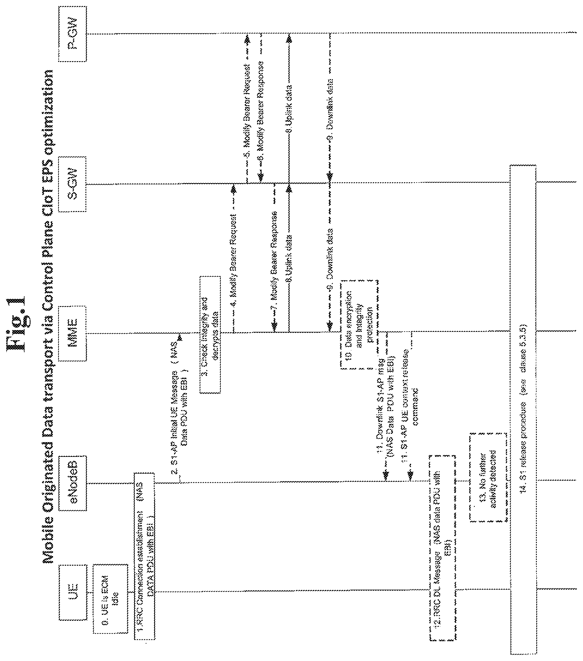
A UE that supports NB-IoT shall always indicate support for Control Plane CIoT EPS Optimization (i.e Control Plane CIoT EPS Optimization support is mandatory). If a UE includes a Preferred Network Behavior, the Preferred Network Behavior defines the Network Behavior the UE is expecting to be available in the network. When selecting an MME for a UE that is using the NB-IoT Radio Access Technology (RAT), and/or for a UE that signals support for CIoT EPS Optimization in RRC signalling, the eNodeB's MME selection algorithm shall select an MME taking into account the MME's support (or non-support) for the Release 13 NAS signalling protocol. Data Transfer in Control Plane CIoT EPS Optimization If the UE and the MME use the Control Plane CIoT EPS Optimization, they can transfer data in NAS PDUs including the EPS Bearer Identity of the PDN connection they relate to. Both the IP and Non IP data types are supported. This is accomplished by using the NAS transport capabilities of RRC and S1 application protocol (S1-AP) protocols and the data transport of GPRS Tunneling Protocol for User Plane (GTP-u) tunnels between a MME and a Serving Gateway (S-GW) and between a S-GW and a PDN Gateway (P-GW), or if a Non-IP connection is provided by via the MME with the Service Capability Exposure Function (SCEF), then data transfer occurs as indicated in TS 23.682. To minimize potential conflicts between NAS signaling PDUs and NAS Data PDUs, the MME should complete any security related procedures (e.g. Authentication, Security Mode Command, Globally Unique Temporary UE Identity (GUTI) reallocation) before alerting the home subscriber server (HSS), mobile switching center (MSC) or S-GW 11 of the UE's entry into EPS connection management (ECM)-CONNECTED state, and before commencing downlink transfer of NAS Data PDUs. The data transmission via Control Plane CIoT EPS Optimization in 3GPP Rel-13 is expected to add an extra load to the network control plane entities like MME and SGSN which are used to handle signalling messages that are relatively smaller compared to the data that MME and SGSN should handle with the deployment of the Control Plane CIoT EPS Optimization. That is why in Rel-14 the 3GPP has continued to study further architecture enhancement to support Cellular Internet of Things (CIoT). One of the Key issues identified in the 3GPP Rel-14 study (Technical Report TR 23.730) is the core network (CN) overload protection for UE supporting control plane EPS CIoT Optimization which requires from the system to support procedures to handle the CN overload from data transmission via Control Plane CIoT EPS Optimization. Problem Statement: The Control Plane CIoT data transfer can contribute greatly for the MME/SGSN overload if an appropriate load control with emphasis on communication via Control Plane CIoT is not put in place. The solution proposals are looking at how to further improve the system (e.g the MME/SGSN or the SCEF or the S-GW/P-GW) overload control from excessive use of Control Plane CIoT EPS Optimization for data transfer. In an exemplary aspect of the disclosure, there is provided a User Equipment (UE), comprising: a receiver configured to receive a control plane data back-off timer included in a Service Accept message from a network; and a controller configured to consider a current data transfer via a control plane as successful based on the Service Accept message and not to initiate data transfer via Control Plane Cellular Internet of Things (CIoT) Evolved Packet System (EPS) Optimization while the control plane data back-off timer is running. In another exemplary aspect of the disclosure, there is provided a communication method of a User Equipment (UE), comprising: receiving a control plane data back-off timer included in a Service Accept message from a network; and considering a current data transfer via a control plane as successful based on the Service Accept message and not to initiate data transfer via Control Plane Cellular Internet of Things (CIoT) Evolved Packet System (EPS) Optimization while the control plane data back-off timer is running. In another exemplary aspect of the disclosure, there is provided a non-transitory computer readable medium storing instructions operable to program a programmable processor for a User Equipment (UE) to perform a method comprising: receiving a control plane data back-off timer included in a Service Accept message from a network; and considering a current data transfer via a control plane as successful based on the Service Accept message and not to initiate data transfer via Control Plane Cellular Internet of Things (CIoT) Evolved Packet System (EPS) Optimization while the control plane data back-off timer is running. In another exemplary aspect of the disclosure, there is provided a communication system, comprising a User Equipment (UE) and a core network node, wherein the core network node is configured to transmit a control plane data back-off timer included in a Service Accept message to the UE, the UE is configured to: receive the control plane data back-off timer included in the Service Accept message, and consider a current data transfer via a control plane as successful based on the Service Accept message and not to initiate data transfer via Control Plane Cellular Internet of Things (CIoT) Evolved Packet System (EPS) Optimization while the control plane data back-off timer is running. In another exemplary aspect of the disclosure, there is provided a communication method of a communication system including a User Equipment (UE) and a core network node, the communication method comprising: transmitting a control plane data back-off timer included in a Service Accept message from the core network node to the UE; and considering a current data transfer via a control plane as successful based on the Service Accept message and not initiating data transfer via Control Plane Cellular Internet of Things (CIoT) Evolved Packet System (EPS) Optimization while the control plane data back-off timer is running. Aspects of the disclosure extend to corresponding systems, methods, and computer program products such as computer readable storage media having instructions stored thereon which are operable to program a programmable processor to carry out a method as described in the aspects and possibilities set out above or recited in the claims and/or to program a suitably adapted computer to provide the apparatus recited in any of the claims. Each feature disclosed in this specification (which term includes the claims) and/or shown in the drawings may be incorporated in the invention independently (or in combination with) any other disclosed and/or illustrated features. In particular but without limitation the features of any of the claims dependent from a particular independent claim may be introduced into that independent claim in any combination or individually. Each solution is described in a more specific embodiment as an example how to apply the invention to a 3GPP network. Even if the described solution is foreseen to be used in a 3GPP mobile network, using global system for mobile communications (GSM), GPRS, universal mobile telecommunications system (UMTS), high speed packet access (HSPA), LTE, LTE-Advanced (LTE-A) or New Radio access, but it is not limited to such a network and could be used in the same way for any other cellular or mobile network, e.g. CDMA2000, Bluetooth, IEEE 802.11 variants, ZigBee etc., i.e. any access technologies and core network technologies. The described protocol options are considered to be NAS, S1 application protocol (S1-AP), DIAMETER, GPRS Tunneling Protocol (GTP), mobile application part (MAP), session initiation protocol (SIP), but could be any other as well like hypertext transfer protocol (HTTP), Extensible Markup Language (XML) configuration access protocol (XCAP), remote authentication dial in user service (RADIUS), next generation non-access stratum (NG NAS), etc. The disclosure can be further mapped to the functional entities of the NextGen study for future 3GPP mobile networks in the following way:
Solution 1—New EMM/ESM Cause for Congestion from Control Plane Data One possible solution to address the system (e.g. MME/SGSN) overload from excessive use of Control Plane CIoT EPS Optimization for data transfer, both for IP and non-IP data, is to introduce a new NAS level EPS Mobility Management (EMM)/ESM cause—Congestion from Control Plane data (or any other name that indicates a congestion from data transfer via Control Plane). The role of this new congestion cause is for the MME/SGSN to indicate to the UE a congestion from Control Plane data. This new congestion cause could be returned to the UE within the existing EMM cause/IE or ESM cause/IE or as a new cause/IE. Below some use cases are described where this newly proposed Congestion from Control Plane data cause could be used. Solution 1, Scenario A)—Congestion from Control Plane Data Cause Returned During Attach/TAU/RAU Procedures. One possible scenario where the proposed new Congestion from Control Plane data cause can be used is during the Attach/TAU/RAU procedures (for example, as illustrated in 1) At certain point, the MME/SGSN 9 or the network 7 in general may become overloaded or close to overload with control plane data or overloaded in general (e.g. the load reaches an operator defined threshold or the criteria for overload is simply based on an operator policy). A criterion for overload can also be an overload from control plane data indication received either from the connected SCEF 10 or from the S-GW 11/P-GW 12 (e.g. an Overload Start message or a Control Plane Overload Start message or any other name for the purpose of overload indication from the SCEF 10 or S-GW 11/P-GW 12 as shown in the 2) The UE 3 initiates a registration or re-registration procedure by triggering the Attach/TAU/RAU Request message. In the Attach/TAU/RAU Request message, the UE 3 includes a Preferred Network Behavior parameter where the UE 3 indicates its support for Control Plane CIoT EPS Optimization and/or for User Plane CIoT EPS Optimization. The UE 3 also indicates it's preferred CIoT EPS Optimization (i.e. Control Plane CIoT EPS or User Plane CIoT EPS Optimization). 3) If the UE 3 indicated support and preference for Control Plane CIoT EPS Optimization and the MME/SGSN 9 and/or the network 7 is overloaded or close to overload (e.g. the MME/SGSN 9 has entered protection from control plane data overload mode), the MME/SGSN 9 may decide to respond with one of the following:
The UE 3 that receives a Congestion from Control Plane data cause/IE (or any other new cause/IE designated for the purpose of indication for overload from Control Plane CIoT EPS Optimization) within the Attach/TAU/RAU Accept messages, the UE 3 shall start the included Control Plane data back-off timer and shall not send any NAS messages to the MME/SGSN 9 if a NAS data PDU with user data is included (e.g. a Control Plane Service Request message for data transfer via Control Plane CIoT EPS Optimization) for the duration of the Control Plane data back-off timer. If the UE 3 receives a paging request from the MME/SGSN 9 while the Control Plane CIoT data back-off timer is running, the UE 3 shall answer the paging regardless of whether the Control Plane data back-off timer is running or not. Solution 1, Scenario B)—Congestion from Control Plane Data Cause Returned Via Service Accept. Another scenario where the proposed new Congestion from Control Plane data cause/IE can be used is during the Control Plane Service procedure where the Congestion from Control Plane data cause can be returned with the Service Accept message. This scenario is illustrated in 1) At certain point, the MME/SGSN 9 or the network 7 in general may become overloaded or close to overload with control plane data or overloaded in general (e.g. the load reaches an operator defined threshold or the criteria for overload is simply based on an operator policy). A criterion for overload can also be an overload from control plane data indication received either from the connected SCEF 10 or from the S-GW 11/P-GW 12 (e.g. an Overload Start message or a Control Plane Overload Start message or any other message or indication for the purpose of overload indication from the SCEF 10 or S-GW 11/P-GW 12 as shown in the 2) When an application in the UE 3 or the UE 3 itself requests a data transfer via control plane, the UE 3 initiates the Control Plane Service Request procedure by triggering the Control Plane Service Request message, see 3GPP TS 24.301. The UE 3 includes the data to be transferred in the Control Plane Service Request message (e.g. data PDU or NAS PDU) destined to the MME/SGSN 9. 3) The MME/SGSN 9 accepts the request for the data transfer via control plane and answers the UE 3 with a Service Accept message. Then the MME/SGSN 9 completes the transfer of the control plane data as per TS23.401. If the MME/SGSN 9 and/or the network 7 is overloaded or close to overload (e.g. the MME/SGSN has entered protection from control plane data overload mode), the MME/SGSN 9 may return within the Service Accept message a cause or IE (e.g. a Congestion from Control Plane data cause/IE). The MME/SGSN 9 may also include a Control Plane data back-off timer in order to restrict the UE 3 from coming back for data transfer via Control Plane CIoT EPS Optimization for the duration of this Control Plane data back-off timer. When deciding the duration for the Control Plane data back-off timer the MME/SGSN 9 may take into account the overload duration indicated from the SCEF 10/S-GW 11, if any. This new Congestion from Control Plane data cause or IE can be returned within the existing EMM cause/IE or ESM cause/IE or as a new cause/IE. When the MME/SGSN 9 indicated a Congestion from Control Plane data cause in a Service Accept message and included a Control Plane data back-off timer, the MME/SGSN 9 may store the Control Plane data back-off time per UE 3. The MME/SGSN 9 may immediately reject any subsequent new request for the data transfer via Control Plane CIoT EPS Optimization (e.g. the Control Plane Service Request or any other NAS message for the purpose of data transfer via control plane data) from the UE 3 before the stored Control Plane data back-off timer expires. The UE 3 that receives a Congestion from Control Plane data cause/IE (or any other new cause/IE designated for the purpose of indication for overload from Control Plane CIoT EPS Optimization) within the Service Accept message and a Control Plane data back-off timer is included, the UE 3 shall finalise the already ongoing data transfer via control plane data and as soon as the UE 3 finishes the data transfer and falls back to the Idle Mode, the UE 3 shall start the included Control Plane data back-off timer and shall not send any NAS messages to the MME/SGSN 9 if a NAS data PDU with user data is included (e.g. a Control Plane Service Request message or any other message for the purpose for data transfer via Control Plane CIoT EPS Optimization) for the duration of the Control Plane data back-off timer. If the UE 3 receives a paging request from the MME/SGSN 9 while the Control Plane CIoT data back-off timer is running, the UE 3 shall answer the paging regardless of whether the Control Plane data back-off timer is running or not. Solution 1, Scenario C)—Congestion from Control Plane Data Cause Returned Via Service Reject or Control Plane Service Reject. Another scenario where the proposed new Congestion from Control Plane data cause/IE can be used is during the Control Plane Service procedure where the Congestion from Control Plane data cause can be returned with the existing Service Reject message or in a new Control Plane Service Reject message. This scenario is illustrated in 1) At certain point, the MME/SGSN 9 or the network 7 in general may become overloaded or close to overload with control plane data or overloaded in general (e.g. the load reaches an operator defined threshold or the criteria for overload is simply based on an operator policy). A criteria for overload can also be an overload from control plane data indication received either from the connected SCEF 10 or from the S-GW 11/P-GW 12 (e.g. an Overload Start message or a Control Plane Overload Start message or any other message or indication for the purpose of overload indication from the SCEF 10 or S-GW 11/P-GW 12 as shown in the 2) When an application in the UE 3 or the UE 3 itself requests a data transfer via control plane, the UE 3 initiates the Control Plane Service Request procedure by triggering the Control Plane Service Request message. The UE 3 includes the user data to be transferred in the Control Plane Service Request message (e.g. data PDU or NAS PDU) destined to the MME/SGSN 9. 3) If the MME/SGSN 9 and/or the network 7 is overloaded or close to overload (e.g. the MME/SGSN 9 has entered protection from control plane data overload mode), the MME/SGSN 9 may reject the request for the data transfer via control plane by the UE 3 by returning a Service Reject message or a new message called Control Plane Service Reject message, for example or any other name for the purpose of rejecting a request for data transfer via control plane). The MME/SGSN 9 may also return within the reject message a new cause (e.g. a Congestion from Control Plane data or any other name that indicates a congestion from data transfer via control plane). This new Congestion from Control Plane data cause or IE can be returned within the existing EMM cause/IE or ESM cause/IE or as a new cause/IE. The MME/SGSN 9 may also include a Control Plane data back-off timer in order to restrict the UE 3 from coming back for data transfer via Control Plane CIoT EPS Optimization for the duration of this Control Plane data back-off timer. When deciding the duration for the Control Plane data back-off timer the MME/SGSN 9 may take into account the overload duration indicated from the SCEF 10/S-GW 11, if any. When the MME/SGSN 9 indicated a Congestion from Control Plane data cause and included a Control Plane data back-off timer, MME/SGSN 9 may store the Congestion from Control Plane data cause and the Control Plane data back-off timer per UE 3. The MME/SGSN 9 may reject any subsequent request for data transfer via Control Plane CIoT EPS Optimization (i.e. Control Plane Service Request or any other NAS message for the purpose of data transfer via Control Plane CIoT Optimization) from the UE 3 before the stored Control Plane data back-off timer expires. The UE 3 that receives a Congestion from Control Plane data cause/IE (or any other new cause/IE designated for the purpose of indication for overload from Control Plane CIoT EPS Optimization) within the Service Reject message or with a new Control Plane Service Reject message or any other name with the purpose of rejection a request for data transfer via control plane shall drop the ongoing data transfer via control plane. If a Control Plane data back-off timer is included, the UE 3 shall start the Control Plane data back-off timer and shall not send any NAS messages to the MME/SGSN 9 if a NAS data PDU with user data is included (e.g. a Control Plane Service Request message or any other message for the purpose for data transfer via Control Plane CIoT EPS Optimization) for the duration of the Control Plane data back-off timer. Common UE Behavior while the Control Plane Back-Off Timer is Running If a UE 3 receives a Congestion from Control Plane data cause and a Control plane data back-off timer or only the Control Plane back-off timer via one of the above listed scenarios in Solution 1 and the UE 3 has started the Control Plane back-off timer:
Solution 2—New Congestion from Control Plane Data Per Bearer Another possibility to control the congestion from control plane data is to apply congestion control for a particular bearer Solution 2, Scenario A)—ESM Congestion from Control Plane Data Cause Towards SCEF. One possible solution to control the overload from Control Plane data (CIoT or any other type of data) for non-IP data via SCEF 10 is to introduce an ESM cause for congestion control per bearer or per SCEF 10, for example, as illustrated in 1) When an SCEF 10 gets congested, the SCEF 10 indicates a Start Congestion Control message to MME/SGSN 9. The SCEF 10 may include in this message a congestion from control plane data cause, a weight factor and a time duration. 2) When the MME/SGSN 9 receives the Start Congestion Control message from the SCEF 10 with the congestion from control plane cause indication, the MME/SGSN 9 activates congestion control for CIoT data towards the UE 3 3) At some point, the UE 3 may initiate a request for control Plane data transfer on a specific bearer by sending a Control Plane Service Request message towards the MME/SGSN 9. The UE 3 may include the bearer identity (e.g. EPS Bearer ID (EBI)) along with the data for transfer in the ESM container. 4) The MME/SGSN 9 starts applying the congestion control towards the UE 3 for the bearer identity received by the UE 3 and derives a back-off timer based on the time duration from the SCEF 10 5) The MME/SGSN 9 then returns a Service Reject message towards the UE 3 and includes an EMM failure cause (Congestion Control (CC) for CIoT) together with the EBI# and a back-off timer derived from the duration parameter received by the SCEF 10. Alternatively, the MME/SGSN 9 sends a Service Reject message towards the UE 3 which includes a NAS ESM message encapsulated in the Service Request message and this NAS ESM message contains a new ESM cause (CC for CIoT) and the back-off timer derived from the duration parameter received by the SCEF 10. 6) When the UE 3 receives the Service Reject message with the new EMM or ESM cause (CC for CIoT) according to step S), the UE 3 starts applying congestion control for data over EBI#X. NAS ESM signaling for EBI#X is allowed. Solution 2, Scenario B)—ESM Congestion from Control Plane Data Cause Towards SGi. Another possible solution to control the overload from Control Plane data (CIoT or any other type of data) for IP and non-IP data via SGi is to introduce an ESM cause for congestion control per bearer or PDN connection towards the SGi. This is illustrated in 1) When the P-GW 12 gets congested from control plane data, the P-GW 12 triggers the Start Congestion Control procedure by indication for control plane congestion to the S-GW 11. The P-GW 12 may include in this message a congestion from control plane data cause, a weight factor and a time duration. The S-GW 11 further indicates a congestion from control plane data towards the MME/SGSN 9. 2) When the MME/SGSN 9 receives an indication from control plane data (e.g. a Start Congestion Control message or any other message for the same purpose) from the S-GW 11, the MME/SGSN 9 activates congestion control for CIoT data towards UEs 3 having PDN connections towards the SCEF 10. 3) At some point, the UE 3 may initiate a request for control plane data transfer towards SGi on specific bearer by sending a Control Plane Service Request message towards the MME/SGSN 9. The UE 3 may include the bearer identity (e.g. EBI) along with the data for transfer in the ESM container. 4) The MME/SGSN 9 starts applying the congestion control towards the UE 3 for the bearer identity received by the UE 3 and derives a back-off timer based on the time duration from the P-GW 12. 5) The MME/SGSN 9 then returns a Service Reject message towards the UE 3 and includes a new ESM cause (CC for CIoT) and the back-off timer derived from the duration parameter received by the P-GW 12. 6) When the UE 3 receives the Service Reject message with the new ESM cause (CC for CIoT), the UE 3 starts applying congestion control for data over EBI#X. NAS ESM signalling for EBI#X is allowed. Beneficially, the above described exemplary embodiments include, although they are not limited to, one or more of the following functionalities. Solution 1:
Solution 2:
It can be seen that the above embodiments describe the features of:
It can be seen that the above embodiments beneficially provide a number of benefits, including (but not limited to) network overload protection from control plane data. System Overview As is well known, a mobile device 3 may enter and leave the areas (i.e. radio cells) served by the base stations 5 as the mobile device 3 is moving around in the geographical area covered by the telecommunication system 1. In order to keep track of the mobile device 3 and to facilitate movement between the different base stations 5, the core network 7 comprises at least one mobility management entity (MME) 9. In some core networks, an SGSN may be used instead of the MME. The MME/SGSN 9 is in communication with the base station 5 coupled to the core network 7. The core network 7 also includes an SCEF 10, and one or more gateways, such as a serving gateway (S-GW) 11 and/or a packet data network gateway (P-GW) 12. Although shown separately, it will be appreciated that the functionalities of the S-GW 11 and the P-GW 12 may be provided by a single network entity, if appropriate. The mobile devices 3 and their respective serving base stations 5 are connected via an LTE air interface, the so-called “Uu” interface. Neighbouring base stations 5 are connected to each other via a so-called “X2” interface (not shown in User Equipment (UE) MME/SGSN SCEF/S-GW Modifications and Alternatives Detailed embodiments have been described above. As those skilled in the art will appreciate, a number of modifications and alternatives can be made to the above embodiments whilst still benefiting from the inventions embodied therein. By way of illustration only a number of these alternatives and modifications will now be described. In the above description, the UE 3, the MME/SGSN 9, and the SCEF 10/S-GW 11 are described for ease of understanding as having a number of discrete modules (such as the communication control modules). Whilst these modules may be provided in this way for certain applications, for example where an existing system has been modified to implement the invention, in other applications, for example in systems designed with the inventive features in mind from the outset, these modules may be built into the overall operating system or code and so these modules may not be discernible as discrete entities. These modules may also be implemented in software, hardware, firmware or a mix of these. Each controller may comprise any suitable form of processing circuitry including (but not limited to), for example: one or more hardware implemented computer processors; microprocessors; central processing units (CPUs); arithmetic logic units (ALUs); input/output (JO) circuits; internal memories/caches (program and/or data); processing registers; communication buses (e.g. control, data and/or address buses); direct memory access (DMA) functions; hardware or software implemented counters, pointers and/or timers; and/or the like. In the above embodiments, a number of software modules were described. As those skilled in the art will appreciate, the software modules may be provided in compiled or un-compiled form and may be supplied to the UE 3, the MME/SGSN 9, and the SCEF 10/S-GW 11 as a signal over a computer network, or on a recording medium. Further, the functionality performed by part or all of this software may be performed using one or more dedicated hardware circuits. However, the use of software modules is preferred as it facilitates the updating of the UE 3, the MME/SGSN 9, and the SCEF 10/S-GW 11 in order to update their functionalities. In the above embodiments, a 3GPP radio communications (radio access) technology is used. However, any other radio communications technology (e.g. WLAN, Wi-Fi, WiMAX, Bluetooth, etc.) may also be used in accordance with the above embodiments. The above embodiments are also applicable to ‘non-mobile’ or generally stationary user equipment. Examples of IoT Applications Some examples of Internet of Things (or MTC) applications are listed in the following table (source: 3GPP TS 22.368 V 13.1.0, Annex B). This list is not exhaustive and is intended to be indicative of the scope of Internet of Things/machine-type communication applications. Various other modifications will be apparent to those skilled in the art and will not be described in further detail here. Abbreviations and Terminology The following abbreviations and terminology (whenever differently stated) are used in the current document: In addition, the following terminologies are used within this document: Cellular IoT: Cellular network supporting low complexity and low throughput devices for a network of Things. Cellular IoT supports both IP and Non-IP traffic. Narrowband-IoT (NB-IoT): a 3GPP Radio Access Technology that forms part of Cellular IoT. The Narrowband-IoT allows access to network services via E-UTRA with a channel bandwidth limited to 180 kHz (corresponding to one Physical Resource Block (PRB)). Unless otherwise indicated in a clause or sub-clause, Narrowband-IoT is a subset of the Evolved Universal Terrestrial Radio Access Network (E-UTRAN). WB-E-UTRAN: Wide Band (WB)-E-UTRAN is the part of the E-UTRAN that excludes the NB-IoT Control Plane CIoT EPS Optimization—support of infrequent small data transmission (for IP data, non-IP data and SMS) via optimized Control Plane signalling. Mandatory for UE 3 and the network. User Plane CIoT EPS Optimization—support of infrequent small data transmission (for IP data and SMS) via optimized User Plane. Optional for both the UE 3 and the network. This application is based upon and claims the benefit of priority from European patent application No. 16193159.7 filed on Oct. 10, 2016, the disclosure of which is incorporated herein in its entirety by reference. This disclosure provides a User Equipment (UE) (3), including a receiver (31) and a controller (34). The receiver (31) is configured to receive a control plane data back-off timer included in a Service Accept message from a network. The controller (34) is configured to consider a current data transfer via a control plane as successful based on the Service Accept message and not to initiate data transfer via Control Plane Cellular Internet of Things (CIoT) Evolved Packet System (EPS) Optimization while the control plane data back-off timer is running. 1-30. (canceled) 31. A UE (User Equipment), comprising:
a memory storing instructions; and at least one processor configured to process the instructions to:
receive a control plane data back-off timer included in a Service Accept message from a network, and consider a current data transfer via a control plane as successful based on the Service Accept message and not to initiate data transfer via Control Plane CIoT (Cellular Internet of Things) EPS (Evolved Packet System) Optimization while the control plane data back-off timer is running. 32. The UE according to receive the control plane data back-off timer included in a Service Reject message from the network, and consider the current data transfer via the control plane as unsuccessful based on the Service Reject message including a congestion cause and not to initiate data transfer via the Control Plane CIoT EPS Optimization while the control plane data back-off timer is running. 33. The UE according to 34. The UE according to 35. The UE according to 36. The UE according to 37. A communication method of a UE (User Equipment), comprising:
receiving a control plane data back-off timer included in a Service Accept message from a network; and considering a current data transfer via a control plane as successful based on the Service Accept message and not to initiate data transfer via Control Plane CIoT (Cellular Internet of Things) EPS (Evolved Packet System) Optimization while the control plane data back-off timer is running. 38. The communication method according to receiving the control plane data back-off timer included in a Service Accept message from the network; and considering the current data transfer via the control plane as unsuccessful based on the Service Reject message including a congestion cause and not to initiate data transfer via the Control Plane CIoT EPS Optimization while the control plane data back-off timer is running. 39. The communication method according to initiating user data transmission via the Control Plane CIoT EPS Optimization for at least one of high priority access, emergency services and mobile terminated services while the control plane data back-off timer is running. 40. The communication method according to stopping the control plane data back-off timer at PLMN change. 41. The communication method according to stopping the control plane data back-off timer after successful Tracking Area Update procedure. 42. The communication method according to continuing running the control plane data back-off timer when the UE moves to another cell. 43. A communication system, comprising:
a User Equipment (UE); and a core network node, wherein the core network node is configured to transmit a control plane data back-off timer included in a Service Accept message to the UE, the UE is configured to:
receive the control plane data back-off timer included in the Service Accept message, and consider a current data transfer via a control plane as successful based on the Service Accept message and not to initiate data transfer via Control Plane CIoT (Cellular Internet of Things) EPS (Evolved Packet System) Optimization while the control plane data back-off timer is running.TECHNICAL FIELD
BACKGROUND ART
SUMMARY OF INVENTION
Technical Problem
Solution of Problem
BRIEF DESCRIPTION OF DRAWINGS
DESCRIPTION OF EMBODIMENTS
SUMMARY
Security Surveillance systems Backup for landline Control of physical access (e.g. to buildings) Car/driver security Tracking & Tracing Fleet Management Order Management Pay as you drive Asset Tracking Navigation Traffic information Road tolling Road traffic optimisation/steering Payment Point of sales Vending machines Gaming machines Health Monitoring vital signs Supporting the aged or handicapped Web Access Telemedicine points Remote diagnostics Remote Sensors Maintenance/Control Lighting Pumps Valves Elevator control Vending machine control Vehicle diagnostics Metering Power Gas Water Heating Grid control Industrial metering Consumer Devices Digital photo frame Digital camera eBook 3GPP 3rdGeneration Partnership Project APN Access Point Name AS Access Stratum CIoT Cellular Internet of Things EMM EPS Mobility Management EPS Evolved Packet System ESM EPS Session management E-UTRAN Evolved Universal Terrestrial Radio Access Network (also used as EUTRAN) GPRS General Packet Radio Service GTP GPRS Tunneling Protocol GUTI Globally Unique Temporary ID HPLMN Home Public Land Mobile Network HSS Home Subscriber Server IE Information Element MME Mobility Management Entity MNO Mobile Network Operator NAS Non Access Stratum NB, eNB Node B, evolved Node B (but can also be any ‘RAN node’ implementing 2G, 3G, 4G, or future 5G technology) NIDD Non-IP Data Delivery PGW Packet Data Network Gateway PDN Packet Data Networks PDU Protocol Data Unit RAU Routing Area Update RNC Radio Network Controller RRC Radio Resource Control PLMN Public Land Mobile Network S1-U Reference point between E-UTRAN and Serving GW S1AP S1 Application Protocol SCEF Service Capability Exposure Function SGSN Serving GPRS Support Node S-GW Serving Gateway SMS Short Message Service TAU Tracking Area Update UE User Equipment UTRAN UMTS Terrestrial Radio Access Network