VALVE MECHANISM AND SHOCK ABSORBER
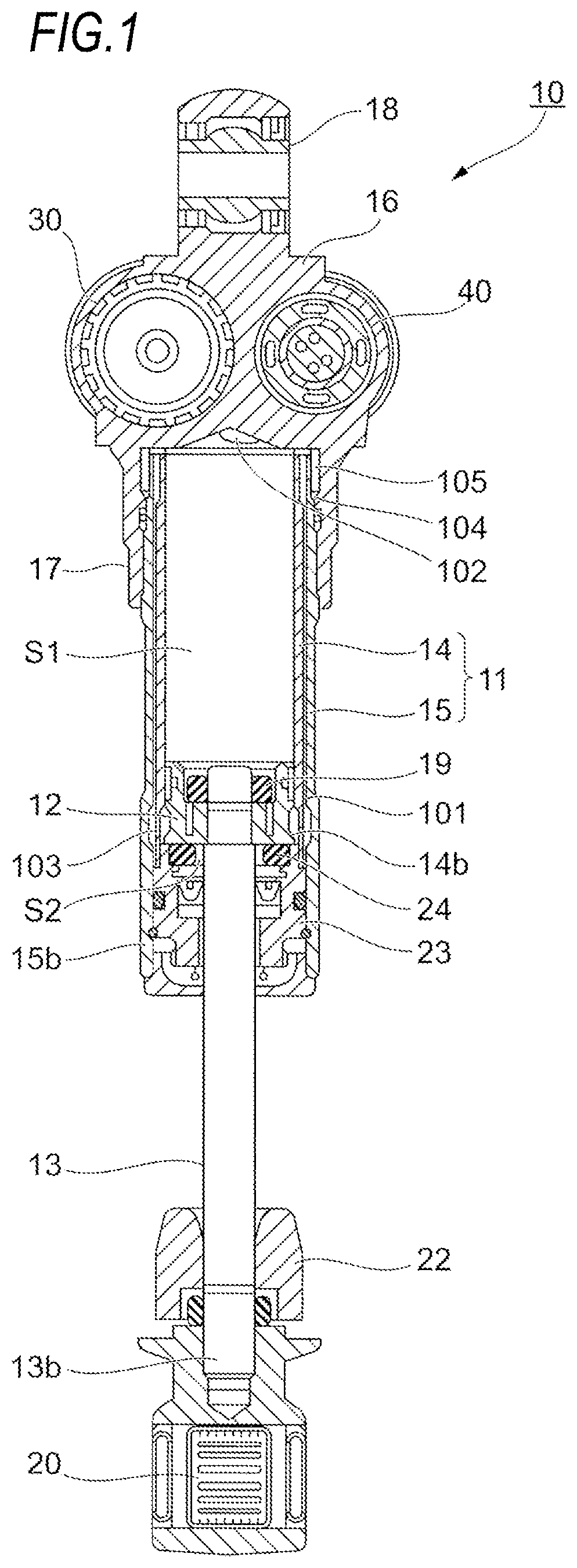
This application is a continuation of PCT application No. PCT/JP2018/023509, which was filed on Jun. 20, 2018, the content of which is incorporated herein by reference in its entirety. The present invention relates to a valve mechanism and a shock absorber. Suspension systems for vehicles such as automobiles are equipped with a shock absorber which uses a damping force generation mechanism to appropriately reduce vibration transmitted from the road surface to vehicle body during traveling and improve ride comfort and steering stability. The shock absorber has a flow path through which fluid flows. In some cases, a valve body, which forms a part of the flow path, is elastically deformed by being pressed by a drive unit, thereby controlling a flow path area to adjust a damping force. For example, Patent Literature 1 discloses a control valve portion which includes a valve seat member having a valve seat formed radially outside an opening at one end of a central flow path for oil, a drive valve provided so as to be movable in a direction of approaching or separating with respect to the valve seat, a plurality of valve bodies provided between the valve seat and the drive valve and having opening portions through which oil flows, a solenoid actuator which changes a gap flow path between an inner peripheral portion of the valve body and the valve seat by moving the drive valve in a direction to approach the valve seat and elastically deforming a valve body of the plurality of valve bodies, which is the valve body closest to the drive valve, in a direction in which an inner peripheral portion thereof approaches the valve seat with respect to an outer peripheral portion of the valve body, and a valve rotation restricting portion which restricts relative rotation of the plurality of valve bodies in a circumferential direction in a state where the openings of the plurality of valve bodies communicate with each other.
When the valve body is pressed and elastically deformed by the drive unit to control the flow path area, the pressure tends to change due to the jet of the fluid, so that a desired damping force may not be obtained. An object of the invention is to provide a valve mechanism or the like which can easily obtain a desired damping force. In a control valve portion of the related art as disclosed in Patent Literature 1, by providing a difference in a pressure receiving area for receiving the fluid pressure between one end side and the other end side, a thrust for moving the drive valve downward is generated. In order to control the damping force with high accuracy, it is important to control the thrust of the drive valve with high accuracy. Therefore, in controlling the damping force, it is important to control the difference between the pressure receiving areas described above. The present inventors have investigated the characteristics of a shock absorber having the control valve portion of the related art. As a result, it is found that, in the shock absorber of the related art, (1) when the fluid flows at a high flow rate from a lower side to an upper side of the drive valve during the extension stroke in which the overall length of the shock absorber extends, the fluid enters between the valve bodies, and therefore the pressure receiving area may fluctuate from the designed value. Therefore, countermeasures to solve this are examined. As a result, the inventor has found that, by providing a step portion extending radially outward of a shaft portion of the drive valve, it is possible to prevent the flow of the fluid which tries to enter between the valve bodies. The invention has been completed based on such findings. Hereinafter, the invention will be described. Under such a purpose, an aspect of the invention completed is a valve mechanism which includes a cylindrical body having a hollow portion penetrating in an axial direction, a plurality of valve bodies including a first valve body having a through-hole penetrating in the axial direction and being arranged to be in contact with an axial end surface of the cylindrical body, and a drive valve arranged movably in the axial direction and disposed on a side opposite to the cylindrical body with respect to the plurality of valve bodies, where the drive valve includes a shaft portion having therein a flow path penetrating in the axial direction and a step portion extending from an outer peripheral surface of the shaft portion to a radial outside of the shaft portion and the shaft portion has a tip portion which extends further on the cylindrical body side than the step portion, and further an outer diameter of the tip portion is smaller than an outer diameter of the step portion, and still further a gap between the plurality of valve bodies is changed by elastically deforming an inner peripheral portion of the valve body, which comes into contact with the drive valve which is moved in a direction approaching the valve body, in a direction approaching the cylindrical body with respect to an outer peripheral portion of the valve body. Here, the step portion may be in contact with a second valve body which is included in the plurality of valve bodies and disposed closest to the drive valve side and the tip portion may be in contact with the valve body which is arranged further on the cylindrical body side than the second valve body. This makes it easier to control the flow path area. A spacer may be provided between the first valve body and the second valve body. As a result, a radial flow path can be formed in the valve body. Further, the tip portion may have an annular recess portion on an end surface on the cylindrical body side. Thereby, the contact area between the tip portion and the valve body can be reduced. The step portion may have an annular shape. This makes it easier to form the step portion. The hollow portion may have an orifice portion of which inner diameter increases as it approaches the valve body. This makes it difficult for the cylindrical body to obstruct the flow of the fluid. The cylindrical body may have an upper end portion which is in contact with the valve body. Thereby, in an extension stroke, a change in the pressure receiving area due to the ejection of the fluid can be suppressed. The valve body may have an annular outer frame portion, an annular inner frame portion arranged radially inward of the outer frame portion, and a plurality of spoke portions connecting the outer frame portion and the inner frame portion and the plurality of spoke portions may be spaced apart from each other. Thereby, a plurality of axial flow paths can be formed in the valve body. The plurality of valve bodies may be three or more valve bodies. This makes it easier to control the flow path area. The invention is a shock absorber which includes the valve mechanism described above, a cylinder which accommodates fluid, a piston which is slidably fitted in the cylinder, a piston rod which is connected to the piston and extends out of the cylinder, and an oil reservoir for compensating for an oil amount corresponding to an entering volume of the piston rod when the piston rod enters the cylinder, where the fluid flowing due to the sliding of the piston moves into the valve mechanism to generate a damping force and the fluid having passed through the valve mechanism can flow through the oil reservoir. In the shock absorber described above, a damping force generating mechanism which is provided independently of the valve mechanism and generates a damping force due to the flow of the fluid may be further provided and the fluid which has passed through the damping force generating mechanism can flow through the oil reservoir. Thus, the damping force can be adjusted by the valve mechanism. According to an aspect of the invention, it is possible to provide a valve mechanism or the like which can easily obtain a desired damping force. Hereinafter, embodiments for implementing a valve mechanism, a damping force generator, and a shock absorber according to the invention will be described with reference to the accompanying drawings. However, the invention is not limited to only those embodiments. Description of Overall Configuration of Shock Absorber 10 As illustrated in The shock absorber 10 includes a cylinder 11, a piston 12, a piston rod 13, a reservoir 30, a damping force generator 40, and a spring (not illustrated). The cylinder 11 accommodates oil, which is an example of a fluid. The cylinder 11 is formed by an inner cylinder 14 and an outer cylinder 15 which form a concentric double pipe. On an upper end side of the shock absorber 10, a damper case 16 provided with the vehicle-body-side mounting portion 18 is arranged. The damper case 16 is provided with a cylindrical cylinder holding portion 17 extending toward the cylinder 11. The upper ends of the outer cylinder 15 and the inner cylinder 14 are inserted into and held by the cylinder holding portion 17. The inner diameter of the outer cylinder 15 of the cylinder 11 is formed to be larger by a certain dimension than the outer diameter of the inner cylinder 14. As a result, a cylindrical flow path 101 is formed between the outer cylinder 15 and the inner cylinder 14. The outer cylinder 15 is formed so as to protrude below a lower end portion 14 A rebound rubber 24 is provided on the upper side of the rod guide 23 to absorb the impact when the piston 12 collides. The piston 12 is fixed to an end of the piston rod 13. Further, the piston 12 is provided in contact with the cylinder 11 so as to be movable in an axial direction (up-down direction in An oil hole 102 is formed in the damper case 16 at a position facing an upper end opening of the inner cylinder 14 and opens into the piston side oil chamber S1. The oil hole 102 communicates with a first oil chamber S11 (see A plurality of oil holes 103 are formed in the lower end portion 14 Further, at the upper end of the flow path 101, a plurality of oil holes 104 are formed in the outer cylinder 15 at a portion facing the cylinder holding portion 17. Those oil holes 104 allow the piston-side oil chamber S1 to communicate with the flow path 101. In the damper case 16, a flow path 105 communicating with a third oil chamber S13 (see The piston rod 13 moves relatively in the axial direction of the cylinder 11. The piston rod 13 is fixed to the piston 12 by a nut 19. The piston rod 13 extends along the center axis direction of the inner cylinder 14, penetrates the rod guide 23, and protrudes outside the cylinder 11. Therefore, it can be said that the piston rod 13 is a member connected to the piston 12 and extended to the outside of the cylinder 11. The axle-side mounting member 20 is provided at a lower end 13 Description of Reservoir 30 As illustrated in Oil is filled in the piston-side oil chamber S1 in the cylinder 11 as described above, the rod-side oil chamber S2, the flow path 101 between the inner cylinder 14 and the outer cylinder 15, the oil reservoir S3 in the reservoir 30, and the damping force generator 40 described below. Description of Damping Force Generator 40 The damping force generator 40 has a flow path through which oil flows with the relative movement of the piston rod 13 and generates a damping force when the oil flows through the flow path. The damping force generator 40 is provided in a bottomed cylindrical damper holding portion 27 formed in the damper case 16. The damping force generator 40 has a columnar shape as a whole and mainly includes a cartridge case 41, a main damper 42, a valve seat member 50, and a control valve portion 60. The damping force generator 40 is provided with the cylindrical cartridge case 41 on a first end 40 In the following description, in the damping force generator 40, an end on the side where the cartridge case 41 is provided is referred to as the first end 40 The main damper 42 is an example of a damping force generating mechanism and is provided on the second end 40 The extension-side valve seat member 44 has a plurality of extension-side inlet oil passages 44 The extension-side inlet oil passage 44 The compression-side outlet oil passage 44 In the compression-side valve seat member 48, a plurality of compression-side inlet oil passages 48 The compression-side inlet oil passage 48 The extension-side outlet oil passage 48 The extension-side damping valve 45 normally closes the extension-side inlet oil passage 44 The compression-side outlet check valve 43 normally closes the compression-side outlet oil passage 44 The valve seat member 50 has a small diameter portion 51 and a large diameter portion 52. The small diameter portion 51 is formed on the second end 40 The large diameter portion 52 has an outer diameter larger than the small diameter portion 51 and is formed continuously with the first end 40 As illustrated in In the large diameter portion 52, a cylindrical portion 52 In this large diameter portion 52, a flow passage hole 56 penetrating the inside and outside thereof is formed. The flow passage hole 56 is formed on the outer peripheral side of a valve body 70 of the control valve portion 60 described below. As illustrated in In such a valve seat member 50, parts on the first end 40 In this way, the main damper 42 protruding from the cartridge case 41 toward the second end 40 Returning to The first oil chamber S11 is formed closer to the first end 40 The tip portion 51 Also, in damper case 16, at a position facing the second oil chamber S12 between the compression-side valve seat member 48 and the extension-side valve seat member 44, the communication passage 107 communicating with the oil reservoir S3 in the reservoir 30 is formed. The control valve portion 60 is an example of a valve mechanism. The control valve portion 60 includes a drive valve 61, a solenoid actuator 62 for driving the drive valve 61, an annular valve body holder 64 fitted inside the cylindrical portion 52 The drive valve 61 is provided on the valve body holder 64 so as to be movable along the central axis C direction of the damping force generator 40. The drive valve 61 is disposed on an opposite side (the drive valve 61 is located on the upper side of the valve body 70 and the orifice collar 80 is located on the lower side of the valve body 70) of the orifice collar 80 with respect to the valve body 70. As illustrated in The step portion 61 Further, the shaft portion 61 As illustrated in Further, the tip portion 61 The solenoid actuator 62 moves the drive valve 61 in the central axis C direction of the valve body 70. The solenoid actuator 62 is provided in the cartridge case 41 as illustrated in The core 65A is a bottomed cylinder having a recess portion 65 The coil 66 has a cylindrical shape and is arranged on the outer peripheral side of the plunger chamber 69. The rod 67 extends along the central axis C direction. The rod 67 is slidably held along a central axis C direction by a guide bush 65 The rod 67 has a through-hole 67 The tip of the rod 67 on the second end 40 Further, a back pressure chamber 65 Such a solenoid actuator 62 adjusts the electromagnetic force generated in the coil 66 by increasing or decreasing the current applied to the coil 66, so that the rod 67 moves back and forth in the central axis C direction. The advance and retreat of the rod 67 allows the position of the drive valve 61 to be adjusted in the central axis C direction. That is, when a current is applied to the coil 66, the solenoid actuator 62 generates a thrust for pushing the drive valve 61 toward the second end 40 The illustrated valve body 70 is a member having a cylindrical shape as a whole. The valve body 70 is arranged such that the center thereof substantially coincides with the central axis C. The valve body 70 has the spoke valve 71A, a spacer 73A, the spoke valve 71B, a spacer 73B, and a spoke valve 71C which are sequentially stacked from the first end 40 The spoke valve 71A is an example of a second valve body and is located at the upper end on the first end 40 The spoke valve 71B is an example of a valve body arranged further on the second end 40 As illustrated in the drawings, the outer frame portions 74 and the spoke portions 72S of the spoke valve 71B and the spoke valve 71C have the same configuration as the outer frame portion 74 and the spoke portions 72S of the spoke valve 71A. However, the inner frame portion 75 of the spoke valve 71B is formed further on the radial inner side than the inner frame portion 75 of the spoke valve 71A. That is, the inner frame portion 75 of the spoke valve 71B is smaller in size than the inner frame portion 75 of the spoke valve 71A. As a result, the center hole 76 of the spoke valve 71B is smaller than the center hole 76 of the spoke valve 71A. Further, the inner frame portion 75 of the spoke valve 71C is formed further on the radial outer side than the inner frame portion 75 of the spoke valve 71A. That is, the inner frame portion 75 of the spoke valve 71C is larger in size than the inner frame portion 75 of the spoke valve 71A. As a result, the center hole 76 of the spoke valve 71C is larger than the center hole 76 of the spoke valve 71A. That is, the size of the center hole 76 decreases in the order of the spoke valve 71C, the spoke valve 71A, and the spoke valve 71B. The spoke valve 71A and the spoke valve 71C are formed by stacking a plurality of plate members having the same shape. In the embodiment, each of the spoke valve 71A and the spoke valve 71C is formed by stacking three plate-shaped members. On the other hand, the spoke valve 71B is not formed of such a laminate, but is formed of a single plate-shaped member. As illustrated in In the inner frame portion 75 of the spoke valve 71B, the upper surface, which is the surface on the first end 40 Further, the inner frame portion 75 of the spoke valve 71C is placed on an orifice collar 80 described below and the valve collar 78. The opening portion 77 of each of the spoke valve 71A, the spoke valve 71B, and the spoke valve 71C functions as a part of a flow path through which oil flows. The opening portion 77 can be said to be a central axis C direction flow path of the valve body 70. The axial gap between the spoke valve 71A and the spoke valve 71B functions as a gap flow path 110A through which oil flows. Similarly, the axial gap between the spoke valve 71B and the spoke valve 71C also functions as a gap flow path 110B through which oil flows. The gap flow path 110A and the gap flow path 110B are a part of the flow path formed in the valve body 70 and can be said to be radial flow paths in the valve body 70. Hereinafter, when there is no need to distinguish between the gap flow path 110A and the gap flow path 110B, the gap flow path 110A and the gap flow path 110B may be simply referred to as the “gap flow path 110”. The spacer 73A has an annular shape, is disposed between the spoke valve 71A and the spoke valve 71B, and adjusts the gap between the spoke valve 71A and the spoke valve 71B. Thereby, the flow path area of the gap flow path 110A between the spoke valve 71A and the spoke valve 71B is adjusted. The spacer 73B also has an annular shape and is disposed between the spoke valve 71B and the spoke valve 71C, and adjusts the gap between the spoke valve 71B and the spoke valve 71C. Thereby, the flow path area of the gap flow path 110B between the spoke valve 71B and the spoke valve 71C is adjusted. The spacer 73A and the spacer 73B are disposed so as to be located between outer frame portions 74 of the spoke valves 71A, 71B, and 71C adjacent to each other in the stacking direction. That is, the spacer 73A and the spacer 73B have the same shape and size as the outer frame portions 74 of the spoke valves 71A, 71B, and 71C and are interposed between the outer frame portions 74 adjacent in the stacking direction, thereby the distance between the spoke valve 71A and the spoke valve 71B and the distance between the spoke valve 71B and the spoke valve 71C are adjusted. The valve collar 78 is a positioning member for the spoke valves 71A, 71B, and 71C of the valve body 70. The valve collar 78 includes a first recess portion 78 The valve collar 78 has a mounting portion 78 The coil spring 79 is provided in a compressed state on a recess portion 78 The orifice collar 80 is an example of a cylindrical body and is disposed opposite the drive valve 61 with the valve body 70 interposed therebetween. In the orifice collar 80, an upper end portion 81 which comes in contact with the valve body 70 and accommodates the valve body 70 is provided in the end surface on the first end 40 Further, the orifice collar 80 has a through-hole 82 as a hollow portion penetrating in the axial direction. The through-hole 82 allows oil to flow in the central axis C direction (axial direction) inside the orifice collar 80. The through-hole 82 has an upper through-hole 82H located at the upper part on the first end 40 When the middle through-hole 82M of the through-hole 82 is not made into an orifice shape, the distance between the end on the second end 40 As will be described below in detail, when the diameter of the opening portion of the upper through-hole 82H is changed, the pressure receiving area in the compression stroke changes. Therefore, the orifice collar 80 having a different diameter of the opening portion of the upper through-hole 82H can be easily used by forming the orifice collar 80 as a separate member without being integrated with the valve seat member 50, and thus the damping characteristics can be easily changed. The orifice collar 80 can be easily exchanged by screwing it into the valve seat member 50 in a screwing manner, for example. Description of Operation of Damping Force Generator 40 Next, the operation of the damping force generator 40 will be described. Compression Stroke In the compression stroke in which the piston 12 moves toward the vehicle body side in the cylinder 11, the oil in the piston-side oil chamber S1 is compressed by the piston 12. Then, the oil in the piston-side oil chamber S1 is sent from the oil hole 102 formed in the damper case 16 to the first oil chamber S11 formed in the damper holding portion 27. As illustrated by an arrow C1 in Part of the oil which has flowed into the second oil chamber S12 flows through the communication passage 107 formed in the damper case 16 and flows into the oil reservoir S3, as indicated by an arrow C2 in The oil flowing into the third oil chamber S13 passes through the flow path 105 formed in the damper case 16 and flows from the oil hole 104 formed at the upper end of the outer cylinder 15 to the cylindrical flow path 101 formed between the inner cylinder 14 and the outer cylinder 15. The oil flowing into the flow path 101 passes through the oil hole 103 and flows into the rod-side oil chamber S2. In this way, the oil flows into the rod-side oil chamber S2, in such a manner that, when the piston rod 13 enters the cylinder 11, the oil amount corresponding to the entry volume of the piston rod 13 is compensated. As indicated by an arrow C4 in As indicated by an arrow C5 in In this case, a damping force is generated by the resistance generated when the oil flowing along the path indicated by the arrow C5 passes through the gap flow path 110. Extension Stroke In the extension stroke in which the piston 12 moves toward a wheel inside the cylinder 11 due to the vertical movement of the wheel, the oil in the rod-side oil chamber S2 is compressed by the piston 12. Then, the oil in the rod-side oil chamber S2 flows through the oil hole 103 formed at the lower end of the inner cylinder 14 and flows into the cylindrical flow path 101 formed between the inner cylinder 14 and the outer cylinder 15. The oil flowing through the flow path 101 is sent from the oil hole 104 formed at the upper end of the outer cylinder 15 through the flow path 105 formed in the damper case 16 to the third oil chamber S13 of the damping force generator 40. As indicated by an arrow T1 in The oil which has passed through the gap formed between the extension-side inlet oil passage 44 As indicated by an arrow T3 in The oil which has flowed into the first oil chamber S11 flows from the oil hole 102 formed in the damper case 16 into the piston-side oil chamber S1. In this way, the oil flows into the piston-side oil chamber S1, in such a manner that, when the piston rod 13 exits from the cylinder 11, the oil amount corresponding to the exit volume of the piston rod 13 is compensated. As indicated by an arrow T4 in As indicated by an arrow T5 in In this case, a damping force is generated by the resistance generated when the oil flowing in the path indicated by the arrow T5 passes through the gap flow path 110. In the state illustrated in On the other hand, in the state illustrated in Even when the thrust of the solenoid actuator 62 is generated, the outer frame portions 74 of the spoke valve 71A and the spoke valve 71B is hardly deformed. Since there is the spacer 73A between the outer frame portion 74 of the spoke valve 71A and the outer frame portion 74 of the spoke valve 71B, the gap between the spoke valve 71A and the spoke valve 71B does not change. On the other hand, the inner frame portion 75 of the spoke valve 71A is pressed and elastically deformed, and moves to the second end 40 Also, the inner frame portion 75 of the spoke valve 71C does not move because it is not pressed, but the inner frame portion 75 of the spoke valve 71B moves by being elastically deformed by being pressed. Therefore, the gap of the gap flow path 110B between the inner frame portion 75 of the spoke valve 71B and the inner frame portion 75 of the spoke valve 71C becomes smaller than the R12 and becomes an R22 illustrated in The damping force generated when the oil passes through the gap flow path 110 is a force directed to move the drive valve 61 to the valve opening side. That is, when the oil passes through the gap flow path 110, the solenoid actuator 62 generates a drag against the force displacing the drive valve 61 toward the valve body 70 side. In the compression stroke, this drag is a force in the direction to separate the tip portion 61 As described above, the drive valve 61 is formed with the flow path 61 Therefore, in the compression stroke, the annular area, which is the difference between the area of the circle of the diameter M1 and the area of the circle of the diameter M2, is the substantial pressure receiving area of the drag, and in the extension stroke, the annular area, which is the difference between the area of the circle having the diameter M2 and the area of the circle having the diameter M3, is a substantial pressure receiving area of the drag. In the embodiment, the contact area between tip portion 61 When the above-described drag is greater than the force for displacing the drive valve 61 toward the valve body 70 side by the solenoid actuator 62, the drive valve 61 moves to the valve opening side. As a result, in the compression stroke, the tip portion 61 In the embodiment, the oil flowing due to sliding of the piston 12 flows through the control valve portion 60 to generate a damping force. The drag becomes larger when the oil flows through the gap flow path 110 at a high speed, and when the wheels are rapidly displaced in the up-down direction due to the unevenness of the road surface, for example, and the piston 12 is displaced at a high speed in the cylinder 11. In such a case, since the drag increases, the first gap and the second gap tend to further increase. By making the first gap and the second gap larger, more oil can be circulated through the first gap and the second gap. The damping force can be adjusted by the thrust of the solenoid actuator 62 pressing the drive valve 61. In other words, the smaller the thrust of the solenoid actuator 62 pressing the drive valve 61, the greater the drag is likely to be greater than the thrust, so the first gap and the second gap are likely to be large and the damping force becomes small. On the other hand, the greater the thrust of the solenoid actuator 62 pressing the drive valve 61, the more difficult it is for the drag to be greater than the thrust, so the first gap and the second gap are likely to be small and the damping force becomes large. In the control valve portion 60, the valve body 70 is positioned with high accuracy by the valve collar 78. Further, the positions between the spoke valves 71A, 71B, and 71C and the spacers 73A and 73B forming the valve body 70 are also positioned with high accuracy. Therefore, the flow path area of the gap flow path 110 can be determined with high accuracy, and thus the damping force generated in the gap flow path 110 can be adjusted with higher accuracy. Also, the oil flow path is different between the compression stroke and the extension stroke. Therefore, for example, by changing the thickness of the spacer 73A and the spacer 73B, it is possible to independently adjust the damping force in each of the compression stroke and the extension stroke. Further, the spoke valves 71A, 71B, and 71C and the spacers 73A and 73B are plate-shaped members and can be easily formed by punching a plate material by pressing or the like. In addition, by being formed of a plate-shaped member, the accuracy of the plate thickness can be easily increased. Further, the spoke valves 71A, 71B, and 71C and the spacers 73A and 73B have no directivity to the front and back. Accordingly, during assembly, those can be stacked without concern for the front and back sides, and thus the assemblability of the valve body 70 is improved. Next, the damping characteristics of the shock absorber 10 will be described below. As described above, the drive valve 61 has the step portion 61 That is, in the extension stroke, the oil flows from the central axis C direction to the flow passage hole 56 as indicated by the arrow T5 in On the other hand, in the embodiment, the spoke valve 71A and the spoke valve 71C are respectively accommodated in the accommodation portion 61 As shown in the drawing, when the step portion 61 In the example described above, the number of the spoke valves is three, that is, the spoke valve A, the spoke valve B, and the spoke valve C. However, the number of the spoke valves may be three or more. For example, a plurality of spoke valves B, which are second spoke valves located in the middle, may be provided. Here, the drive valves 61 in Among them, In the example described above, as illustrated in A valve mechanism includes: a cylindrical body; a plurality of valve bodies; and a drive valve. The drive valve includes a shaft portion having therein a flow path penetrating in the axial direction, and a step portion extending from an outer peripheral surface of the shaft portion to a radial outside of the shaft portion. The shaft portion has a tip portion which extends further on the cylindrical body side than the step portion. An outer diameter of the tip portion is smaller than an outer diameter of the step portion. A gap between the valve bodies is changed by elastically deforming an inner peripheral portion of the valve body, which comes into contact with the drive valve moved in a direction approaching the valve body, in a direction approaching the cylindrical body with respect to an outer peripheral portion of the valve body. 1. A valve mechanism, comprising:
a cylindrical body having a hollow portion penetrating in an axial direction; a plurality of valve bodies including a first valve body having a through-hole penetrating in the axial direction and being arranged to be in contact with an axial end surface of the cylindrical body; and a drive valve arranged movably in the axial direction and disposed on a side opposite to the cylindrical body with respect to the plurality of valve bodies, wherein the drive valve includes, a shaft portion having therein a flow path penetrating in the axial direction, and a step portion extending from an outer peripheral surface of the shaft portion to a radial outside of the shaft portion, the shaft portion has a tip portion which extends further on the cylindrical body side than the step portion, an outer diameter of the tip portion is smaller than an outer diameter of the step portion, a gap between the plurality of valve bodies is changed by elastically deforming an inner peripheral portion of the valve body, which comes into contact with the drive valve which is moved in a direction approaching the valve body, in a direction approaching the cylindrical body with respect to an outer peripheral portion of the valve body, the step portion is in contact with a second valve body which is included in the plurality of valve bodies and disposed closest to the drive valve side, and the tip portion is in contact with the valve body which is arranged further on the cylindrical body side than the second valve body. 2. The valve mechanism according to a spacer is provided between the first valve body and the second valve body. 3. The valve mechanism according to the tip portion has an annular recess portion on an end surface on the cylindrical body side. 4. The valve mechanism according to the step portion has an annular shape. 5. The valve mechanism according to the hollow portion has an orifice portion of which inner diameter increases as it approaches the valve body. 6. The valve mechanism according to the cylindrical body has an upper end portion which is in contact with the valve body. 7. The valve mechanism according to the valve body has an annular outer frame portion, an annular inner frame portion arranged radially inward of the outer frame portion, and a plurality of spoke portions connecting the outer frame portion and the inner frame portion and the plurality of spoke portions are spaced apart from each other. 8. The valve mechanism according to the plurality of valve bodies are three or more valve bodies. 9. A shock absorber, comprising:
the valve mechanism according to a cylinder which accommodates fluid; a piston which is slidably fitted in the cylinder; a piston rod which is connected to the piston and extends out of the cylinder; and an oil reservoir for compensating for an oil amount corresponding to an entering volume of the piston rod when the piston rod enters the cylinder, wherein the fluid flowing due to the sliding of the piston moves into the valve mechanism to generate a damping force and the fluid having passed through the valve mechanism can flow through the oil reservoir. 10. The shock absorber according to a damping force generating mechanism which is provided independently of the valve mechanism and generates a damping force due to the flow of the fluid, wherein the fluid which has passed through the damping force generating mechanism can flow through the oil reservoir. 11. The valve mechanism according to the tip portion has an annular recess portion on an end surface on the cylindrical body side. 12. The valve mechanism according to the step portion has an annular shape. 13. The valve mechanism according to the hollow portion has an orifice portion of which inner diameter increases as it approaches the valve body. 14. The valve mechanism according to the cylindrical body has an upper end portion which is in contact with the valve body. 15. The valve mechanism according to the valve body has an annular outer frame portion, an annular inner frame portion arranged radially inward of the outer frame portion, and a plurality of spoke portions connecting the outer frame portion and the inner frame portion and the plurality of spoke portions are spaced apart from each other. 16. The valve mechanism according to the plurality of valve bodies are three or more valve bodies. 17. A shock absorber, comprising:
the valve mechanism according to a cylinder which accommodates fluid; a piston which is slidably fitted in the cylinder; a piston rod which is connected to the piston and extends out of the cylinder; and an oil reservoir for compensating for an oil amount corresponding to an entering volume of the piston rod when the piston rod enters the cylinder, wherein the fluid flowing due to the sliding of the piston moves into the valve mechanism to generate a damping force and the fluid having passed through the valve mechanism can flow through the oil reservoir. 18. The shock absorber according to a damping force generating mechanism which is provided independently of the valve mechanism and generates a damping force due to the flow of the fluid, wherein the fluid which has passed through the damping force generating mechanism can flow through the oil reservoir. 19. The valve mechanism according to the step portion has an annular shape. 20. The valve mechanism according to the hollow portion has an orifice portion of which inner diameter increases as it approaches the valve body.CROSS-REFERENCE TO RELATED APPLICATION(S)
FIELD OF THE INVENTION
BACKGROUND OF THE INVENTION
SUMMARY OF THE INVENTION
Advantageous Effects of Invention
BRIEF DESCRIPTION OF THE DRAWINGS
DETAILED DESCRIPTION OF THE INVENTION
REFERENCE SIGNS LIST