Exhaust Gas Purification Device
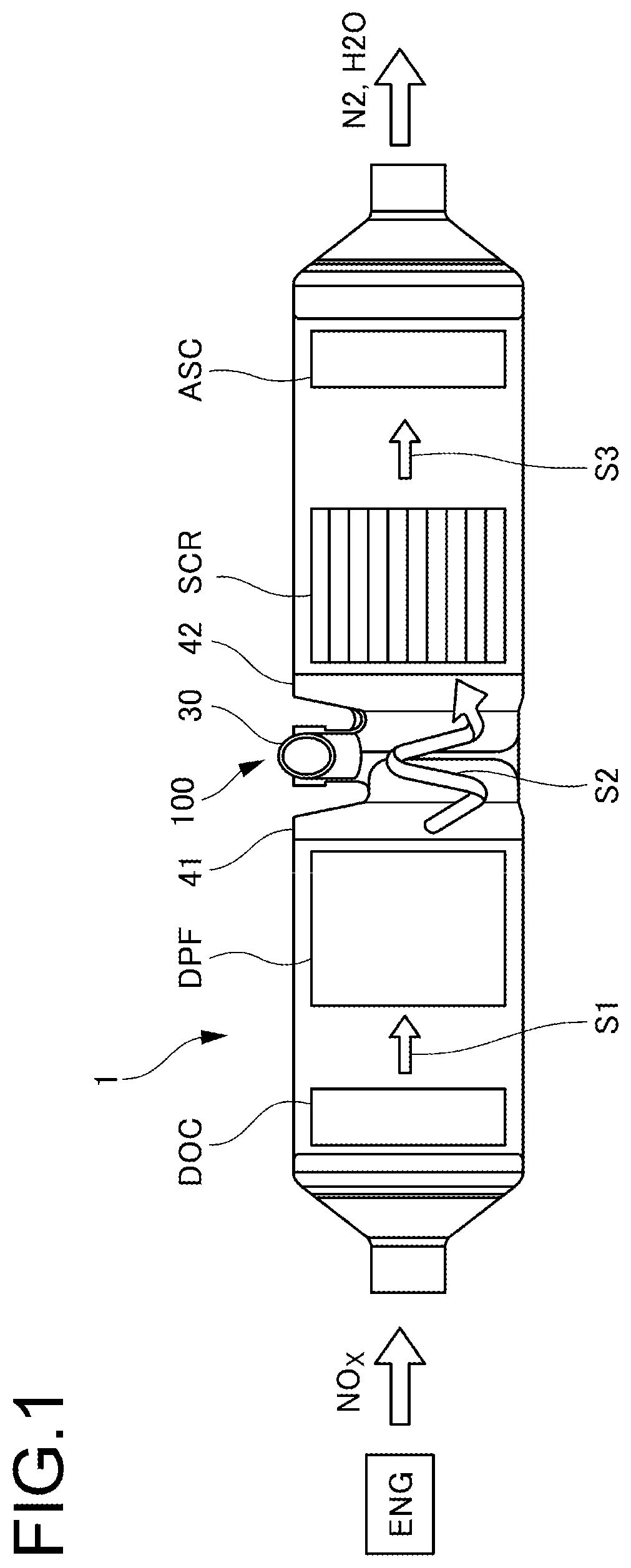
This patent application is a continuation of International Application No. PCT/JP2019/019495 filed May 16, 2019, and claims priority to Japanese Patent Application No. 2018-094778 filed May 16, 2018, the disclosures of which are hereby incorporated by reference in their entirety. Embodiments described herein relate generally to an exhaust gas purification device. A urea selective catalytic reduction (SCR) system has been known as an exhaust gas purification device for an internal combustion engine such as a diesel engine. The urea SCR system includes an injector that injects urea water as a reducing agent into an exhaust flow path, and a reduction catalyst arranged downstream of the injector in the exhaust flow path. In the conventional urea SCR system, when the injector injects urea water into the exhaust gas, the injected urea water undergoes a thermal decomposition and hydrolysis to produce ammonia (NH3). Nitrogen oxides (NOx) in the exhaust gas are reduced by the produced NH3to nitrogen (N2) and water (H2O) in the reduction catalyst. In this manner, the conventional exhaust gas purification device selectively reduces NOx in the exhaust gas to purify it, thereby making the exhaust gas harmless. There is also a conventional exhaust gas purification device in which a mixer having a helical exhaust flow path is located upstream of the reduction catalyst, and a reducing agent is injected into the exhaust flow path to promote mixing of the exhaust gas and the reducing agent (reference may be had to, for example, Japanese Laid-Open Patent Publication No. 2014-190177). However, for example, in the conventional exhaust gas purification device as described above, the mixer needs a complex structure to increase the homogeneity of the reducing agent in the exhaust gas, resulting in an increase in its size. In addition, the pressure loss of the exhaust gas becomes greater, which increases the back pressure on the internal combustion engine. Thus, the degree of freedom decreases in the design of the entire vehicle, which is not preferable. In general, according to one embodiment, an exhaust gas purification device includes: a selective catalytic reduction device located in a downstream exhaust flow path; and a mixer located upstream of the selective catalytic reduction device and including a helical flow path that helically guides a flow of exhaust gas from an internal combustion engine. The mixer includes a casing, a partition plate, and an injector. The casing includes a cylindrical first case that forms an upstream opening on one end, and a cylindrical second case that forms a downstream opening on one end. Another end of the first case is coupled to another end of the second case. The casing has a cylindrical inner space where the upstream opening and the downstream opening directly communicate with each other. The partition plate is formed of a piece separate from the casing, and coupled to the first case and the second case. The partition plate is configured to divide the cylindrical inner space of the casing into an upstream side and a downstream side so as to define the helical flow path in the cylindrical inner space of the casing. The injector is configured to add a reducing agent to the helical flow path. In the following, illustrative embodiments will be described in detail with reference to the accompanying drawings. Note that like parts are designated by like reference numerals or characters throughout the description of the embodiments. The exhaust gas purification device 1 of the embodiment is a device that purifies exhaust gas discharged from an internal combustion engine ENG such as a diesel engine, and is installed downstream of the flow of the exhaust gas. The exhaust gas purification device 1 is, for example, a selective catalytic reduction (SCR) purification system that selectively reduces nitrogen oxides NOx in the exhaust gas discharged from the internal combustion engine ENG using urea water (urea aqueous solution) as a reducing agent. As illustrated in Specifically, the exhaust gas purification device 1 includes a diesel oxidation catalyst DOC arranged in the upstream exhaust flow path S1, a diesel particulate filter DPF arranged in the upstream exhaust flow path S1, and a selective catalytic reduction system SCR that supports a reduction catalyst, which is arranged in the downstream exhaust flow path S3. The exhaust gas purification device 1 may further include, as appropriate, an ammonia slip catalyst ASC. The ammonia slip catalyst ASC is an oxidation catalyst and is arranged downstream of the selective catalytic reduction system SCR in the downstream exhaust flow path S3 to prevent ammonia NH3 from passing through and being released into the outside air. The oxidation catalyst DOC oxidatively purifies hydrocarbon HC and carbon monoxide CO, which are harmful components in the exhaust gas. The oxidation catalyst DOC may be a ceramic honeycomb, a metal mesh, or the like coated with a catalyst component such as platinum or palladium that promotes the oxidation of hydrocarbon HC and carbon monoxide CO. The diesel particulate filter DPF is a filter that collects or removes particulate matter from the exhaust gas. The selective catalytic reduction system SCR may be made from a porous ceramic substrate such as, for example, cordierite, which is coated with a catalyst such as zeolite, vanadium oxide, or tungsten oxide. The exhaust gas purification device 1 includes a mixer 100 that is arranged upstream of the selective catalytic reduction system SCR that supports a reduction catalyst. The mixer 100 is provided with a helical flow path S2 that helically guides the flow of exhaust gas from the internal combustion engine ENG. The mixer 100 includes an injector 30 that injects urea water as a reducing agent into the helical flow path S2. In the exhaust gas purification device 1, when the injector 30 injects urea water into the exhaust gas flowing through the helical flow path S2, the injected urea water undergoes a thermal decomposition and hydrolysis to produce ammonia NH3. As a result, nitrogen oxides NOx in the exhaust gas are reduced by the produced ammonia NH3 to nitrogen N2 and water H2O in the selective catalytic reduction system SCR. The nitrogen N2 and water H2O are released into the outside air. In this manner, the exhaust gas purification device 1 selectively reduces nitrogen oxides NOx in the exhaust gas to purify it, thereby making the exhaust gas harmless. Next, the mixer 100 will be described in detail. As illustrated in By virtue of this configuration of the mixer 100, even if the helical flow path S2 is short (even if the inner space of the casing 20 is narrow or the distance from an upstream opening 21 In the following, each part of the mixer 100 will be described. The casing 20 and the partition plate 10 of the mixer 100 will be described mainly with reference to As illustrated in The casing 20 includes an upstream casing 21 and a downstream casing 22. The upstream casing 21 and the downstream casing 22 have the upstream opening 21 The upstream opening 21 As illustrated in Besides, the upstream opening 21 The length of the helical flow path S2, i.e., the length of the line running from the center of the upstream opening 21 Specifically, the upstream opening 21 As illustrated in The downstream opening 22 Further, the upstream opening 21 Besides, the overlapping portion is formed in the center of the casing 20 as viewed in the flow direction. Thereby, the upstream opening 21 The injector 30 is located on the upper part of the casing 20 so as to protrude into the helical flow path S2 to add a reducing agent to the helical flow path S2. The injector 30 will be described later. The mixer 100 includes, in the casing 20, the partition plate 10 that is continuous from the upstream opening 21 With this, the exhaust gas from the upstream exhaust flow path S1 passes through the upstream opening 21 Specifically, the partition plate 10 is continuous from the left part of the upstream opening 21 The partition plate 10 includes the upstream connection portion 11 connected to the upstream opening 21 The partition plate 10 is connected in an airtight manner to the casing 20 except for the upper end of the gate valve 13. Specifically, the upstream connection portion 11 and the downstream connection portion 12 are connected in an airtight manner to the upstream casing 21 and the downstream casing 22, respectively. The upstream and downstream sides of the lower end of the partition plate 10 are connected in an airtight manner to the upstream casing 21 and the downstream casing 22, respectively. Further, the upstream and downstream ends of the gate valve 13 are connected in an airtight manner to the upstream casing 21 and the downstream casing 22, respectively. The upstream connection portion 11 is connected to the left part, i.e., a part on the left side of the vertical center line CL in the upstream opening 21 Similarly, the downstream connection portion 12 is connected to the right part, i.e., a part on the right side of the vertical center line CL in the downstream opening 22 As illustrated in As illustrated in As mentioned above, the upstream opening 21 Besides, as viewed in the flow direction, the partition plate 10 is substantially symmetrical in the horizontal direction about the vertical center line CL of the portion where the upstream opening 21 The gate valve 13 is a plate-like tongue piece that prevents backflow, and is arranged in the upper part of the partition plate 10. The gate valve 13 is located in a transition portion between the upstream side and the downstream side in the inner space of the casing 20. The gate valve 13 extends across the upstream casing 21 and the downstream casing 22, and the upstream end is connected to the right part of the upstream opening 21 The pressure loss suppression hole 14 is a hole that allows the exhaust gas to pass from upstream to downstream. Specifically, the pressure loss suppression hole 14 allows the exhaust gas from the upstream exhaust flow path S1 to flow directly to the downstream exhaust flow path S3 without passing through the helical flow path S2, thereby reducing the pressure loss due to exhaust (smoothing changes in pressure). The pressure loss suppression hole 14 is located in substantially the center of the casing 20 as viewed in the flow direction. Besides, the pressure loss suppression hole 14 is arranged in the upper part of the partition plate 10. As illustrated in Next, the injector 30 will be described mainly with reference to The injector 30 is a device to add a reducing agent such as urea water to the helical flow path S2. As illustrated in The injector main body 31 is cylindrical with open ends, and is arranged such that the axial center thereof extends along the injection direction INJ of the reducing agent from the nozzle and the helical flow path S2. The injector main body 31 has the intake opening 35 at the bottom with respect to the injection direction INJ in the center in the longitudinal direction. Thus, the reducing agent ejected from the nozzle enters through the opening at one end of the injector main body 31 and exits through the opening at the other end. At the same time, the exhaust gas from the upstream side of the helical flow path S2 enters from the intake opening 35 and passes out of the opening at the other end. The nozzle attachment portion 32 includes a flange having a central opening that serves as a path of the reducing agent ejected from the nozzle and a plurality of attachment holes in the periphery. The nozzle is attached to the flange of the nozzle attachment portion 32 with a bolt or the like. Thereby, the positional relationship between the nozzle and the injector 30 can be reliably defined. As illustrated in The collision plate 33 may have a length extending from the inner wall of the injector main body 31 to the vicinity of the axial center of the injector main body 31 (near the injection direction INJ in The collision plate 33 is formed by cutting a part of the peripheral wall of the injector main body 31 into a U shape and folding the cut part toward the inside of the injector main body 31 at an acute angle (for example, an angle of 10 to 60 degrees). The collision plate 33 is arranged such that the fold line is located upstream and the free end is located downstream in the injection direction INJ of the reducing agent. A portion of the injector main body 31 adjacent to the collision plate 33 is an opening having substantially the same shape as the collision plate 33. Note that the collision plate 33 need not necessarily be formed by cutting a part of the peripheral wall of the injector main body 31 as described above. A separate plate may be fixed as the collision plate 33 to the inner wall of the injector main body 31 by welding or the like. In this case, the injector main body 31 does not need an opening having substantially the same shape as the collision plate 33 in a portion adjacent to the collision plate 33. As illustrated in As illustrated in The plurality of collision plates 33 arranged on the peripheral wall of the injector main body 31 can be formed as follows: integrally forming the collision plates 33 as a part, and then fixing the part to the peripheral wall of the injector main body 31 by appropriate means such as welding. The control blade 34 is configured to diffuse the reducing agent ejected from the nozzle, including the reducing agent broken up into fine droplets by the collision plate 33, into the exhaust gas in the helical flow path S2. As illustrated in The free end of the rectifying blade 34 The free end of the intersecting blade 34 Therefore, the exhaust gas and the reducing agent that pass through the injector main body 31 are rectified to flow straight by the flat surface in the free end of the rectifying blade 34 With the control blade 34, the added reducing agent can be broken up into fine droplets. In addition, the thermal decomposition and hydrolysis of the reducing agent can be promoted to generate a helical flow of the fine droplets of the reducing agent. Thus, the reducing agent can be diffused and mixed in the exhaust gas passing through the helical flow path S2. Moreover, the reducing agent can be prevented from remaining attached to the inner wall of the casing 20 because of the high flow rate. Therefore, the nitrogen oxides NOx in the exhaust gas can be efficiently reduced in a short flow distance, i.e., in a limited narrow space. In the embodiment, two intersecting blades 34 Next, the reducer 40 will be described mainly with reference to As illustrated in The upstream reducer 41 includes an upstream reducer inlet 41in having a cross section equivalent to the cross section of the upstream exhaust flow path S1, and an upstream reducer outlet 41out having a cross section equivalent to the cross section of the upstream opening 21 The upstream reducer inlet 41in and the upstream reducer outlet 41out are arranged such that their cross sections are substantially parallel to each other. The cross section of the upstream reducer outlet 41out is smaller than that of the upstream reducer inlet 41in. As with the upstream opening 21 The upstream reducer 41 is formed so as to connect the upstream reducer inlet 41in and the upstream reducer outlet 41out. The upstream reducer 41 has a side wall 41 Since the upstream reducer 41 has a funnel-like shape as a whole, the flow rate is increased as the flow path becomes narrower. Thereby, the exhaust gas from the upstream exhaust flow path S1 can be smoothly guided to the inside of the casing 20 with less pressure loss while the flow is being deflected to change its direction. On the other hand, the downstream reducer 42 includes a downstream reducer inlet 42in having a cross section equivalent to the cross section of the downstream opening 22 The downstream reducer inlet 42in and the downstream reducer outlet 42out are arranged such that their cross sections are substantially parallel to each other. The cross section of the downstream reducer outlet 42out is larger than that of the downstream reducer inlet 42in. As with the downstream opening 22 The downstream reducer 42 is formed so as to connect the downstream reducer inlet 42in and the downstream reducer outlet 42out. The downstream reducer 42 has a side wall 42 Since the downstream reducer 42 has a funnel-like shape as a whole, the flow path gradually becomes wider. Thereby, the exhaust gas from the helical flow path S2 can be smoothly guided to the downstream exhaust flow path S3 with less pressure loss. The operation of the exhaust gas purification device 1 until the exhaust gas is purified thereby will be described along the flow of exhaust gas. As illustrated in Subsequently, the exhaust gas guided to the exhaust gas purification device 1 passes through the oxidation catalyst DOC located in the upstream exhaust flow path S1. At this time, hydrocarbon HC and carbon monoxide CO, which are harmful components in the exhaust gas, are oxidatively purified by the oxidation catalyst DOC. After passing through the oxidation catalyst DOC, the exhaust gas passes through the diesel particulate filter DPF located in the upstream exhaust flow path S1. At this time, the diesel particulate filter DPF collects or removes particulate matter from the exhaust gas. Having passed through the diesel particulate filter DPF, the exhaust gas is guided to the mixer 100. In the mixer 100, first, the flow of the exhaust gas that has passed through the diesel particulate filter DPF is deflected by the upstream reducer 41, and the flow rate increases. After passing through the upstream reducer 41, the exhaust gas flows helically along the helical flow path S2 defined by the casing 20 and the partition plate 10. At this time, part of the exhaust gas that has passed through the upstream reducer 41 flows directly from the upstream side to the downstream side through the pressure loss suppression hole 14. This reduces the concentration of pressure around the pressure loss suppression hole 14. Thereby, the pressure distribution inside the casing 20 can be made uniform. When the exhaust gas flowing along the helical flow path S2 has passed through a transition portion (near the gate valve 13 of the partition plate 10) between the upstream side and the downstream side in the casing 20, part of the exhaust gas that has passed through the transition portion passes through the intake opening 35 and reaches the inside of the injector main body 31. At the same time, the urea water, which has been turned into a fine spray or mist as being ejected from the nozzle attached to the injector 30, collides with the collision plate 33 arranged so as to protrude to the inside of the injector main body 31, and is further broken up into fine droplets. The urea water also undergoes a thermal decomposition and hydrolysis to produce ammonia NH3. The produced ammonia NH3 merges with the exhaust gas that has reached the inside of the injector main body 31. Then, they reaches the control blade 34 while being mixed with each other. Having reached the control blade 34, the exhaust gas and ammonia NH3 are divided into rectified and helical flows by the control blade 34, and are mixed homogeneously without a large drop in flow rate. The exhaust gas and ammonia NH3 mixed with each other flow helically as being mixed more homogeneously while maintaining the flow rate, and exit from the casing 20 to reach the downstream reducer 42. Having reached the downstream reducer 42, the flow of the exhaust gas and ammonia NH3 mixed with each other is gradually deflected by the downstream reducer 42 and turns from a helical flow along the helical flow path S2 Having passed through the downstream reducer 42, the exhaust gas and ammonia NH3 mixed with each other pass through the selective catalytic reduction system SCR located in the downstream exhaust flow path S3. The nitrogen oxides NOx and ammonia NH3 in the exhaust gas that have reached the selective catalytic reduction system SCR are reduced by the catalyst supported on the selective catalytic reduction system SCR to nitrogen N2 and water H2O. After passing through the selective catalytic reduction system SCR, the exhaust gas reaches the ammonia slip catalyst ASC located downstream of the selective catalytic reduction system SCR in the downstream exhaust flow path S3. The ammonia slip catalyst ASC removes leftover ammonia NH3 from the exhaust gas that has passed through the selective catalytic reduction system SCR. Then, the nitrogen N2 and water H2O are appropriately released into the outside air. In this manner, the exhaust gas purification device 1 efficiently purifies nitrogen oxides NOx in the exhaust gas to make the exhaust gas harmless. Thus, the exhaust gas purification device 1 can be made compact as a whole. While preferred embodiments have been illustrated and described, the disclosure is not limited to these embodiments. Numerous modifications and variations may be made without departing from the spirit and scope of the disclosure as described in the claims. According to the embodiment, an exhaust gas purification device (1) includes: a selective catalytic reduction device (SCR) arranged in a downstream exhaust flow path (S3); and a mixer (100) arranged upstream of the selective catalytic reduction device (SCR) and including a helical flow path (S2) that helically guides the flow of exhaust gas from an internal combustion engine (ENG). In the exhaust gas purification device (1), the mixer (100) includes: a casing (20) having an upstream opening (21 Next, modifications of the embodiment will be described with reference to The casing 20 includes the upstream casing 21 and the downstream casing 22. The upstream casing 21 has the upstream opening 21 As illustrated in The mixer 101 of the modification is different from the mixer 100 in the position where the injector 130 is located and in that the orientation of the injector 130 is inclined. The injector main body 131 is cylindrical with open ends, and is arranged such that the axial center thereof extends along the injection direction INJ of the reducing agent from the nozzle. Besides, the injector 130 is arranged such that the axial center thereof is inclined toward the downstream opening 22 In the mixer 100 described above, the partition plate 10 is provided with the pressure loss suppression hole 14. The pressure loss suppression hole 14 includes one hole in the center and six holes around it. A total of seven holes are arranged side by side at equal pitches such that lines connecting the centers of the six holes form a regular hexagon. In the mixer 101 of the modification, the partition plate 10 is provided with a pressure loss suppression hole 114 including a total of 13 holes: a row of seven holes and a row of six holes. In the mixer 100 described above, the upstream reducer 41 and the downstream reducer 42 include the flange 41 The mixer 100 described above includes the gate valve 13 that prevents the backflow, while the mixer 101 of the modification is configured without the gate valve for preventing the backflow. As indicated by the broken line in While certain embodiments have been illustrated and described herein, it is to be understood that the scope of the inventions is not limited to the specific embodiments. As would be apparent to those skilled in the art, various changes, modifications, and alterations may be made without departing from the spirit and scope of the disclosure as described in the claims. An exhaust gas purification device includes a selective catalytic reduction (SCR) device arranged in a downstream exhaust flow path, and a mixer arranged upstream of the selective catalytic reduction device and including a helical flow path that helically guides the flow of exhaust gas from an internal combustion engine. In the exhaust gas purification device, the mixer includes a casing, an injector, and a partition plate. The casing has an upstream opening and a downstream opening and is provided with the helical flow path therein. The injector is arranged in the helical flow path to add a reducing agent to the helical flow path. The partition plate is continuous from the upstream opening to the downstream opening. The partition plate is arranged to divide the inner space of the casing into an upstream side and a downstream side, and defines the helical flow path. 1. An exhaust gas purification device comprising:
a selective catalytic reduction device located in a downstream exhaust flow path; and a mixer located upstream of the selective catalytic reduction device, wherein the mixer comprises:
a helical flow path that helically guides a flow of exhaust gas from an internal combustion engine, a casing comprising a cylindrical first case that forms an upstream opening on one end, and a cylindrical second case that forms a downstream opening on one end, wherein another end of the first case is coupled to another end of the second case, the casing having a cylindrical inner space where the upstream opening and the downstream opening directly communicate with each other, a partition plate formed of a piece separate from the casing and coupled to the first case and the second case, the partition plate configured to divide the cylindrical inner space of the casing into an upstream side and a downstream side so as to define the helical flow path in the cylindrical inner space of the casing, and an injector configured to add a reducing agent to the helical flow path. 2. The exhaust gas purification device according to the upstream opening is narrower than an upstream exhaust flow path from the internal combustion engine, and the downstream opening is narrower than the downstream exhaust flow path. 3. The exhaust gas purification device according to 4. The exhaust gas purification device according to 5. The exhaust gas purification device according to 6. The exhaust gas purification device according to 7. The exhaust gas purification device according to 8. The exhaust gas purification device according to 9. The exhaust gas purification device according to 10. The exhaust gas purification device according to 11. The exhaust gas purification device according to 12. The exhaust gas purification device according to CROSS-REFERENCE TO RELATED APPLICATIONS
BACKGROUND
Field of the Disclosure
Description of Related Art
BRIEF DESCRIPTION OF THE DRAWINGS
DETAILED DESCRIPTION
Embodiments
(Mixer 100)
(Casing 20 and Partition Plate 10)
(Injector 30)
(Reducer 40)
(Operation of the Exhaust Gas Purification Device 1)
(Injector 130)