ASSEMBLY OF CABLE TRAYS
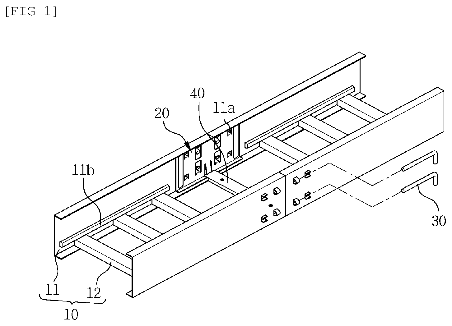
The present invention relates to an assembly of cable trays and, more particularly, to an assembly of cable trays capable of reducing a manufacturing cost by allowing a load to be reinforced and maintained simply by a L-shaped pin assembly structure without using bolts for a vertical load and a horizontal load when coupling cable trays with a connecting member. Generally, big and small diameter cables are arranged along a ceiling and a floor or a wall for supply of power or fluid to a factory, a ship, and an offshore structure, and the cables arranged in this way are supported and fixed by using cable trays to avoid spoiling the aesthetics or inconveniencing passengers. A conventional cable tray for supporting and fixing various cables as described above is configured largely to include: a pair of side frames positioned on left and right sides, respectively, with a predetermined length; and hangers (rod-shaped, plate-shaped) each coupled to the side frames at regular intervals between the side frames. In addition, since the cable tray has the predetermined length in the longitudinal direction, a plurality of cable trays is connected using connecting members, thereby being allowed to be arranged along the ceiling or wall of a building. An example of such a cable tray can be found in the “ASSEMBLY OF CABLE TRAY” of the Korea Patent No. 10-1266615. The assembly of cable trays may include a resilient insertion piece formed in a connecting member for connecting the side frames arranged in succession in the longitudinal direction, and a fixing member coupled to the slot formed by protrusion of the resilient insertion piece, whereby adhesiveness of the connecting member for connecting the cable trays is improved, and the clearance of the fixing member for fixing the cable trays and the connecting member can be minimized. However, in the conventional assembly of cable trays, a plurality of fixing members (four pieces) is required to be fixed to the connecting members for connecting the cable trays, which causes a manufacturing cost to be increased. Meanwhile, when the number of the fixing members is reduced, a load with respect to the vertical load and the horizontal load cannot be mitigated. (Patent Document 1) Korean Patent No. 10-1266615, (Registration Date: May 15, 2013) Accordingly, the present invention is to solve the problems of the conventional art described above, and it is an object of the present invention to provide an assembly of cable trays capable of reducing a manufacturing cost by allowing a load to be reinforced and maintained simply by a L-shaped pin assembly structure without using bolts for a vertical load and a horizontal load when coupling cable trays with a connecting member. In addition, the assembly of the cable trays according to the present invention is to provide the assembly of the cable trays, which is configured not only to strengthen the strength of side frames but also to allow the side frames to be easily coupled with a rung. Further, the assembly of the cable trays according to the present invention is configured to provide a connection block for reinforcing against the widening of a gap between the side frames and the rung, thereby allowing the connection block to strengthen the strength of the assembly while assembling the assembly in a simple manner and preventing the cable from sagging during routing thereof. In order to achieve the above object, according to one aspect of the present invention, there is provided an assembly of cable trays, the assembly including: a cable tray including a pair of side frames spaced apart from each other at a predetermined distance at left and right sides, respectively, the pair of side frames each having a plurality of through holes formed at opposite ends in the longitudinal direction thereof; a connecting member interconnecting the side frames in order to arrange the cable trays in succession in the longitudinal direction; and a fixing member fixing the cable trays and the connecting member after the connecting member is allowed to be brought into close contact with the inner side of the cable trays, wherein the connecting member is configured: to form a pair of protruding insertion pieces integrally at the upper and lower portions, respectively, in the middle thereof; to allow the fixing member to be coupled with a slot formed by a protrusion of the protruding insertion piece; and to allow a clip portion to be formed in an outer side direction of each of the protruding insertion pieces, thereby being supported by the through hole of the cable tray. In addition, the assembly may be configured to couple rungs with the side frames at regular distances, wherein, by allowing a holding portion to be formed in a horizontal direction in each of the side frames, the rungs are coupled to be brought into close contact with a side below the holding portion. In addition, the fixing member may be configured to be a semicircle. In addition, the connecting members installed at the left and right sides, respectively, and spaced apart from each other at a predetermined distance may be connected by a connecting block, wherein opposite ends in a longitudinal direction of the connecting block are allowed to be fixed to slots each formed in the horizontal direction at a lower portion in the middle of each of the connecting members, correspondingly. In addition, the protruding insertion piece may be configured to have one end thereof integrally formed at a main body of the connecting member and the other end thereof separated to form the free end. In addition, the side frames may be coupled with rungs at regular distances, each of the side frames includes a protruding hook protruding inwardly thereon to support the top end of the rung, the rung has at least one latch bent downward at each of opposite ends in a longitudinal direction thereof, and the side frame and the rung are connected by a fixing means. In addition, the protruding hook may be configured to be in contact with the top surface of the rung over a part or all of a rung width. In addition, the protruding hook may be configured to be at least one piece. In addition, the protruding hook may be configured to be formed by a press process. In addition, protruding rims may be formed on the end portions of the top surface of opposite ends in the longitudinal direction of the rung in a process of being subjected to a cutting process of the rung and are in contact with a portion of the protruding hook. In addition, a depression groove may be formed in a central portion of the rung width at each of opposite ends in the longitudinal direction of the rung, the depression groove is formed long in the longitudinal direction over the latch and the top portion of the rung, and a whole length of the depression groove does not exceed twice the height of the latch. In addition, the latch may include a clip seating groove being installed with a bolt hole, with a perimeter of the bolt hole being protruded and formed integrally with the latch, and further having screw threads. In addition, the assembly may be configured to have a separation distance between the side frame and the latch when the side frame and the rung are connected by the fixing means. In addition, the separation distance between the side frame and the latch may be, with the lower end of the latch being as a reference, ½ to no more than 5 times the thickness of the rungs in a state before the fixing means is connected. As a concept to accomplish the present invention, the assembly of the cable trays according to the present invention is configured to allow a pair of protruding insertion parts along with a pair of clip portions to be formed at the upper and lower portions, respectively, in the middle of a connecting member interconnecting adjacent side frames to arrange the cable trays in succession in the longitudinal direction. Thus, the assembly of the cable trays is capable of reducing manufacturing cost by allowing a load to be reinforced and maintained simply by an L-shaped pin assembly structure without using bolts for a vertical load and a horizontal load when coupling cable trays with a connecting member. Further, it is possible to prevent a gap in the assembly of the cable trays from widening, thereby preventing the cable from sagging, reinforcing the load strength, and coupling the fixing member readily. In addition, the assembly of the cable trays according to the present invention is configured to have the holding portion formed in the horizontal direction on each of the side frames thereof, thereby allowing the rung to be brought into close contact with the side under the holding portion. Accordingly, the assembly of the cable trays is configured to strengthen the strength of the side frames as well as to allow the side frames to be readily coupled with the rung. Hereinafter, composition and an operation of embodiments of the present invention will be described with reference to the accompanying drawings. With reference to The cable tray 10 includes a pair of side frames 11 spaced apart from each other at a predetermined distance at left and right sides, respectively, the pair of side frames 11 each having a plurality of through holes 11 Here, the side frames 11 may be connected by a plurality of rungs 12 or plate structures connecting the side frames 11. In the present invention, a state in which the rungs 12 are coupled with the side frames 11 will be described as an example. Meanwhile, the assembly is configured to couple rungs with the side frames at regular distances, wherein, by allowing a holding portion to be formed in a horizontal direction in each of the side frames, and then by coupling the rungs to be brought into close contact with a side below the holding portion, strength of the assembly is reinforced even if a thickness of the side frames is thin. In addition, the holding portion 11 The connecting member 20 interconnects the adjacent side frames 11 in order to arrange the cable trays 10 in succession in the longitudinal direction. In addition, the connecting member 20 is configured: to form a pair of protruding insertion pieces 21 integrally at the upper and lower portions, respectively, in the middle thereof; to allow the fixing member 30 to be coupled with a slot 21 In addition, the protruding insertion piece 21 is configured to have one end thereof integrally formed at a main body of the connecting member 20 and the other end thereof separated to form the free end 21 Further, the clip portion 22 may be passed through as shown in The fixing member 30 is configured to fix the cable trays 10 and the connecting member 20 after the connecting member 20 is allowed to be brought into close contact with the inner side of the cable trays 10. In addition, the fixing member 30 is configured to be a semicircle, thereby entering smoothly when inserted into the slot 21 In addition, the fixing member 30 may be modified in various shapes such as a semi-circle, a circle, a rectangle having a stepped shape formed therein, or the like. In addition, the connecting members 20 installed at the left and right sides, respectively, and spaced apart from each other at a predetermined distance are connected by a connecting block 40, wherein opposite ends in the longitudinal direction of the connecting block 40 are allowed to be fixed to the coupling grooves 23, each formed in the horizontal direction at a lower portion in the middle of each of the connecting members 20, correspondingly, thereby allowing the clearance and the coupling force of the connecting members 20 to be improved. Further, a distance between the rungs 12 may be widened due to the portion where the connecting member 20 is coupled, thereby causing the load strength of the assembly of the cable trays to be decreased. However, it is possible to reinforce the load strength by the connecting block 40, and even when the rung is composed of the plate, it is also possible to protect a gap between the plates or to prevent a bird caging from occurring, thereby allowing the cable to be protected. In addition, it is possible to shorten the distance between the rung 12 of a first tray and the rung 12 of a second tray by assembling the connection block 40 concisely, thereby preventing the cable from sagging, reinforcing the load strength, and easily coupling the fixing member 30. Meanwhile, With reference to Meanwhile, the rung 12 has latches 12 In addition, the protruding hook 11 Accordingly, the protruding hook 11 In addition, rims 12 In addition, a depression (a) groove 12 Meanwhile, the groove 12 In addition, the fixing means 13 for the side frame 11 and the rung 12 may use any one of a bolt and a rivet, and is preferable to allow the latch to include a clip seating groove 12 In addition, in order to prevent the bolt from being loosened due to the small number of screw threads of the bolt hole 12 The assembly of the cable trays 100 according to the present invention as described above is configured to connect the side frames 11, adjacent to each other, of the cable trays 10 in order to interconnect the cable trays 10 in succession in the longitudinal direction, whereby the protruding insertion piece 21 and the clip portion 22 of the connecting member 20 are inserted into the plurality of through holes 11 In addition, when the fixing member 30 is coupled to the slot 21 At this time, the clip portion 22 formed on the outer side direction of the protruding insertion piece 21 is supported by the through hole 11 In addition, when the fixing member 30 is coupled to the protruding insertion piece 21, the elasticity of the protruding insertion piece 21 may be improved by the free end 21 In addition, the rungs 12 are coupled to the side under the holding portion 11 In addition, as another embodiment of the holding portion 11 In addition, each of the connecting members 20 installed at the left and right sides and spaced apart from each other at a predetermined distance is connected to the connecting block 40, thereby fixing each of the opposite ends in the longitudinal direction of the connecting block 40 to the coupling grooves 23 formed at a lower portion in the middle of each of the connecting members 20, correspondingly. While the invention has been described with reference to an embodiment thereof, it will be understood by those skilled in the art that various changes and modifications may be made therein without departing from the spirit and scope of the invention as defined by the appended claims. An object of the present invention is to provide an assembly of cable trays capable of reducing a manufacturing cost by allowing a load to be reinforced and maintained simply by an L-shaped pin assembly structure when coupling cable trays with a connecting member. The assembly of cable trays includes a cable tray, a connecting member, and a fixing member. Meanwhile, the connecting member is configured to allow: a pair of protruding insertion pieces to be integrally formed at the upper and lower portions, respectively, in the middle thereof; the fixing member to be coupled with a slot formed by the protrusion of the protruding insertion piece; and a clip portion to be formed in an outer side direction of each of the protruding insertion pieces so as to be supported by the through hole of the cable tray. 1. An assembly of cable trays, the assembly comprising:
a cable tray including a pair of side frames spaced apart from each other at a predetermined distance at left and right sides, respectively, the pair of side frames each having a plurality of through holes formed at opposite ends in the longitudinal direction thereof; a connecting member interconnecting the side frames in order to arrange the cable trays in succession in the longitudinal direction; and a fixing member fixing the cable trays and the connecting member after the connecting member is allowed to be brought into close contact with the inner side of the cable trays, wherein the connecting member is configured: to form a pair of protruding insertion pieces integrally at the upper and lower portions, respectively, in the middle thereof; to allow the fixing member to be coupled with a slot formed by a protrusion of the protruding insertion piece; and to allow a clip portion to be formed in an outer side direction of each of the protruding insertion pieces, thereby being supported by the through hole of the cable tray. 2. The assembly of 3. The assembly of 4. The assembly of 5. The assembly of 6. The assembly of 7. The assembly of 8. The assembly of 9. The assembly of 10. The assembly of 11. The assembly of a depression groove is formed in a central portion of the rung width at each of opposite ends in the longitudinal direction of the rung, the depression groove is formed long in the longitudinal direction over the latch and the top portion of the rung, and a whole length of the depression groove does not exceed twice the height of the latch. 12. The assembly of 13. The assembly of 14. The assembly of TECHNICAL FIELD
BACKGROUND ART
RELATED ART DOCUMENT
DISCLOSURE
Technical Problem
Technical Solution
Advantageous Effects
DESCRIPTION OF DRAWINGS
MODE FOR INVENTION