ELECTRONICALLY COMMUTATED ROTATING ELECTRICAL MACHINE
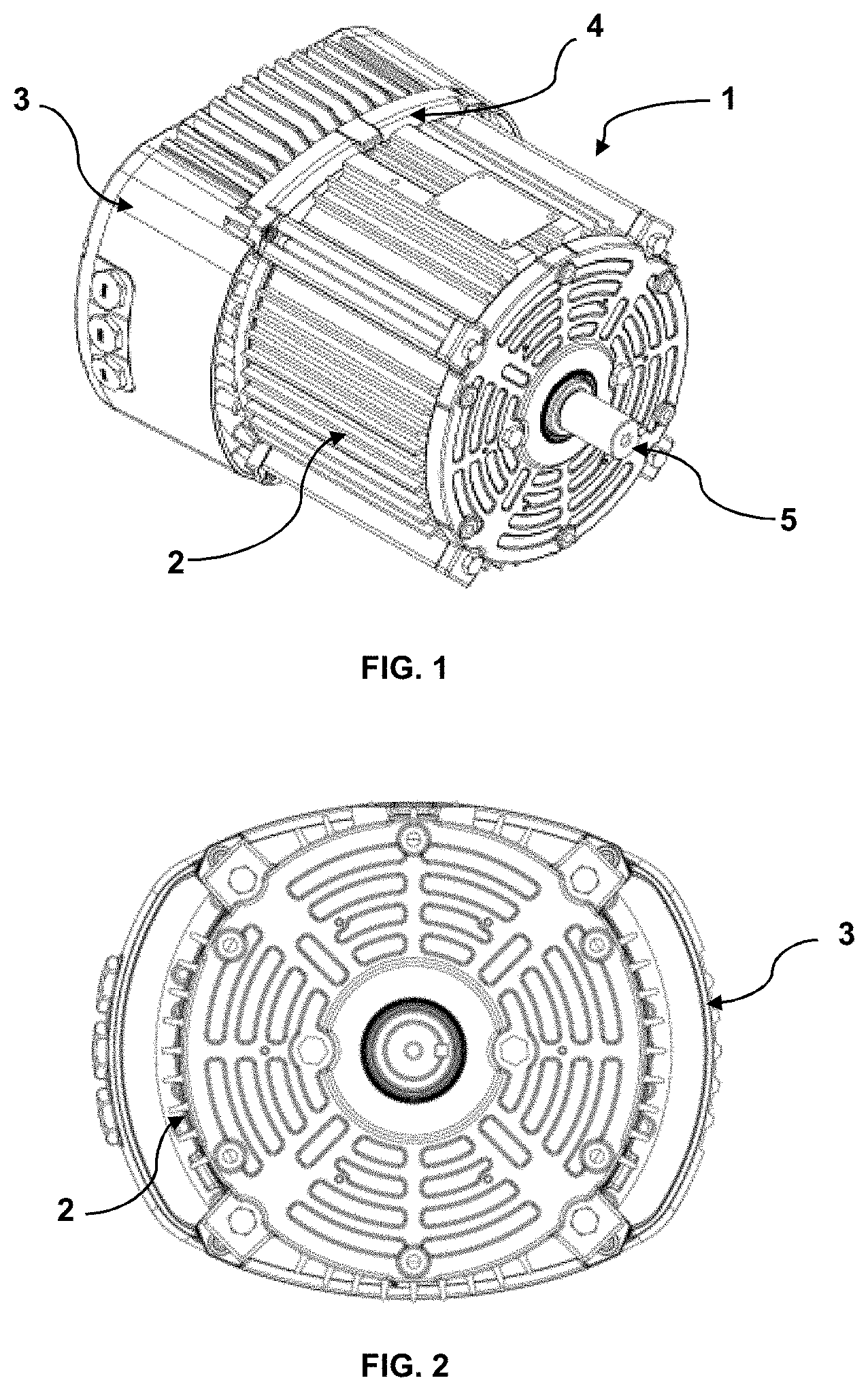
This application claims the benefit of U.S. Provisional Application Ser. No. 62/945,766, filed Dec. 9, 2019, said application herein incorporated by reference in its entirety. The present invention relates to an electronically commutated rotating electric machine, and more specifically, to a heat dissipating solution for an electronically commutated rotating electric machine. Electronically commutated rotating electric machines, such as electronically commutated motors (EC motors), are machines that use an electronic control drive for varying machine speed. EC motors comprise a housing with a first housing part for housing the motor components and a second housing part for housing the drive. One of the challenges associated with electronically commutated rotating electric machines is related to the temperature reached by the machines. In fact, both engine components and electronic control components generate heat during operation, so it is necessary to develop some type of ventilation solution to cool components and prevent malfunctions and malfunctions. One of the well-known solutions for cooling ECM machines is to provide air inlet and outlet openings in the housing to allow air to circulate and cool the components by heat exchange. Another known solution is described in document US10291102B2, which describes a motor including a housing, a front cover and a fan, in which the front cover is formed with air inlet holes and with air guiding fins. Another solution is described in document EP3043450, which discloses a motor with a substantially cylindrical housing and a cooling fan. The motor also includes a sleeve fitted around the housing and formed integrally with a plurality of wind capture projections to receive the air flow induced by the cooling fan. Document EP2973957 shows yet another ventilation solution, in which the electrical machine includes a housing with at least one air inlet, one air outlet and an air passage that extends between at least one air inlet and the air outlet. The electric machine also includes a first heat sink positioned at least partially within the air passage and a second heat sink positioned at least partially within the air passage downstream of the first heat sink. A flow of cooling air through the at least one air inlet flows through the air passage to cool the first heat sink and the second heat sink before the cooling air flow is exhausted by the air outlet. WO2004023628, in turn, describes an electric motor cooling solution, in which the motor comprises a first housing having a first wall defining a first interior space and at least one opening arranged on a surface of the first housing; a second compartment having a second wall defining a second interior space and at least one opening arranged on a surface of the second compartment. Even though different cooling solutions have been developed, the need for electronically commutated rotating electric machine with a thermal dissipation solution that operates efficiently with air flows in both axial directions, and which is easy to assemble and small in size, remains in the state of the art. It is an object of the present invention to provide an electronically commutated rotating electric machine with an improved thermal dissipation solution. It is another object of the present invention to provide an electronically commutated rotating electric machine with a heat dissipating solution that operates with both axial (bidirectional) air flows. It is yet another object of the present invention to provide an electronically commutated rotating electric machine that is easy to assemble and maintain. It is a further object of the present invention to provide an electronically commutated rotating electric machine having small dimensions. The present invention contemplates an electronically commutated rotating electric machine comprising a first housing part housing the active machine core and a second housing part housing the control drive in accordance with the present invention, wherein: the first and second housing parts are configured such that, after being fixed to one another, a gap is formed between them; the first housing part comprises a rear plate with at least one deflecting portion; the second housing part comprises a front plate comprising at least one deflecting portion; The gap is formed between the rear plate and the front plate, so that the deflecting portions are configured to direct air flow into the gap. In one embodiment of the invention, the deflecting portions are configured in a concave shape. However, the deflecting portions may have any other shapes that allow the air flow to be directed into the gap. The first and second housing parts may be dimensioned such that: a portion of the rear plate surface directly receives an air flow flowing from a rear part of the machine; and a portion of the front plate surface directly receives an air flow flowing from a front of the machine. In one embodiment of the invention, the deflecting portion of the rear plate is formed at the perimeter of said surface portion of the rear plate; and the deflecting portion of the front plate is provided at the perimeter of said surface portion of the front plate. In this sense, an air flow can flow from the front of the machine to the rear, and this flow hits the deflecting portion of the rear part and is directed to the gap formed between the plates. In the deflecting portion of the front plate, a low pressure zone is formed due to the air flow, which helps in exhausting the heated air between the plates. Similarly, an air flow can flow from the rear of the machine to the front, and this flow strikes the deflecting portion of the front and is directed to the gap formed between the plates. In the deflecting portion of the rear plate, a low pressure zone is formed due to the air flow, which helps to exhaust the heated air between the plates. In addition, the front plate may have a plurality of heat exchange projections. Although the figures illustrate an electronically commuted electric motor, it should be understood that the present invention could be applied to any electronically commuted rotating electric machine or any rotating electric machine with incorporated electronics. As can be seen from the figures, the electronically commuted electric machine 1 comprises a first motor housing part 2 and a second control drive housing part 3. Motor housing 2 and control drive 3 parts are configured so that, after being connected to each other to form motor housing 1, a gap is formed between them. The electronically commuted electric machine 1 of the present invention is designed for thermal dissipation to operate with air flow in both axial directions (bidirectional). That is, to allow thermal dissipation to occur with both an air flow flowing from the front of the motor housing part 2 and an air flow flowing from the rear of the control drive housing part 3. To this end, the first and second housing parts 2 and 3 are dimensioned such that a part of the air flow that reaches the machine 1 in one of the axial directions is necessarily directed into the gap formed between the housing parts 1 and 2. In the embodiment shown in the figures, the motor housing part 2 comprises a body with fins with a front housing part, which may for example be a front cover with a housing end with a shaft through hole 5, and a rear plate 4, which preferably has a concave shape and at least one deflecting portion 4 Control drive housing portion 3 comprises a housing body enclosed by a cove or rear housing portion and a front plate 6 comprising at least one deflecting portion 6 The deflecting portions 4 In this sense, the deflecting portion 6 Similarly, an air flow flowing from the rear of the machine hits the rear plate 4 and has a portion directed towards the gap (see arrow S in In this sense, the deflecting portion 4 In one embodiment of the invention, the first and second housing parts are dimensioned so that when the air flow over the machine flows from the rear of the machine, a portion of the rear plate's 4 surface directly receives the air flow flowing from the rear of the machine, and when the air flow over the machine flows from the front of the machine, a portion of the front plate's 6 surface directly receives the air flow flowing from the front of the machine. In this embodiment, the deflecting portion 4 As shown in In the embodiment shown in the drawings, the first and second housing parts are fixed by screws. However, alternative means of attachment could be used within the context of the present invention. Having described an exemplary embodiment of the present invention, it should be understood that the scope of the present invention encompasses other possible variations of the inventive concept described, being limited only by the scope of the appended claims, including the possible equivalents thereof. An electronically commutated rotating electric machine comprising a first housing part, housing the active core of the machine and a second housing part that houses the control drive, wherein the first and second housing parts are configured such that, after being connected to one another, a gap is formed between them; the parts having deflecting portions that are configured to direct an air flow into the gap. 1. An electronically commutated electric rotating machine comprising a first housing part which houses the active core of the machine and a second housing part which houses the drive control, wherein:
the first and second housing parts are configured such that, after being connected to one another, a gap is formed between them; the first housing part comprises a rear plate with at least one deflecting portion; the second housing part comprises a front plate comprising at least one deflecting portion; the gap being formed between the rear plate and the front plate, so that the deflecting portions are configured to direct air flow into the gap. 2. The machine according to 3. The machine according to the first and second housing parts are dimensioned such that: a portion of the surface of the rear plate directly receives an air flow flowing from a rear part of the machine; and a portion of the surface of the front plate directly receives an air flow flowing from a front part of the machine. 4. The machine according to the deflecting portion of the rear plate is formed on the perimeter of said surface portion of the rear plate; and the deflecting portion of the front plate is provided at the perimeter of said surface portion of the front plat. 5. The machine according to CROSS-REFERENCE TO RELATED APPLICATIONS
FIELD OF THE INVENTION
BACKGROUND OF THE INVENTION
SUMMARY OF THE INVENTION
BRIEF DESCRIPTION OF THE INVENTION
BRIEF DESCRIPTION OF THE DRAWINGS
DETAILED DESCRIPTION OF THE INVENTION