THERMALLY INSULATED EXHAUST SYSTEM COMPONENTS
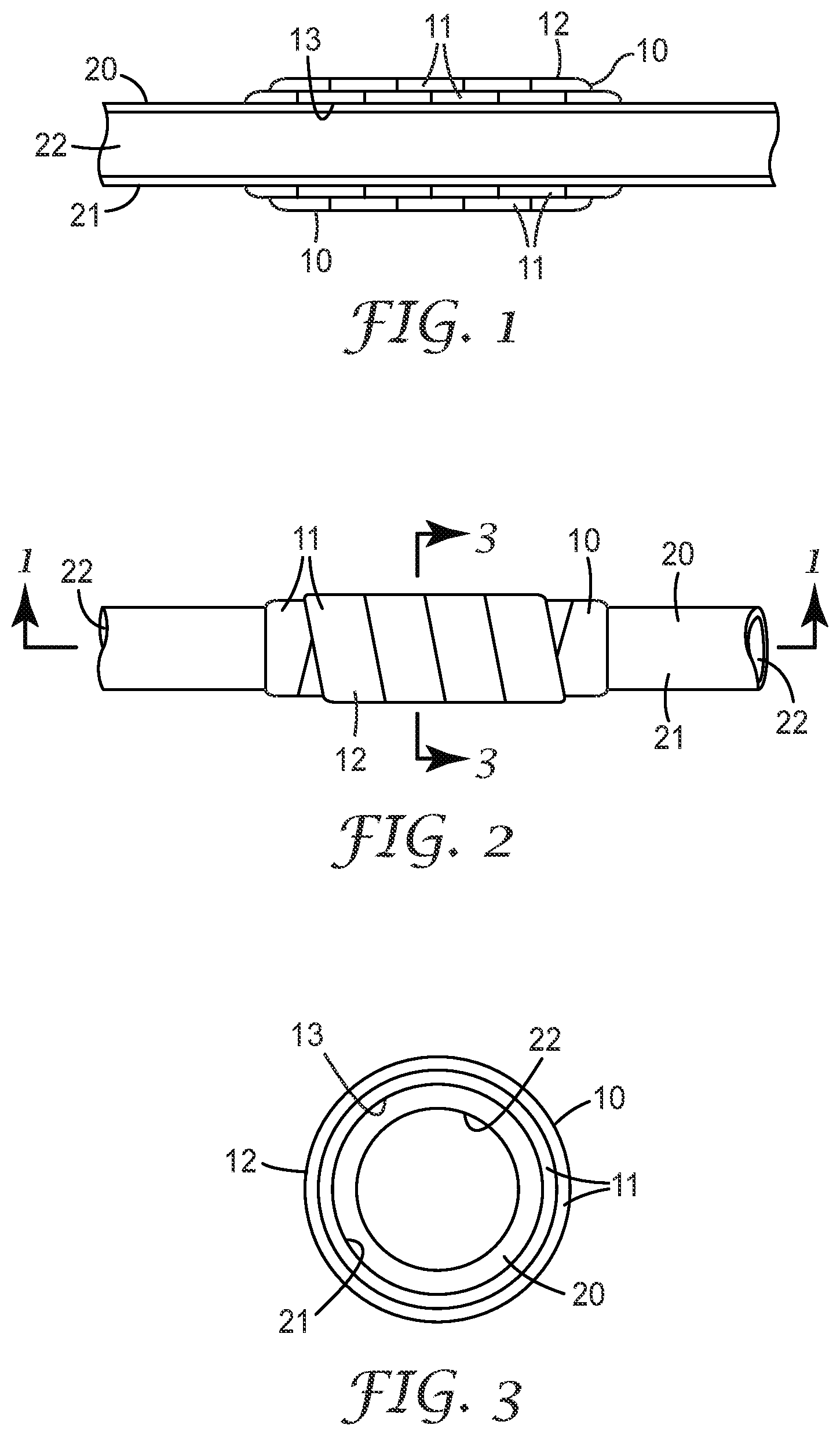
This application is a continuation of U.S. application Ser. No. 16/513,833, filed Jul. 17, 2019, now allowed, which is a continuation of U.S. application Ser. No. 14/345,535, filed Mar. 18, 2014, now granted as U.S. Pat. No. 10,450,936, which is a national stage filing under 35 U.S.C. 371 of PCT/US2012/056543, filed Sep. 21, 2012, which claims priority to United States Provisional Application No. 61/537,600, filed Sep. 22, 2011, the disclosures of which are incorporated by reference in their entireties herein. The present invention relates to a thermal insulation, in particular to thermal insulation that can be suitable for exhaust systems, and more particularly to a thermal insulation wrap that can be suitable for use with an exhaust system component or other structure. Heat shields are known to be used in vehicles (e.g., automobiles) to insulate various parts of a vehicle exhaust system. However, heat shields are relatively expensive to make or purchase and expensive to install or replace when needed. There is a continuing need for better and more cost effective ways to insulate a vehicle exhaust system (e.g., an automobile exhaust system). The present invention can be used in an effort to provide a relatively low cost way to insulate a portion of a vehicle exhaust system (e.g., an automobile exhaust system) from other components (e.g., the vehicle interior) or areas (e.g., passenger compartment) of the vehicle, from areas adjacent (e.g., the ground underneath) the vehicle, from personnel performing maintenance on or being located near the vehicle exhaust system, from users riding the vehicle (e.g., a motorcycle or ATV), or any combination thereof. The present invention may also be used to maintain heat within the exhaust system allowing for the possibility of improved/lower emissions of products of combustion, In one aspect of the present invention, a component of an exhaust system for an internal combustion engine is provided. The component comprises a component structure having an interior through which exhaust gases flow; and a thermal insulating wrap for thermally insulating at least a portion of the component structure. The thermal insulating wrap comprises a fabric impregnated with a mixture of an inorganic binder, inorganic filler particles and water. The fabric comprises inorganic fibers and is impregnated with the mixture so as to form a pliable binder wrap. The pliable binder wrap is wound at least once around at least a portion of the component structure. It can be desirable for the thermal insulating wrap to further comprise at least one thermal insulator comprising inorganic fibers, where the thermal insulator is disposed between the pliable binder wrap and the exhaust system structure. In another aspect of the present invention, a thermal insulating wrap as described herein is provided separately from the exhaust system component structure. In a further aspect of the present invention, a kit is provided that comprises a thermal insulating wrap as described herein, where the pliable binder wrap is wound into the form of a roll and disposed into a container that forms a moisture barrier around the roll. If the thermal insulating wrap includes a thermal insulator, it can be desirable for the thermal insulator to be included outside of the container housing the pliable binder wrap. The kit may also include the fabric and mixture, used for making the pliable binder wrap, being kept separated (e.g., with the mixture being in a moisture barrier container) until the time for applying the pliable binder wrap. In another aspect of the present invention, a method is provided for making a thermal insulating wrap used with an exhaust system component, for an internal combustion engine. The method comprises: forming a mixture comprising mixing water, inorganic binder particles and inorganic filler particles (e.g., by mixing inorganic filler particles with a dispersion of inorganic binder particles); providing a fabric comprising inorganic fibers that can be wound at least once around at least a portion of a component structure of an exhaust system component; and impregnating the fabric with the mixture so as to form a pliable binder wrap. The fabric can be sized (e.g., die cut, laser cut, etc.) or otherwise dimensioned (e.g., manufactured with a desired configuration and desired dimensions) to facilitate the winding or wrapping of the fabric around the desired portion of an exhaust system component. It can be desirable for the method to also include the additional method feature of disposing at least one thermal insulator comprising inorganic fibers on one side of the pliable binder wrap such that, when the pliable binder wrap is wound completely around at least a portion of an exhaust system structure, the at least one thermal insulator is disposed between the pliable binder wrap and the exterior of the exhaust system structure. In an additional aspect of the present invention, an exhaust system of an internal combustion engine is provided that comprises a component according to the present invention. The present invention can also include an internal combustion engine in combination with the exhaust system. In another aspect of the present invention, a method is provided for thermally insulating a component of an exhaust system for an internal combustion engine, where the component comprises an exhaust system structure having an interior through which exhaust gases flow and an exterior. The method comprises providing a thermal insulating wrap suitable for thermally insulating at least a portion of the exterior of the exhaust system structure, where the thermal insulating wrap comprises an aqueous mixture comprising an inorganic binder and inorganic filler particles, and a fabric comprising inorganic fibers, with the fabric being impregnated with the aqueous mixture so as to form a pliable binder wrap. The method also comprises wrapping the pliable binder wrap so as to be wound completely around at least a portion of the exhaust system structure, and drying the pliable binder wrap so as to be transformed into a rigid binder wrap wound completely around at least the portion of the exhaust system structure. It can be desirable for the provided thermal insulating wrap to further comprise the feature of at least one thermal insulator comprising inorganic fibers, and for the at least one thermal insulator to be disposed between the pliable binder wrap and the exterior of the exhaust system structure during the wrapping of the pliable binder wrap around the exhaust system structure. In addition to other potential advantages, the present invention may provide one or any combination of the following advantages: a relatively low-cost approach to insulating all or a portion of an exhaust system of an internal combustion engine, especially relative to the cost of conventional heat shields; a thermal insulation that can be applied directly onto at least a portion of the exterior of an exhaust system structure; a thermal insulation system for an internal combustion engine exhaust system that can reduce an outer surface temperature of an automobile exhaust system structure to below 500° C., below 400° C., below 300° C., below 200° C., or even below 100° C.; a relatively simple method of insulating an exhaust system structure of an exhaust system of an internal combustion engine; elimination of heat shields and the associated heat shield rattle, heat shield tooling and heat shield attachment operations; cost effective way to replace the need for a thermally insulating double walled exhaust or other pipe; protects adjacent surroundings from excessive heat; keeps heat within selected portions of the exhaust system structure; a non-metallic thermal insulation system with a relatively reduced likelihood of corrosion, as compared to conventional heat shield systems; sound attenuation and thermal insulation; useful in repairing defects or damage in an exhaust system structure (e.g., holes in an exterior housing); sufficiently reduce the exterior temperature of a desired portion of an exhaust system structure to eliminate burning exposed skin coming in contact with that portion of the exhaust system structure (e.g., a motorcycle exhaust pipe); enhanced design freedom in configuring and locating the exhaust system structure; and sufficiently reduce the exterior temperature of an underneath portion of an exhaust system structure so as to prevent grass or brush fires caused by contact with the exhaust system structure (e.g., of off-road construction equipment). These and other aspects, features and/or advantages of the invention are further shown and described in the drawings and detailed description herein, where like reference numerals are used to represent similar parts. It is to be understood, however, that the drawings and description are for illustration purposes only and should not be read in a manner that would unduly limit the scope of this invention. The terms “comprises” and variations thereof do not have a limiting meaning where these terms appear in the description and claims. The words “preferred” and “preferably” refer to embodiments of the invention that may afford certain benefits, under certain circumstances. However, other embodiments may also be preferred, under the same or other circumstances. Furthermore, the recitation of one or more preferred embodiments does not imply that other embodiments are not useful, and is not intended to exclude other embodiments from the scope of the invention. As used herein, “a,” “an,” “the,” “at least one,” and “one or more” are used interchangeably. Thus, for example, the phrase “a thermal insulator” that can be used in the disclosed thermal insulating wraps can be interpreted to mean “one or more” thermal insulators. The term “and/or” means one or all of the listed elements or a combination of any two or more of the listed elements (e.g., preventing and/or treating an affliction means preventing, treating, or both treating and preventing further afflictions). As used herein, the term “or” is generally employed in its sense including “and/or” unless the content clearly dictates otherwise. Also herein, the recitations of numerical ranges by endpoints include all numbers subsumed within that range (e.g., 1 to 5 includes 1, 1.5, 2, 2.75, 3, 3.80, 4, 5, etc.). The above summary of the present invention is not intended to describe each disclosed embodiment or every implementation of the present invention. The description that follows more particularly exemplifies illustrative embodiments. In several places throughout the application, guidance is provided through lists of examples, which examples can be used in various combinations. In each instance, the recited list serves only as a representative group and should not be interpreted as an exclusive list. In the accompanying drawings: In describing preferred embodiments of the invention, specific terminology is used for the sake of clarity. The invention, however, is not intended to be limited to the specific terms so selected, and each term so selected includes all technical equivalents that operate similarly. As used in this specification and the appended claims, the singular forms “a”, “an”, and “the” encompass embodiments having plural referents, unless the content clearly dictates otherwise. As used in this specification and the appended claims, the term “or” is generally employed in its sense including “and/or” unless the content clearly dictates otherwise. In the practice of the present invention, an inventive feature is provided that comprises a thermal insulating wrap for thermally insulating at least a portion of a structure of an exhaust system component. The exhaust system component forms at least part of an exhaust system for an internal combustion engine such as, for example, that used in an aircraft, watercraft, land vehicle (e.g., an automobile, train, etc.), power generator, etc. In some embodiments, the thermal insulating wrap comprises (i) an aqueous mixture comprising an inorganic binder and inorganic filler particles; and (ii) a fabric comprising inorganic fibers. The fabric is impregnated with the aqueous mixture so as to form a pliable binder wrap that is dimensioned to be wound completely or at least mostly around at least a portion of the exhaust system structure (e.g., piping of the exhaust system structure). The pliable binder wrap is intended to be dried so as to be transformed into a rigid binder wrap that will remain in place so as to at least one of, or both, insulate and protect at least a portion of the exhaust system component. In other embodiments, the thermal insulating wrap comprises (i) the pliable binder wrap in combination with (ii) at least one thermal insulator comprising inorganic fibers, where the thermal insulator(s) is disposed between the pliable binder wrap and an exterior of the exhaust system structure (e.g., a length of an exhaust pipe). In other embodiments, the thermal insulating wrap comprises (i) the pliable binder wrap in combination with (ii) at least one thermal insulator comprising inorganic fibers, wherein the thermal insulator(s) is disposed between the pliable binder wrap and an exterior of an exhaust system structure (e.g., a length of an exhaust pipe), and (iii) an adhesive layer positioned between the thermal insulator(s) and the exterior of the exhaust system structure (e.g., an exhaust pipe) so as to enhance a bond between the thermal insulator(s) and the exterior. Pliable binder wrap 11 of thermal insulating wrap 10 can be in the form of a sheet or a strip that is wrapped or wound around the exterior of an exhaust system structure (e.g., outer pipe surface 21 of a length of exhaust pipe 20). When in the form of a sheet, pliable binder wrap 11 can have a width that is comparable to that of the portion of the exterior of the exhaust system structure to be thermally insulated. That is, when pliable binder wrap 11 is in the form of a sheet, it can be wide enough that all, most or at least a substantial portion of the exterior surface area of the exhaust system structure, which is to be thermally insulated, can be covered with only one winding (i.e., layer) of pliable binder wrap 11 around the exterior of the exhaust system structure. When pliable binder wrap 11 is in the form of a strip, the width of pliable binder wrap 11 is such that pliable binder wrap 11 must be wrapped or wound multiple times around the exterior of the exhaust system structure in order to cover all of the portion of the exterior of the exhaust system structure to be thermally insulated. Although not limited to any particular dimensions, typically pliable binder wrap 11 has an overall width ranging from about 1.0 centimeters (cm) to about 150 cm (more typically, an overall width ranging from about 5.0 cm to about 20.0 cm), and has an overall length of at least 25.0 cm (more typically, an overall length ranging from about 30.0 cm to about 6.0 meters (m)). Pliable binder wrap 11 comprises an aqueous mixture comprising an inorganic binder and inorganic filler particles. The inorganic binder can comprise a mixture of water and inorganic binder particles, where the particles are either in suspension, have been dissolved, or some of the particles are in suspension and some have been dissolved. The inorganic binder is preferably a solution of inorganic colloidal particles (e.g., a colloidal solution of silica or alumina particles). The inorganic binder may also be a sodium silicate, potassium silicate, or lithium silicate solution, where the sodium silicate and the potassium silicate are mostly or completely dissolved. Sodium silicate and potassium silicate can be in powder form, which can be dissolved in water to form the solution, and they can be already dissolved in a water solution. It has been discovered that the shelf life and strength of the pliable binder wrap can be improved by using a positively charged colloidal silica, sterically hindered colloidal silica, or de-ionized colloidal silica in the mixture, compared to some of the other more common negatively charged sodium or ammonium stabilized pliable binder wrap material choices. It is desirable for the inorganic filler particles to be particles of a clay such as, for example only, kaolin clay, bentonite clay, montmorillonite clay, or any combination thereof. The clay filler particles may also be in the form of a calcined clay, delaminated clay, water washed clay, surface treated clay, or any combination thereof. The inorganic filler particles may also be, alternatively or additionally, particles of elemental metal, metal alloy, precipitated silica, fume silica, ground silica, fumed alumina, alumina powder, talc, calcium carbonate, aluminum hydroxide, titanium dioxide, glass bubbles, silicon carbide, glass frit, calcium silicate, or any combination thereof. The inorganic filler particles may be any other fine particulate that completely, mostly or at least substantially retains the inorganic binder in the fabric without forming the mixture into a gel or otherwise coagulating, when mixed with the inorganic binder (especially inorganic colloidal binder particles) in the presence of water, such that the wrap becomes a solid mass that cannot be wound, or is at least very difficult to wind, around the exterior of the exhaust system structure. It can be desirable for the inorganic filler particles to have a maximum size (i.e., major dimension) of up to about 100 microns, 90 microns, 80 microns, 70 microns, 60 microns or, preferably, up to about 50 microns. In some embodiments, it may be desirable for the aqueous mixture to further comprise dyes, pigment particles, IR reflecting pigment particles, biocides, thickening agents, pH modifiers, PH buffers etc. The fabric for forming a pliable binder wrap (e.g., pliable binder wrap 11) comprises a fabric comprising inorganic fibers (e.g., continuous glass fibers, silica fibers, basalt fibers, polycrystalline fibers, heat treated refractory ceramic fibers or any combination thereof,) suitable for being one or any combination of non-woven, woven, and/or knitted into a fabric. As used herein, a fabric refers to a non-woven fabric, woven fabric, knitted fabric or a combination of these types of fabric. Only non-woven fabrics with sufficient structural integrity are useful in the present invention. For example, it is important that a fabric according to the present invention exhibit sufficient strength (e.g., tensile strength) to survive being wound around the applicable exhaust system structure without tearing apart. A fabric according to the present invention can be made from the same or different types of fibers. As discussed herein, the fabric of the pliable binder wrap is saturated, soaked, coated, sprayed or otherwise impregnated throughout all, most or at least substantial portion of its thickness with the aqueous mixture so as to form a wet and pliable binder wrap (e.g., pliable binder wrap 11). The fabric can be impregnated with the aqueous mixture before or after being applied to the exterior of the exhaust system structure. The pliable binder wrap can then be dried so as to form a rigid binder wrap of a resulting thermal insulating wrap (e.g., thermal insulating wrap 10). As used herein, the term “dried” refers to the pliable binder wrap being heated to a temperature that is hot enough and for a time that is long enough to cause the pliable binder wrap (i.e., the aqueous mixture) to harden and become a rigid binder wrap (i.e., a rigid mixture). The aqueous mixture used to impregnate the fabric of exemplary thermal insulating wrap 10 is typically a slurry comprising water, an inorganic binder and inorganic filler particles. Although the weight percent of each component within the slurry may vary, typically a given slurry comprises from about 20.0 to about 54.0 percent by weight (pbw) of water, from about 1.0 to about 36.0 pbw of one or more inorganic binders, and from about 10.0 to about 70.0 pbw of inorganic filler particles, based on a total weight of the slurry. More typically, a given slurry comprises from about 22.0 to about 45.0 pbw of water, from about 5.0 to about 30.0 pbw of one or more inorganic binders, and from about 20.0 to about 55.0 pbw of inorganic filler particles, based on a total weight of the slurry. Although the particle size of the inorganic binder material is not limited, typically, the inorganic binder comprises inorganic binder particles having a maximum particle size of about 200 nm, preferably a maximum particle size of about 100 nm. More typically, the inorganic binder comprises inorganic binder particles having a particle size ranging from about 1.0 to about 100 nm. Even more typically, the inorganic binder comprises inorganic binder particles having a particle size ranging from about 4.0 to about 60 nm. Further, although the particle size of the inorganic filler particles is not limited, typically, the inorganic filler particles have a maximum particle size of about 100 microns (μall). More typically, the inorganic filler particles have a particle size ranging from about 0.1 μm to about 100 μm. Even more typically, the inorganic filler particles have a particle size ranging from about 0.2 μm to about 50 μm. Although exemplary thermal insulator 30 is shown as a single thermal insulator in In embodiments using a plurality of separate thermal insulators positioned between the pliable binder wrap (e.g., exemplary pliable binder wrap 11) and the exterior surface of the exhaust system structure (e.g., outer pipe surface 21 of exhaust pipe 20), the thermal insulators may be (i) spaced apart and separated from one another so as to form gaps between adjacent thermal insulators (e.g., as shown in When one or more thermal insulators are used in a given thermal insulating wrap (e.g., thermal insulating wrap 10), the thermal insulating wrap comprises at least one or a plurality of thermal insulators comprising inorganic fibers. The insulator(s) may be dimensioned so as to insulate all or any desired portion of the exterior of the exhaust system structure (e.g., exterior surface 21 of pipe 20). The thermal insulator also, or alternatively, can function to reduce the likelihood of the rigid fabric wrap (i.e., dried pliable binder wrap 11) cracking or fracturing due to thermal expansion of the exhaust system component. That is, the insulator can absorb the expansion of the exhaust system component. As shown in The insulator can be dimensioned so as to be disposed over all, most, or a desired portion of the area of the exterior surface of the exhaust system structure (e.g., exterior surface 21 of pipe 20). Preferably, the pliable binder wrap, in whatever form, is wound so that no portion of the thermal insulator(s) is exposed. Insulators suitable for use in the present invention can be in the form of a woven or nonwoven fibrous web, mat, scrim or strip. The insulator can include one or more layers and comprise any suitable commercially available ceramic fiber insulation. Without intending to be so limited, such insulators may comprise, for example, glass fibers, silica fibers, basalt fibers, refractory ceramic fibers, heat treated refractory ceramic fibers, polycrystalline fibers, high temperature biosoluble inorganic fibers, carbon fibers, or graphite fibers, or aerogel based insulators, etc., or any combination thereof, as desired. Intumescent materials (e.g., vermiculite, graphite, etc.) may also be included to provide compression, if needed to prevent movement. The thermal insulator may comprise intumescent materials and non-intumescent materials. The thermal insulator may be intumescent or non-intumescent. The thermal insulator may also comprise or be used with materials suitable for functioning as a fire stop. For example, a relatively thinner single or multiple layer fire stop material could form a laminate with a relatively thicker single or multiple layer non-intumescent thermal insulator, where the thermal insulator is sufficiently compliant and thick enough to accommodate heat induced expansion of the fire stop material (e.g., an intumescent material) with heat. With this embodiment, the thermal insulator would be compliant (i.e., compressible) enough to allow for the expansion of the fire stop material. In such a compressed state, the insulating properties of the thermal insulator would likely be as good as they would be when the thermal insulator is in its uncompressed condition. It is the temperature that the pliable binder wrap is exposed to, rather than the temperature of the system component structure, that will determine the choice of materials used for the pliable binder wrap (e.g., the fabric, inorganic binders and inorganic filler particles). For example, if the system component structure (e.g., an exhaust system component structure) exhibited an exterior surface temperature of 1000° C., the materials used for the pliable binder wrap may not need to survive such an elevated temperature, if a thermal insulator is used that effectively insulates the pliable binder wrap materials from the elevated temperature of the system component structure. In fact, by employing one or more such thermal insulators, it may be possible to use organic materials (e.g., any combination of organic fibers, an organic fiber fabric, organic binder, and organic filler particles) to make part or all of the pliable binder wrap. It may also be desirable to use such organic materials to make part of the pliable binder wrap, even without using such a thermal insulator. By comprising an appropriate fibrous material, the thermal insulator may also exhibit acoustical properties or achieve other acoustical benefits. In other embodiments of the present invention, an optional adhesive layer (not shown) may be used to enhance the bond between (i) a given pliable binder wrap (e.g., exemplary pliable binder wrap 11) and/or a given thermal insulator (e.g., exemplary thermal insulator 30) and (ii) an exterior surface of the exhaust system structure (e.g., outer pipe surface 21 of exhaust pipe 20). High-temperature adhesive may comprise a heat-resistant, dryable adhesive comprising a mixture of colloidal silica and clay, or a mixture of sodium or potassium silicate and clay. The adhesive may also contain delaminated vermiculite, fumed silica, fumed alumina, titanium dioxide, talc, or other finely ground metal oxide powders. The adhesive may further comprise one or more organic binders. Suitable organic binders include, but are not limited to, ethylene vinyl acetate (EVA), acrylic, urethane, silicone elastomers and/or silicone resins. One or more organic binders may be added to improve green strength or enhance water resistance of the adhesive. The dryable adhesive may also contain IR reflective pigments, glass or ceramic bubbles or micro-porous materials such as aerogels. High-temperature adhesive may be applied directly onto outer pipe surface 21 of exhaust pipe 20 or a thermal insulator (e.g., exemplary thermal insulator 30), which is subsequently applied over outer pipe surface 21 of exhaust pipe 20. The present invention is further directed to kits comprising one or more of the elements mentioned herein. In some embodiments, for example, the kit comprises one or more of the following elements: (i) one or more pliable binder wraps (e.g., one or more pliable binder wraps 11), desirably, wound into the form of a roll and stored within a moisture barrier container; (ii) one or more thermal insulators; (iii) one or more units/sheets of adhesive either separate from or attached to an outer surface of element (i) and/or element (ii); and (iv) a cutting device (e.g., a razor or scissors). In an alternative kit embodiment, the mixture and the fabric used in making the pliable binder wrap are kept separated and combined later (e.g., before or after the fabric is applied to the component structure. Other exemplary exhaust system components that can benefit from the present invention can include, for example, pollution control devices (e.g., diesel particulate filters or traps, catalytic converters, etc.), mufflers, expansion chambers, and resonators. Referring to To address this problem, a separate piece of an inorganic fibrous mat or other structure 68 can be disposed around the port 64, for example, by forming an opening (e.g., a slit or hole) through the mat 68 that is configured to receive the port 64 therethrough. In this way, the mat 68 can be positioned around the port 64 and against the exterior surface of the catalytic converter main housing 61, e.g., in the manner shown in It is desirable for the fibrous mat 68 to be impregnated with an aqueous mixture, like that used to make the pliable binder wrap 63, so as to form a pliable binder mat 68 with properties, when dried, that are similar or identical to the pliable binder wrap 63, when it is dried (i.e., the rigid binder wrap 63). Thus, when the pliable binder mat 68 is in a dried state, it transforms into a rigid binder mat 68, and the exposed portions of the rigid binder mat 68 (e.g., in open areas 66) will exhibit properties at least similar to, or identical to, those of the rigid binder wrap 63. As used herein, the term “dried” also refers to the pliable binder mat being heated to a temperature that is hot enough and for a time that is long enough to cause the pliable binder mat (i.e., the aqueous mixture) to harden and become a rigid binder mat (i.e., a rigid mixture). The following Examples have been selected merely to further illustrate features, advantages, and other details of the invention. It is to be expressly understood, however, that while the Examples serve this purpose, the particular ingredients and amounts used as well as other conditions and details are not to be construed in a manner that would unduly limit the scope of this invention. The following is a description of the process used to test the crush strength of a rigid binder wrap according to the present invention. All samples were produced using four foot lengths of two inch wide fiberglass knit tape, like that described in the Example of U.S. Pat. No. 4,609,578, which patent is incorporated herein by reference in its entirety. The sample pliable binder wraps were made by dipping the fabric tape into each specified slurry mixture followed by hand massaging the slurry into the fabric to evenly saturate the slurry into the fabric. At room temperature, each sample of the four foot length two inch wide pliable binder wrap was wrapped around a 2″ diameter cylindrical aluminum mandrel (i.e., with a 2 mil polyester film wrapped around the mandrel to make removal easier) using one kg of winding force to form hollow cylinders two inches long with a two inch inside diameter, an average outside diameter of from about 2.2 to 2.4 inch, and an average wall thickness of about 0.1 to 0.2 inch. Each sample of the resulting pliable hollow cylinders was dried at 90° C. for at least one hour while still on the mandrel. After being dried, each of the resulting hard cylinders was removed from the mandrel. Some of the hard cylinders were cooled then placed in a MTS force measurement device to evaluate their individual crush strength. The force measurement device compresses the cylinder at a rate of one inch per minute while recording resultant force. The peak force is recorded. Each sample was positioned in the force measurement device with the opening of the test cylinder lying horizontal. Other samples of the hard cylinders subjected to additional conditioning being tested for crush strength. In particular, some of the hard cylinder samples were heated to 500° C. for 18 hours, allowed to cool to room temperature, and then tested for crush strength. Other hard cylinder samples were heated to 500° C. for 18 hours, allowed to cool to room temperature, soaked in water for 18 hrs, and then tested for crush strength. The following materials as shown in Table 1 were used in the examples below: Embodiments of the invention were produced by the method generally described herein. Slurries were prepared using ingredients shown above. In each slurry, inorganic materials were added to liquid component(s) using a high shear mixer and blended until smooth to form a given slurry as shown in Table 2 below. Each knitted fiberglass fabric tape was impregnated with a given slurry to produce a given pliable thermal insulating wrap sample, and subsequently dried via a drying/heat treatment procedure as shown in Table 3 below. In each test sample, a given slurry was coated onto ECG heat-set 2″ wide knit with a weight of 20 grams (g) and a length of 4 feet. Each sample was subsequently tested for crush strength as described above. Results are shown in Table 3. Additional test samples were prepared using the procedures of Example 1. The following test samples utilized various colloidal binders. Results are shown in Table 4. Additional test samples were prepared using the procedures of Example 1. The following test samples utilized sodium silicate binders. Results are shown in Table 5. Additional test samples were prepared using the procedures of Example 1. The following test samples show crush strength as filler weight percent varies in a given test sample. Results are shown in Table 6. Additional test samples were prepared using the procedures of Example 1. The following test samples show crush strength as slurry coating weight varies in a given test sample. Results are shown in Table 7. Additional test samples were prepared using the procedures of Example 1 except various fabrics and fabric weights were utilized as shown in Table 8 below. Results are shown in Table 8. Additional test samples were prepared using the procedures of Example 1 except colloidal oxides or sodium silicates were not utilized. Results are shown in Table 9. Samples 604, 605, and 606 utilize in situ formations of silicate via dissolution of clay by sodium hydroxide to form silicates. System Component Embodiments
at least one mixture (e.g., an aqueous mixture) comprising an inorganic binder, inorganic filler particles, and water and/or other suitable solvent(s); a fabric comprising inorganic fibers, the fabric being impregnated with the mixture so as to form a pliable binder wrap, wherein the pliable binder wrap is wound two or more (multiple) times around, at least once (i.e., at least one complete revolution) around, or almost completely (i.e., more than 180°, 190°, 200°, 210°, 220°, 230°, 240°, 250°, 260°, 270°, 280°, 290°, or 300° and less than)360° around at least a portion of the system component structure. The filler particles allow for a very high solids content of the binder/filler mixture to remain in the fabric after the water and/or other solvent(s) evaporate or are otherwise removed. Examples of such a system that exhibits or produces such an elevated temperature include an exhaust system for an internal combustion engine, as well as industrial applications such as insulating steam lines or other high temperature lines. Examples of such systems susceptible to being damaged by exposure to elevated temperatures (e.g., such as caused by a fire or other high temperature environments) include commercial or industrial systems, like those found in buildings, and residential systems, like those found in homes. Such systems may include, e.g., fittings, fuel lines, electric lines, hydraulic lines, pneumatic lines, etc. that can be found in buildings and that need to be protected from excessive heat such as, for example, from a fire. For an exhaust system, the component structure can be an exhaust system structure (e.g., an exhaust pipe, pollution control device, muffler, expansion chamber, resonator etc.) having an interior through which exhaust gases flow, and the thermal insulating wrap is intended to thermally insulate so as to keep heat within at least a portion, most or all of the exhaust system structure. For an electrical system, the component structure could be, for example, an electrical conduit, pipe or circuit box through which electrical wires are run, and the thermal insulating wrap is intended to thermally insulate so as to keep heat out of at least a portion, most or all of the electrical system component structure.
7. The component according to any one of embodiments 1 to 6, wherein the inorganic binder comprises a mixture of water and inorganic binder particles.
17. The component according to any one of embodiments 1 to 16, wherein the inorganic filler particles comprise particles of a calcined clay, delaminated clay, water washed clay, surface treated clay, or any combination thereof.
It is desired that the rigid binder wrap be at most crushable, while the overall integrity of the rigid binder wrap is preserved. As used herein, the overall integrity of the rigid binder wrap is considered to be preserved as long as the underlying thermal insulator (when present), or the underlying exterior surface of the system component structure (i.e., the underlying surface not covered by a thermal insulator) would not be substantially exposed such that the rigid binder wrap could no longer perform its intended purpose (e.g., protecting the underlying structure, providing the desired degree of insulation, etc.). The purpose of the rigid binder wrap can include at least one or any combination of providing a degree of thermal insulation, as well as protecting the thermal insulator, the system component structure, or both from being damaged (e.g., by any one or any combination of road debris impacts, wind, vibrational forces, inclement weather, etc.). Thus, it can be acceptable for the rigid binder wrap to be in some degree of a crushed state. It is desirable, however, for the rigid binder wrap not to shatter into pieces that fall off of the system component structure and are large enough to prevent the rigid binder wrap from performing its intended purpose.
Thermal Insulating Wrap Embodiments
a mixture comprising an inorganic binder, inorganic filler particles, and water and/or other suitable solvent(s); and a fabric comprising inorganic fibers, the fabric being impregnated with the mixture so as to form a pliable binder wrap, wherein the pliable binder wrap is dimensioned to be wound two or more (multiple) times around, at least once (i.e., at least one complete revolution) around, or almost completely (i.e., more than 180°, 190°, 200°, 210°, 220°, 230°, 240°, 250°, 260°, 270°, 280°, 290°, or 300°and less than)360°around at least a portion of the system component structure.
at least one thermal insulator comprising inorganic fibers, wherein the at least one thermal insulator is disposed such that, when the thermal insulating wrap is applied, the at least one thermal insulator is disposed between the pliable binder wrap and a system component structure (e.g., the exterior of an exhaust system component structure). Kit Embodiment
Method of Making Thermal Insulating Wrap Embodiments
forming a mixture comprising mixing water and/or other suitable solvent(s), inorganic binder particles and inorganic filler particles; providing a fabric comprising inorganic fibers that can be wound two or more (multiple) times around, at least once (i.e., at least one complete revolution) around, or almost completely (i.e., more than 180°, 190°, 200°, 210°, 220°, 230°, 240°, 250°, 260°, 270°, 280°, 290°, or 300° and less than)360° around at least a portion of a system component structure (e.g., an exhaust system component structure); and impregnating the fabric with the mixture so as to form a pliable binder wrap, wherein the fabric can be impregnated with the mixture before or after being wound around the system component structure.
disposing at least one thermal insulator comprising inorganic fibers such that, when the pliable binder wrap is wound around at least a portion of a system component structure, the at least one thermal insulator is disposed between the pliable binder wrap and the system component structure. System Embodiment
Internal Combustion Engine Embodiment
Method of Thermally Insulating Embodiments
providing a thermal insulating wrap suitable (e.g., dimensioned and/or designed) for thermally insulating at least a portion of the system component structure (e.g., the exterior of the exhaust system component structure), with the thermal insulating wrap comprising: a mixture comprising an inorganic binder, inorganic filler particles, and water and/or other suitable solvent(s), and a fabric comprising inorganic fibers, with the fabric being impregnated with the mixture so as to form a pliable binder wrap; wrapping the pliable binder wrap so as to be wound two or more (multiple) times around, at least once (i.e., at least one complete revolution) around, or almost completely (i.e., more than 180°, 190°, 200°, 210°, 220°, 230°, 240°, 250°, 260°, 270°, 280°, 290°, or 300° and less than)360° around at least a portion of the system component structure; and drying the pliable binder wrap so as to be transformed into a rigid binder wrap wound around at least the portion of the system component structure.
This invention may take on various modifications, alterations and uses without departing from its spirit and scope. For example, the present invention may be useful in repairing a system component structure or in covering and/or protecting a previously repaired portion of a system component structure. In particular, for example, the present inventive wrap may be useful in closing a hole or otherwise repairing a pipe or housing such as, e.g., an exhaust pipe or the housing of a pollution control device (e.g., a diesel particulate filter or trap, a catalytic converter, etc.), muffler, expansion chamber, resonator, or other system component structure. The present inventive wrap may also be useful in securing, e.g., a plate or foil (e.g., made of metal or ceramic) or other repair structure so as to close over or otherwise repair such a hole or defect in a system component structure (e.g., an exhaust system component structure). Accordingly, this invention is not limited to the above-described but is to be controlled by the limitations set forth in the following claims and any equivalents thereof. This invention may be suitably practiced in the absence of any element not specifically disclosed herein. All patents and patent applications cited above, including those in the Background section, are incorporated by reference into this document in total. A component of an exhaust system for an internal combustion engine. The component comprises an exhaust system structure having an interior through which exhaust gases flow and an exterior, and a thermal insulating wrap for thermally insulating at least a portion of the exterior of the exhaust system structure. The thermal insulating wrap comprises an aqueous mixture comprising an inorganic binder and inorganic filler particles, and a fabric comprising inorganic fibers. The fabric is impregnated with the aqueous mixture so as to form a pliable binder wrap. The pliable binder wrap is wound completely around at least a portion of the exhaust system structure. It can be desirable for the component to further comprise at least one thermal insulator comprising inorganic fibers, where the thermal insulator is disposed between the pliable binder wrap and the exterior of the exhaust system structure. 1. A component of a system, where (a) a portion or all of the component exhibits or produces an external elevated temperature and the system needs to be thermally insulated to prevent or reduce the loss or transfer of heat from the component into the surrounding environment, (b) a portion or all of the component or something within the component is susceptible to being damaged by exposure to elevated temperatures, or (c) both (a) and (b), said component comprising a system component structure; and a thermal insulating structure for thermally insulating at least a portion of said system component structure, with said thermal insulating structure comprising:
a mixture comprising an inorganic binder, inorganic filler particles, and water; and a woven fabric comprising inorganic fibers in the form of a sheet- or mat-like structure, said woven fabric being impregnated with said mixture so as to form a pliable binder structure, wherein said pliable binder structure is positioned on at least a portion of said system component structure such that said pliable binder structure forms an exposed surface of said system component structure. 2. The component according to 3. The component according to 4. The component according to 5. The component according to 6. The component according to 7. The component according to 8. The component according to 9. The component according to 10. The component according to 11. The component according to 12. A thermal insulating structure for thermally insulating at least a portion of a system component structure, with said thermal insulating structure comprising:
a mixture comprising an inorganic binder, inorganic filler particles, and water; and a woven fabric comprising inorganic fibers in the form of a sheet- or mat-like structure, said woven fabric being impregnated with said mixture so as to form a pliable binder structure, wherein said pliable binder structure is dimensioned to be wound almost completely or at least once around at least a portion of the system component structure, and said inorganic filler particles comprise any particulate, when mixed with said inorganic binder in the presence of water, that causes a substantial portion of said inorganic binder to be retained in said woven fabric without forming a gel or otherwise coagulating such that said pliable binder structure becomes a solid mass before said pliable binder structure can be wound almost completely or at least once around said system component structure. 13. The thermal insulating structure of 14. The thermal insulating structure of 15. The thermal insulating structure of 16. A thermal insulating structure for thermally insulating at least a portion of a system component structure, with said thermal insulating structure comprising:
a mixture comprising an inorganic binder, inorganic filler particles, and water; a woven fabric comprising inorganic fibers in the form of a sheet- or mat-like structure, said woven fabric being impregnated with said mixture so as to form a pliable binder structure; and at least one thermal insulator comprising inorganic fibers, wherein said pliable binder structure is dimensioned to cover almost completely or all of the system component structure, and wherein said at least one thermal insulator is disposed such that, when said thermal insulating structure is applied, said at least one thermal insulator is disposed between said pliable binder structure and the system component structure. 17. The thermal insulating structure of 18. The component of 19. The component of 20. The component of CROSS REFERENCE TO RELATED APPLICATIONS
BACKGROUND
SUMMARY OF THE INVENTION
BRIEF DESCRIPTION OF THE DRAWINGS
DETAILED DESCRIPTION OF CERTAIN EMBODIMENTS
Test Methods
Crush Strength Test
EXAMPLES
Fabrics Description Source ECG heat set knit 2″ 3″ or 4″ wide 3M, St. Paul MN SCOTCHCAST ™ knit heat treated G yarn ECG non-heat 3″ wide 3M, St. Paul MN set knit SCOTCHCAST ™ knit not heat treated G yarn ECDE heat 4″ wide 3M, St. Paul MN set knit SCOTCHCAST ™ knit heat treated DE yarn silica weave TECSIL ® 3″ 13-621 Intec, Anaheim CA e-glass weave #8817K68 McMaster-Carr, Chicago IL Inorganic Binder Description Source colloidal silica 4 nm NALCO ™ 1115 Nalco, Chicago IL colloidal silica 15 nm NALCO ™ 1144 Nalco, Chicago IL colloidal silica 20 nm NALCO ™ 2327 Nalco, Chicago IL colloidal silica 60 nm NALCO ™ 1060 Nalco, Chicago IL colloidal alumina NYACOL ™ AL20 Nyacol, Ashland 50 nm MA colloidal silica 8 nm LUDOX ® SM Grace Davidson Columbia MD Colloidal silica Ludox CL-P Grace Davidson positively charged Columbia MD Colloidal silica Ludox TMA Grace Davidson deionized Columbia MD Colloidal silica 20 nm NALCO 1056 Nalco, Chicago, IL positive charge Colloidal silica Bindzil cc401 AkzoNobel, Marietta, sterically stabilized GA Colloidal silica Bindzil CAT80 AkzoNobel, Marietta, positive charge GA wide particle size range Colloidal silica Bindzil DP5100 AkzoNobel, Marietta, neutral pH GA sodium silicate STIXO ™ NN PQ Corporation, Valley Forge PA Inorganic Fillers and Additives Description Source kaolin clay POLYPLATE ™ P KaMin, Macon GA calcined kaolin 2000C KaMin, Macon GA bentonite clay BENTOLITE ® Southern Clay Gonzales TX aluminum Huber ONYX Huber, Norcross GA hydroxide 1 ELITE ® aluminum MARTINAL ® Albemarle, Baton hydroxide 2 OL-104 LE Rouge LA fumed silica CAB-O-SIL ® M-5 Cabot, Boston MA fumed alumina SpectrAl ® grade 51 Cabot, Boston MA alumina powder Type A Fisher Scientific, Fairlawn NJ precipitated silica ZEOTHIX ® 265 Huber, Norcross, GA ground silica 1 MIN-U-SIL ™ 10 U.S. Silica, Frederick MD ground silica 2 MIN-U-SIL ™ 30 U.S. Silica, Frederick MD aluminum powder 325 mesh #11067 Alfa/Aesar, Ward Hill MA talc talc powder J.T. Baker, Phillipsburg NJ aluminum silicate #14231 Alfa/Aesar, Ward Hill MA calcium silicate MICRO-CEL ® Celiter Corp., Lompoc CA calcium carbonate Sigma Aldrich, St. Louis MO silicon carbide 800W Electro Abrasives, Buffalo NY glass bubbles SCOTCHLITE ™ K37 3M, St. Paul MN glass frit EG02934VEG Ferro, Cleveland OH titanium dioxide R900 Dupont, Wilmington DE sodium hydroxide Pellets EMD, Germany nitric acid 69% Nitric acid J.T. Baker, Phillipsburg NJ Kaolin clay Dixie clay R.T. Vanderbuilt, Norwalk, CT Wollastonite Vansil 50 R.T. Vanderbuilt, Norwalk, CT Manganese Ferrite FM-2400 Rockwood, Beltsville, MD Silane Z-6040 Dow-Corning, Midland MI Example 1
Slurries Slurry Composition 1 50 wt % 2327 colloidal silica, 50 wt % POLYPLATE ™ P 2 67 wt % 2327 colloidal silica, 33 wt % calcium carbonate 3 57.1 wt % 1144 colloidal silica, 42.9 wt % calcium carbonate 4 94.4 wt % 2327 colloidal silica, 5.6 wt % M-5 fumed silica 5 87.8 wt % 1144 colloidal silica, 12.2 wt % M-5 fumed silica 6 60 wt % 2327 colloidal silica, 40 wt % talc 7 52.9 wt % 1144 colloidal silica, 47.1 wt % talc 8 60 wt % 2327 colloidal silica, 40 wt % silicon carbide 9 50 wt % 2327 colloidal silica, 40 wt % aluminum powder, 10 wt % POLYPLATE ™ P 10 82.3 wt % 2327 colloidal silica, 17.7 wt % bentonite clay 11 84 wt % 2327 colloidal silica, 16 wt % fumed alumina 12 84.4 wt % 2327 colloidal silica, 15.6 wt % glass bubbles 13 50 wt % 2327 colloidal silica, 50 wt % titanium dioxide 14 66.7 wt % 2327 colloidal silica, 33.3 wt % alumina powder 15 84.2 wt % 2327 colloidal silica, 15.8 wt % precipitated silica 16 50 wt % 2327 colloidal silica, 50 wt % aluminum silicate 17 42.1 wt % 2327 colloidal silica, 57.9 wt % aluminum hydroxide-1 18 42.1 wt % 2326 colloidal silica, 57.9 wt % ground silica 1 19 42.1 wt % 2327 colloidal silica, 57.9 wt % ground silica 2 20 45.3 wt % 2327 colloidal silica, 50.0 wt % silica 1, 2.8 wt % silicon carbide, 1.8 wt % bentonite clay 21 60 wt % 2327 colloidal silica, 40 wt % POLYPLATE ™ P 22 60 wt % 2327 colloidal silica, 40 wt % 2000C calcined clay 23 44.5 wt % colloidal silica 1144, 33.3 wt % glass frit, 22.2 wt % 2000C 24 60 wt % SM colloidal silica, 40 wt % POLYPLATE ™ P 25 50 wt % 2327 colloidal silica, 50 wt % POLYPLATE ™ P 26 50 wt % 4 nm colloidal silica, 50 wt % POLYPLATE ™ P 27 50 wt % 60 nm colloidal silica, 50 wt % POLYPLATE ™ P 28 50 wt % 1144 colloidal silica, 50 wt % POLYPLATE ™ P 29 60 wt % colloidal alumina, 40 wt % POLYPLATE ™ P 30 100 wt % 2327 colloidal silica 31 100 wt % 4 nm colloidal silica 32 90 wt % 2327 colloidal silica, 10 wt % POLYPLATE ™ P 33 80 wt % 2327 colloidal silica, 20 wt % POLYPLATE ™ P 34 70 wt % 2327 colloidal silica, 30 wt % POLYPLATE ™ P 35 60 wt % 2327 colloidal silica 40 wt % POLYPLATE ™ P 36 100 wt % sodium silicate solution 37 80 wt % 2327 colloidal silica, 20 wt % 2000C 38 70 wt % 2327 colloidal silica, 30 wt % 2000C 39 60 wt % 2327 colloidal silica, 40 wt % 2000C 40 74.4 wt % sodium silicate, 18.6 wt % POLYPLATE ™ P, 7 wt % water 41 12.5 wt % sodium silicate, 50 wt % POLYPLATE ™ P, 37.5 wt % water 42 28.6 wt % sodium silicate, 42.8 wt % POLYPLATE ™ P, 28.6 wt % water 43 45 wt % 2327 colloidal silica, 50 wt % POLYPLATE ™ P, 5 wt % titanium dioxide 44 40 wt % sodium silicate, 30 wt % POLYPLATE ™ P, 30 wt % water 45 29.4 wt % sodium silicate, 35.3 wt % POLYPLATE ™ P, 35.3 wt % water 46 14.3 wt % sodium silicate, 42.8 wt % POLYPLATE ™ P, 42.8 wt % water 47 60 wt % POLYPLATE ™ P, 40 wt % water 48 69.5 wt % POLYPLATE ™ P, 30.5 wt % water 49 15 wt % 2327 colloidal silica, 55 wt % POLYPLATE ™ P, 30 wt % water 50 31 wt % 2327 colloidal silica, 49 wt % POLYPLATE ™ P, 20 wt % water 51 7.7 wt % sodium silicate, 46.2 wt % POLYPLATE ™ P, 46.2 wt % water 52 10 wt % sodium silicate, 90 wt % water 53 25 wt % sodium silicate, 75 wt % water 54 50 wt % sodium silicate, 50 wt % water 55 90.2 wt % 1144 colloidal silica, 9.8 wt % POLYPLATE ™ P 56 50 wt % 2327 colloidal silica, 33 wt % POLYPLATE ™ P, 17 wt % 2000C 57 55 wt % 2327 colloidal silica, 30 wt % POLYPLATE ™ P, 15 wt % 2000C 58 52.4 wt % 2327 colloidal silica, 31.7 wt % POLYPLATE ™ P, 15.8 wt % 2000C 59 7.9 wt % 4 nm colloidal silica, 68.3 wt % POLYPLATE ™ P, 23.7 wt % water 60 50 wt % 2327, 50 wt % aluminum hydroxide-2 61 44.5 wt % 1144 colloidal silica, 33.3 wt % glass frit, 22.2 wt % 2000C clay 62 53.3 wt % nitric acid treated 1144 colloidal silica*, 46.7 wt % POLYPLATE ™ P *Nitric acid added with stirring to 1144 colloidal silica until pH 2.3 is achieved. 63 83.7 wt % 1144 colloidal silica, 16.3 wt % calcium silicate 64 50% 1056 colloidal silica, 18% 2000C clay, 32% POLYPLATE ™ P 65 50% 1056 colloidal silica, 50% Dixie clay 66 50% 1144 colloidal silica, 50% Vansil 50 67 53% Cat 80 colloidal silica, 47% POLYPLATE P 68 50% cc401 colloidal silica, 45% POLYPLATE P, 5% FM2400 69 50% DP5110 colloidal silica, 45% POLYPLATE P, 5% FM2400 70 50% 1056 colloidal silica, 45% POLYPLATE P, 5% FM2400 71 53% cat 80 colloidal silica 42% Dixie clay, 5% FM2400 72 54% Ludox CL-P colloidal silica, 46% POLYPLATE P 73 50% Ludox TMA colloidal silica, 50% POLYPLATE P 74 25% 1056 colloidal silica, 25% Cat 80 colloidal silica, 25% Polyplate P, 25% Dixie clay 75 25% 1056 colloidal silica, 25% Cat 80 colloidal silica, 25% POLYPLATE P, 25% Dixie clay +0.33% Z-6040 silane Test Samples and Results Test Coated Dry weight Crush Sample Slurry weight (g) (g) Condition* strength N 1 60 74.9 58.4 90 157 2 60 60.9 48.6 500 93 3 2 82.0 57.1 90 69 4 2 89.1 61.3 500 116 5 3 110.2 79.3 90 174 6 3 112.5 80.8 500 242 7 3 108.5 78.2 500 wet 119 8 4 69.1 41.3 90 29 9 4 67.5 40.6 500 41 10 5 70.7 44 90 43.6 11 5 72.8 45 500 78 12 5 68.2 42.8 500 wet 58 13 6 73.4 54.2 90 85 14 6 66.6 49.8 500 52 15 6 68.4 51 500 wet 75 16 7 82.3 62.5 90 174 17 7 84.9 64.3 500 266 18 7 80.5 61.3 500 wet 199 19 8 79.4 58 90 60 20 8 77.8 57 500 116 21 8 83.9 60.9 500 wet 83 22 9 87.1 67 90 202 23 9 82.9 64 500 266 24 9 82.9 64 500 wet 233 25 10 67.6 44.1 90 52 26 10 65 42.8 500 100 27 11 66.8 43.2 90 25 28 11 65.6 42.6 500 38 29 12 67.6 43.5 90 42 30 12 67.6 43.5 500 43 31 12 66.6 43 500 wet 40 32 13 60.4 48.3 90 46 33 13 63.9 50.7 500 63 34 13 63.4 50.4 500 wet 66 35 14 84.1 58.4 90 205 36 14 83.2 57.9 500 164 37 14 84.7 58.8 500 wet 135 38 15 74.2 46.8 90 32 39 15 74.2 46.8 500 63 40 15 71.3 45.4 500 wet 46 41 16 67.7 53.4 90 98 42 16 69.4 54.6 500 209 43 16 67.7 53.4 500 wet 169 44 17 100 79.8 90 270 45 17 86.9 70 500 130 46 17 78.9 64 500 wet 117 47 18 96.7 77.3 90 257 48 18 93.6 75 500 297 49 18 97.3 77.8 500 wet 237 50 19 128.8 101.3 90 409 51 19 110.3 87.5 500 300 52 19 121.3 95.7 500 wet 335 53 20 93.6 73.4 90 307 54 20 90.7 71.3 500 417 55 20 90.7 71.3 500 wet 270 56 21 73.1 54 90 149 57 21 67.9 50.75 500 229 58 21 69.2 51.5 500 wet 178 59 22 74.7 55 90 187 60 22 76.7 56.3 500 216 61 22 75.9 55.8 500 wet 173 62 55 50.5 34 90 41 63 55 47.7 32.7 500 44 64 55 46.2 32 500 wet 37 65 56 88 67.6 90 153 66 56 70.3 55.2 500 219 67 56 75.3 58.7 500 wet 213 68 57 69.4 53.1 90 110 69 57 66.3 51 500 198 70 57 69.1 52.9 500 wet 165 71 58 75.6 58.1 90 124 72 58 78.2 59.9 500 271 73 58 77.8 59.6 500 wet 223 74 59 80.2 61.8 90 70 75 59 74.7 58 500 153 76 59 75 58.2 500 wet 129 77 43 65.6 53.3 90 93 78 43 57.4 47.3 500 140 79 43 63.6 51.8 500 wet 147 80 49 65.2 47.6 90 45 81 49 60.8 44.9 500 93 82 50 65 47.6 90 64 83 50 60.6 44.9 500 125 84 61 101.3 79.6 90 295 85 61 101.6 79.8 500 340 86 61 99.7 78.4 500 wet 329 87 63 84.1 53.9 90 175 88 63 85.1 54.9 500 200 89 63 81.4 53.6 500 wet 206 90 65 83.1 61 90 180 91 65 75.4 56 500 391 92 65 75.4 56 500 wet 344 93 66 88 68 90 425 94 66 90 69 500 519 95 66 88 68 500 wet 424 Condition* “90” means the sample was dried at 90° C. for two hours, cooled to room temperature, and then crushed. “500” means the sample was dried at 90° C. for two hours, then heated to 500° C. for 18 hours, cooled to room temperature, and then crushed. “500 wet” means the sample was dried at 90° C. for two hours, then heated to 500° C. for 18 hours, cooled to room temperature, then place in a water bath at room temperature for 18 hours, removed from water, and then crushed. Example 2
Test Samples and Results Test Coated Dry weight Crush Sample Slurry weight (g) (g) Condition strength N 100 25 74.3 58 90 161 101 25 71.6 56.1 500 307 102 25 69.4 54.6 500 wet 225 103 26 65 45.9 90 87 104 26 59.5 42.7 500 184 105 26 60.3 32.2 500 wet 154 106 27 65.6 54.2 90 136 107 27 60.8 50.6 500 270 108 27 61.7 51.3 500 Wet 212 109 28 75.6 58.9 90 217 110 28 74.3 58 500 420 111 28 71.6 56.1 500 wet 360 112 29 83.1 52.8 90 68 113 29 71.9 47 500 136 114 29 72.5 47.3 500 wet 91 115 24 71.7 50 90 173 116 24 69.1 48.5 500 260 117 24 70 49 500 wet 247 118 30 49 31.6 90 11 119 30 49.3 31.7 500 18 120 30 53 33.2 500 wet 18 121 31 53.3 30 90 13.5 122 62 87.7 66.4 90 96 123 62 80.5 61.8 500 187 124 62 80.8 62.3 500 wet 141 125 64 78.5 58 90 211 126 64 70.8 53 500 378 127 64 67.7 51 500 wet 331 128 67 78 60 90 198 129 67 72 56 500 468 130 67 73 57 500 wet 428 131 68 73 56 90 122 132 68 67 52 500 227 133 68 68 53 500 wet 177 134 69 75 56 90 112 135 69 65 49 500 211 136 69 66 50 500 wet 137 137 70 72 54 90 253 138 70 69 53 500 361 139 70 71 53 500 wet 370 140 71 76 59 90 265 141 71 71 55 500 495 142 71 68 53 500 wet 410 143 72 81 61 90 161 144 72 75 57 500 450 145 72 73 56 500 wet 377 146 73 71 54 90 91 147 73 72 55 500 202 148 73 64 49 500 wet 163 149 74 73 56 90 195 150 74 69 53 500 502 151 74 68 52 500 wet 378 152 75 69 54 500 489 153 75 66 51 500 460 Example 3
Test Samples and Results Test Coated Dry weight Crush Sample Slurry weight (g) (g) Condition strength N 200 36 80.2 43.6 90 208 201 40 93.9 55.3 90 313 202 41 81.9 54 90 202 203 41 83.7 54 500 242 204 41 85.6 56 500 wet 240 205 42 70.36 47.2 90 383 206 42 69.8 46.9 500 131 207 42 67.77 45.8 500 wet 150 208 44 54.8 35.9 90 257 209 44 61.4 38.9 500 90 210 44 63.1 39.7 500 wet 80 211 45 66.3 41.7 90 275 212 45 59.9 38.7 500 132 213 45 60.4 38.9 500 wet 94 214 46 68.1 43.9 90 145 215 46 60.3 39.5 500 175 216 46 59.7 39.2 500 wet 153 217 51 71.8 45.5 90 83 218 51 59.6 39.5 500 129 219 52 45.5 21 90 3 220 52 45.5 21 500 2 221 52 45.5 21 500 wet 2 222 53 47.6 22.7 90 13 223 53 44.5 22.4 500 12 224 53 45.51 22.5 500 wet 7 225 54 48.6 25.6 90 26 226 54 47 25.3 500 26 227 54 46.5 25.2 500 wet 26 Example 6
Test Samples and Results Test Coated Dry weight Crush Sample Slurry weight (g) (g) Condition strength N 300 32 58.5 37.7 90 37 301 33 55 38.2 90 46 302 34 66 46.7 90 99 303 35 79.5 58.1 90 166 304 1 69.6 54.7 90 193 305 37 67.3 44.6 90 105 306 38 71.4 49.8 90 109 307 39 94.5 67.7 90 229 Example 7
Test Samples and Results Test Coated Dry weight Crush Sample Slurry weight (g) (g) Condition* strength N 400 1 45.4 37.8 150 44 401 1 47.7 39.4 150 60 402 1 53.8 43.6 150 77 403 1 57.2 46 150 91 404 1 60.1 48 150 101 405 1 65.2 51.7 150 120 406 1 69.1 54.4 150 125 407 1 72 56.4 150 138 408 1 76.8 59.8 150 158 409 28 84.4 65.1 150 180 Condition* “150” means the sample was dried at 90° C. for 2 hours, then heated at 150° C. for 2 hours, cooled to room temperature, and tested. Example 8
Test Samples and Results Test Fabric Coated Dry Crush Sample Slurry Fabric weight (g) weight (g) weight (g) Condition Strength (N) 500 21 4″ ECG 37.9 144.8 106.3 90 302 501 21 4″ ECDE 39.4 153 112.1 90 338 502 21 3″ ECG 30.0 113.8 83.6 90 219 503 21 3″ ECG 33.1 110.3 82.53 90 270 no HT 504 21 Silica 71.0 222.1 167.7 90 575 505 21 E-glass 67.8 267 195.3 90 1628 weave Example 9
Test Samples and Results Coated Dry weight Crush Test Sample Slurry weight (g) (g) Condition strength N 600 47 57.8 42.7 90 34 601 48 85.3 65.4 90 52 602 48 79.1 61.1 500 154 603 48 78.6 60.7 500 wet 110 604 61 65.3 38.2 90 77 605 61 60.1 37.6 500 195 606 61 62.5 38 500 wet 170 Additional Embodiments