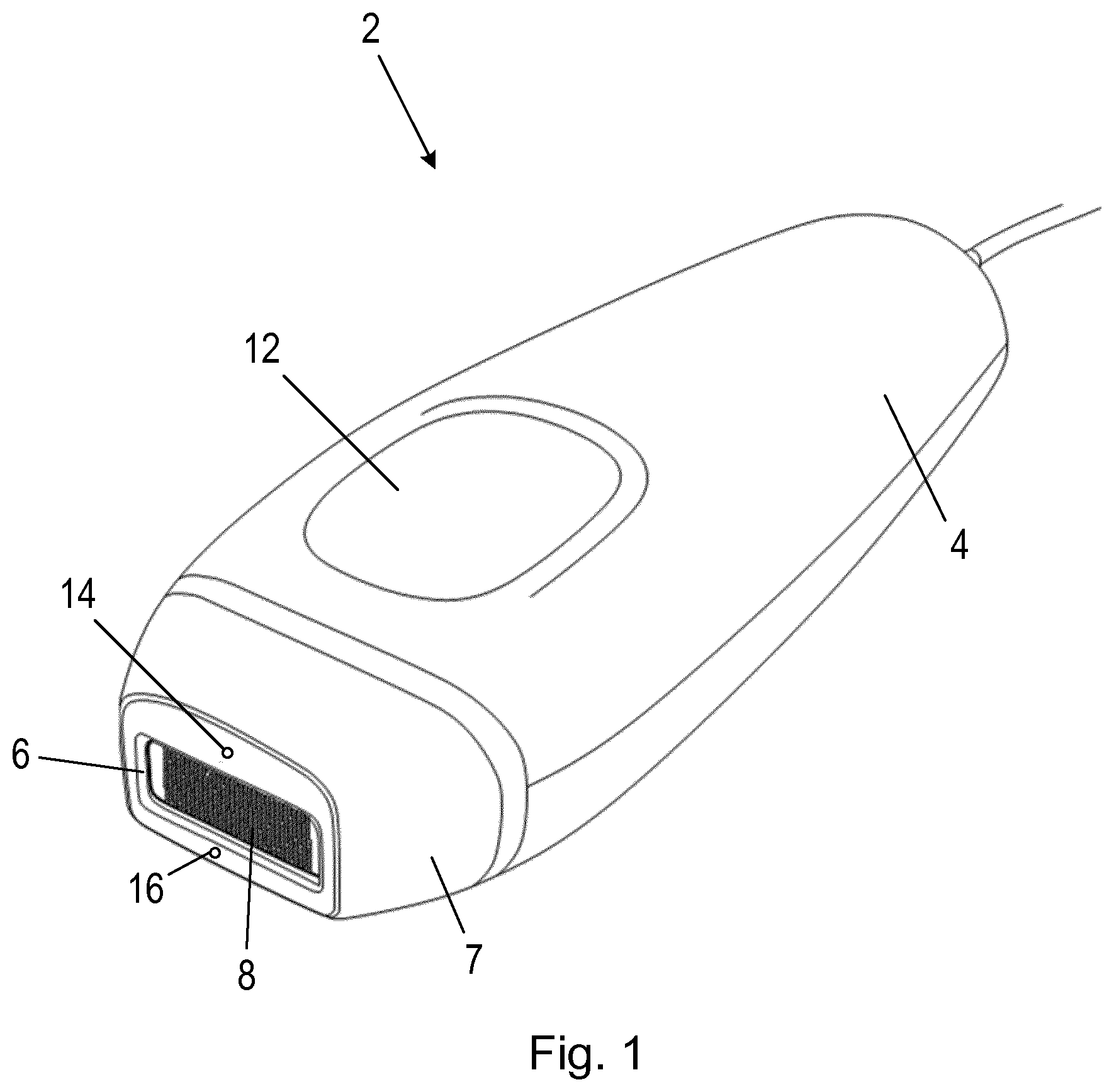
A HANDHELD DEVICE FOR PERFORMING A TREATMENT OPERATION ON SKIN
This disclosure relates to a handheld device for performing a treatment operation on skin of a subject, and in particular to a treatment operation in which energy pulses are applied to the skin. Techniques for removal of unwanted hairs include shaving, electrolysis, plucking, laser and light therapies (known as photoepilation) and injection of therapeutic anti-androgens. Light-based technologies are also used in other types of dermatological treatments, including hair growth reduction and treating acne. Through the use of an appropriate configuration of the light energy, i.e. in terms of wavelength, intensity and/or pulse duration, selective heating of the hair root and subsequent temporary or permanent damage to the hair follicle can be achieved. However, due to the high fluence required to achieve sufficient temperature elevation in the follicle, the energy consumption of devices that provide these energy pulses can be very high. This negatively affects the form factor, cost, treatment speed and overall attractiveness of a photoepilation-based device (particularly where the light energy is generated using light emitting diodes (LEDs)). Currently available devices require the user to position the device over an area of skin, trigger an energy pulse, manually move the device to another area of skin (e.g. a neighbouring area), trigger an energy pulse, and so on, until the user considers that the part of the body has been adequately treated. As a result of this, users of photoepilation devices face difficulties in efficiently and effectively using these devices over large areas of skin, for example the legs. The difficulties arise from the combination of a relatively large area of skin to be treated, a small device treatment window area, a lack of information on areas that have already been treated, inaccuracy in repositioning the device over a non-treated area with or without a sufficient overlap with a previously treated area (for example a slight overlap may be desirable for effective treatment using some types of photoepilation devices), and inherent limited patience of the user in ensuring full treatment coverage. These user-dependent issues result in high variability in compliance, treatment time and ultimately, treatment efficacy. In fact, based on an internal study, the measured treatment time of lower legs of 104 subjects varies from a minimum of 2:50 (minutes:seconds) to a maximum of 34:46 with a mean value of 13:49, with the recommended time of treatment for the lower leg being 8 minutes. It is an objective to provide devices for performing treatment operations on skin using energy pulses that can enable a user to complete the treatment operation in a more efficient and effective manner. For example, rather than having to reposition the device and then manually trigger an energy pulse, it is an objective to enable energy pulses to be delivered or applied to the skin while the device is moving over the skin, for example similar to the motion a user may perform when using an electric or razor-based shaving device. To enable this type of use, the delivery of the energy pulses should be carefully managed, since delivering multiple energy pulses to a particular area of skin may cause pain or long-term damage (e.g. burns). With the electrical-optical efficiencies of current light elements (e.g. flash lamps and LED arrays) that can be used in these types of devices, it is unlikely that it will be possible to treat a large area of skin (e.g. a leg) with full treatment coverage in a single pass while moving a device at a high stroke speed (e.g. a speed similar to when the skin is being shaved). It is therefore an objective to improve treatment coverage when a device is moved over skin in multiple passes (i.e. when moving the device up and down a leg), while reducing user difficulty in performing the treatment and reducing the risk of over treating a particular area of skin. According to a first specific aspect, there is provided a handheld device for applying energy pulses to skin of a subject to perform a treatment operation as the handheld device is moved across the skin, the handheld device comprising an aperture that is to be placed adjacent to the skin; at least one energy source for generating an energy pulse and for providing the energy pulse through the aperture to perform the treatment operation on skin adjacent the aperture, wherein the at least one energy source has a minimum pulse repetition period following the generation of an energy pulse before a subsequent energy pulse can be generated; a first skin property sensor for measuring a skin property and for outputting a first measurement signal representing measurements of the skin property at a first sensing position, wherein the skin property is a property that changes in response to the application of an energy pulse to the skin, and wherein the first sensing position is in front of the aperture relative to an intended motion direction of the handheld device over the skin; a second skin property sensor for measuring the skin property and for outputting a second measurement signal representing measurements of the skin property at a second sensing position, wherein the second sensing position is behind the aperture relative to the intended motion direction; a memory unit; and a control unit that is coupled to the at least one energy source to control the generation of energy pulses by the at least one energy source, and coupled to the first skin property sensor and the second skin property sensor to obtain the first measurement signal and the second measurement signal. The control unit is configured to store a profile of at least the first measurement signal in the memory unit. The control unit is further configured to, when the handheld device is moving in the intended motion direction over the skin, analyse the profile of the first measurement signal to determine if the first skin property sensor is passing over a previously treated area of skin; on detecting that the first skin property sensor is not passing over a previously treated area of skin, control the at least one energy source to generate an energy pulse if, or once, the minimum pulse repetition period following the generation of a previous energy pulse has expired; on detecting that the first skin property sensor is passing over a previously treated area of skin, perform the consecutive operations of: preventing the generation of an energy pulse, even if the minimum pulse repetition period following the generation of a previous energy pulse has expired; marking a point in the profile of the first measurement signal stored in the memory unit according to a predetermined rule, wherein the marked point relates to a position on the previously treated area of skin; using information about the marked point, analyse the profile of the second measurement signal to identify a similar marked point in the profile of the second measurement signal; on identifying the similar marked point in the profile of the second measurement signal, controlling the at least one energy source to generate an energy pulse if, or once, the minimum pulse repetition period following the generation of a previous energy pulse has expired. According to a second aspect, there is provided a computer program product comprising a computer readable medium having computer readable code embodied therein, the computer readable code being configured for execution by a control unit in a handheld device. The handheld device comprises an aperture that is to be placed adjacent to the skin; at least one energy source for generating an energy pulse and for providing the energy pulse through the aperture to perform the treatment operation on skin adjacent the aperture, wherein the at least one energy source has a minimum pulse repetition period following the generation of an energy pulse before a subsequent energy pulse can be generated; a first skin property sensor for measuring a skin property and for outputting a first measurement signal representing measurements of the skin property at a first sensing position, wherein the skin property is a property that changes in response to the application of an energy pulse to the skin, and wherein the first sensing position is in front of the aperture relative to an intended motion direction of the handheld device over the skin; a second skin property sensor for measuring the skin property and for outputting a second measurement signal representing measurements of the skin property at a second sensing position, wherein the second sensing position is behind the aperture relative to the intended motion direction; and a memory unit; the control unit is coupled to the at least one energy source to control the generation of energy pulses by the at least one energy source, and coupled to the first skin property sensor and the second skin property sensor to obtain the first measurement signal and the second measurement signal, wherein the control unit is configured to store a profile of at least the first measurement signal in the memory unit. On execution of the computer readable code by the control unit, the control unit is caused to, when the handheld device is moving in the intended motion direction over the skin: analyse the profile of the first measurement signal to determine if the first skin property sensor is passing over a previously treated area of skin; on detecting that the first skin property sensor is not passing over a previously treated area of skin, control the at least one energy source to generate an energy pulse if, or once, the minimum pulse repetition period following the generation of a previous energy pulse has expired; on detecting that the first skin property sensor is passing over a previously treated area of skin, perform the consecutive operations of: preventing the generation of an energy pulse, even if the minimum pulse repetition period following the generation of a previous energy pulse has expired; marking a point in the profile of the first measurement signal stored in the memory unit according to a predetermined rule, wherein the marked point relates to a position on the previously treated area of skin; using information about the marked point, analyse the profile of the second measurement signal to identify a similar marked point in the profile of the second measurement signal; on identifying the similar marked point in the profile of the second measurement signal, controlling the at least one energy source to generate an energy pulse if, or once, the minimum pulse repetition period following the generation of a previous energy pulse has expired. These and other aspects will be apparent from and elucidated with reference to the embodiment(s) described hereinafter. Exemplary embodiments will now be described, by way of example only, with reference to the following drawings, in which: The handheld device 2 comprises a body or housing 4 that includes an aperture 6 at one end 7 of the body 4 (referred to herein as the ‘treatment end’ 7). The aperture 6 is arranged in or on the body 4 so that the aperture 6 can be placed adjacent to or on (i.e. in contact with) the skin of the subject. The handheld device 2 includes one or more energy sources 8 that are for generating energy pulses that are to be applied to the skin of the subject via the aperture 6 and effect a treatment operation. The one or more energy sources 8 are arranged in the body 4 so that the energy pulses are provided from the one or more energy sources 8 through the aperture 6. The aperture 6 may be in the form of an opening at one end of the body 4, or it may be in the form of a window (including a waveguide) that is transparent or semi-transparent to the energy pulses (i.e. the energy pulses can pass through the window). The part of the skin of the subject that is ‘visible’ to the one or more energy sources 8 through the aperture 6 when the aperture 6 is placed adjacent to or on the skin of the subject is referred to herein as the “current skin treatment region”. The part of the skin of the subject that corresponds to the “current skin treatment region” will therefore change as the handheld device 2 is moved across the skin of the subject. In the exemplary embodiment shown in The one or more energy sources 8 can generate any suitable type of energy for performing a treatment operation, for example light, sound, radio frequency (RF) signals, microwave radiation and plasma. In the case of an energy source 8 that generates light, the energy source 8 can be configured to generate a light pulse at any suitable or desired wavelength (or range of wavelengths) and/or intensities. For example, the energy source 8 can generate visible light, infra-red (IR) light and/or ultraviolet (UV) light. Each energy source 8 can comprise any suitable type of light source, such as one or more light emitting diodes (LEDs), a (Xenon) flash lamp, a laser or lasers, etc. In a preferred embodiment, the handheld device 2 is for performing photoepilation, and the energy source(s) 8 are to provide intense light pulses. In the case of an energy source 8 that generates sound, the energy source 8 can be configured to generate a sound pulse at any suitable or desired wavelength (or range of wavelengths) and/or intensities. For example, the energy source 8 can be an ultrasound transducer. The one or more energy sources 8 is configured to provide pulses of energy. That is, the energy source(s) 8 are configured to generate energy at a high intensity for a short duration (e.g. less than 1 second). The intensity of the energy pulse should be high enough to effect the treatment operation on the skin in the current skin treatment region. Although not shown in Where the one or more energy sources 8 comprises a plurality of energy sources 8, the plurality of energy sources 8 may comprise two or more types of energy sources 8, for example for performing different types of treatment operation. Alternatively, the plurality of energy sources 8 may comprise energy sources 8 of the same type, but the energy sources 8 may be spatially separated so that they apply energy pulses to respective parts of the skin in the current skin treatment region. In addition, where the one or more energy sources 8 comprises a plurality of energy sources 8, the energy sources 8 may be separately controllable, so that, for example, any one or more of the energy source(s) 8 can be activated at any particular time. This individual control of the activation of the energy sources 8 is described in more detail below. The one or more energy sources 8 have a so-called “minimum pulse repetition period” following the generation of an energy pulse before a subsequent energy pulse can be generated. This minimum pulse repetition period can be due to the time required to ‘charge up’ the driving circuitry for the one or more energy sources 8 (e.g. charging a capacitor) before an energy pulse can be generated and/or the time required for the one or more energy sources 8 to cool down following the generation of an energy pulse (for example where generating the energy pulse, or the energy pulse itself, has the effect of heating the energy source(s) 8 and/or other components of the handheld device 2). A typical repetition rate for energy pulses due to some or all of the above factors is between 0.33 Hz and 1 Hz (corresponding to minimum pulse repetition periods of between 1 second and 3 seconds). Typically, the minimum pulse repetition period of the energy source(s) 8 is longer than a so-called “dwell time”, which is the time that the aperture 6 takes to move completely over a point on the skin when the handheld device 2 is being moved by the user over the skin at typical usage speeds. In The handheld device 2 shown in The handheld device 2 also includes at least two skin property sensors 14, 16 for measuring a skin property during operation of the handheld device 2. Each skin property sensor 14, 16 is positioned in the handheld device 2 so that it can measure the skin property at a respective sensing position on the skin of the subject. Each respective sensing position has a predefined spatial relationship with respect to the aperture 6 and thus a predefined spatial relationship with respect to the skin that forms the current skin treatment region (which is defined by the aperture 6). Typically, the size of the area of skin sensed by each skin property sensor 14, 16 at the respective sensing position is much smaller than the size of the current skin treatment region. The at least two skin property sensors 14, 16 are connected to the control unit 10 and provide measurements of the skin property to the control unit 10 for analysis and/or processing. In particular, the control unit 10 analyses the measurements of the skin property to determine if an energy pulse can be applied to the skin in the current skin treatment region. In The at least two skin property sensors 14, 16 measure the same skin property at their respective sensing positions. The sensing position 24 of the first skin property sensor 14 is shown, and it can be seen that the sensing position 24 is adjacent to the current skin treatment region 22. Likewise, the sensing position 26 of the second skin property sensor 16 is shown, and it can be seen that the sensing position 26 is also adjacent to the current skin treatment region 22. In the following explanation of the techniques described herein, it is assumed that the handheld device 2 is moved over the skin in the direction indicated by arrow 28 (i.e. a direction that is perpendicular to the long edge of the aperture 6 and in the plane of the aperture 6) which means that the first skin property sensor 14 is ‘ahead of’ the aperture 6 and the second skin property sensor 16 is behind the aperture 6. It will be appreciated that if the handheld device 2 is moved in the opposite direction, the roles of the first skin property sensor 14 and the second skin property sensor 16 are reversed (i.e. the second skin property sensor 16 is ahead of the aperture 6 and the first skin property sensor 14 is behind the aperture 6). In the following explanation, reference is made to a ‘front’ skin property sensor, which refers to whichever one of the first skin property sensor 14 and the second skin property sensor 16 is ahead of the aperture 6, and a ‘back’ skin property sensor, which refers to whichever one of the first skin property sensor 14 and the second skin property sensor 16 is behind the aperture 6. In some embodiments, as the techniques described herein aim to provide a handheld device 2 that can be moved over the skin of a subject is any direction (e.g. up and down a leg), the handheld device 2 can further comprise a sensor that provides an indication of the direction of movement of the handheld device 2. For example, the handheld device 2 can include a movement sensor, such as an accelerometer, and the measurement signal from the movement sensor can be analysed by the control unit 10 to determine the direction in which the handheld device 2 is being moved. The information on the direction in which the handheld device 2 is being moved can be used by the control unit 10 to determine which of the first skin property sensor 14 and the second skin property sensor 16 is the front skin property sensor and the second skin property sensor. In alternative embodiments, the control unit 10 can determine the direction of movement of the handheld device 2 by analysing the measurement signals from the skin property sensors 14, 16, and so a separate movement sensor is not required. For example, the control unit 10 can analyse the measurement signals to identify corresponding signal features in the measurement signals (e.g. a particular peak that occurs in both measurement signals), and determine which sensor is in front of the other based on the relative timing of the corresponding signal features. The measurement signal that is lagging behind the other (i.e. the measurement signal that has the signal feature occurring at a later time) is the measurement signal from the back skin property sensor 16. It is not essential that the handheld device is configured to determine the direction of movement. Alternatively, a user of the device may be instructed in the user's manual to use the device only in one direction. Another alternative could be to construct the device such that it can be moved over the skin in only one direction, e.g. it has a wheel rolling over the skin that can turn in one rotation direction only. In these situations, the first and second skin property sensor are fixed, because the motion direction relative to the handheld device will not change. As described in more detail below, measurements obtained by the skin property sensors 14, 16 are analysed by the control unit 10 to identify areas of skin that have already been recently (and/or sufficiently) treated by energy from the energy source(s) 8, and the control unit 10 controls the energy source(s) 8 so that energy pulses are applied to parts of the skin of the subject that have not recently (and/or sufficiently) been treated. This prevents or otherwise reduces the risk of over treating a part of the body of the subject with energy pulses, while maximising the treatment coverage area. Thus, to enable this control of the energy source(s) 8, the skin property sensors 14, 16 measure a skin property that changes in response to the application of an energy pulse to the skin. In some embodiments, the skin property is a property of the skin that has a short-term (i.e. temporary) response to the application of an energy pulse to the skin. That is, the skin property responds to the application of the energy pulse, so the value of the property changes from an initial value as the energy pulse is applied or shortly after (e.g. within 1 or 2 seconds), and the value of the property returns to the initial value over a short period of time (e.g. within a few tens of seconds or minutes). Alternatively, the skin property could respond to the application of the energy pulse over a longer period of time, so the value of the property can change from an initial value after an energy pulse is applied (e.g. after a few minutes or hours), and the value of the property does not return to the initial value for some time (e.g. after a few days). Skin properties that change in the short term include temperature and blood perfusion, whereas a skin property that changes over a longer period includes hyperpigmentation. In preferred embodiments, the skin property is skin temperature, particularly the surface temperature of the skin, as the application of an energy pulse or energy pulses to the skin may temporarily heat that part of the skin. Therefore, the skin property sensors 14, 16 can be skin temperature sensors. Each of the skin temperature sensors 14, 16 can be a contact temperature sensor (i.e. a sensor that requires contact with the skin to measure the temperature of the skin), such as a thermocouple, a thermistor or a resistance temperature detector (RTD). Alternatively each skin temperature sensor 14, 16 can be a non-contact temperature sensor (i.e. a sensor that does not require contact with the skin to measure the temperature of the skin), such as an infrared (IR) thermal sensor. This type of skin temperature sensor is also referred to as an optical thermal sensor. In an exemplary embodiment, each skin property sensor 14, 16 can be a thermopile infrared sensor (e.g. Thermopile sensor TS318-1B0814 produced by TE connectivity). This type of sensor, or similar non-contact skin temperature sensors, can be positioned close to the aperture 6 (e.g. as shown in In other embodiments, the skin property is an optical property of the skin, for example an optical property of the skin that changes in response to incident energy pulses. The optical property could be, e.g., scattering, reflectance, etc., and each skin property sensor 14, 16 can be an optical sensor that measures light reflected or scattered from the skin 17. In some embodiments, the skin property sensors 14, 16 can include a light source for emitting light into or onto the skin, with the skin property sensors 14, 16 measuring the reflection or scattering of that light. Those skilled in the art will be aware of various techniques that can be used to measure the optical properties of the skin, including, for example, hyperspectral imaging, polarisation imaging and speckle imaging. In other embodiments, the skin property is an acoustic property of the skin, for example an acoustic property of the skin that changes in response to incident energy pulses. The acoustic property could be, e.g., acoustic impedance, speed of sound, etc., and each skin property sensor 14, 16 can be an acoustic sensor, for example an ultrasound sensor. In some embodiments, the skin property sensors 14, 16 can include a sound source for emitting sound into the skin, with the skin property sensors 14, 16 measuring the sound to determine the acoustic skin property. In other embodiments, the skin property is an electrical property of the skin, for example an electrical property of the skin that changes in response to incident energy pulses. The electrical property could be, e.g., radio frequency (RF) impedance, capacitance, etc., and each skin property sensor 14, 16 can be an RF sensor, an impedance sensor or a capacitance sensor. In some embodiments, the handheld device 2 also includes one or more sensors for detecting whether the handheld device 2, and specifically the treatment end 7 or the aperture 6, is in contact with the skin 17 of the subject. The energy pulses generated by the energy source(s) 8 can have a high intensity, and so they should only be triggered if the energy pulse will be directed into the skin and not, for example, into the subject's eyes. Therefore one or more skin contact sensors can be provided that is/are coupled to the control unit 10 and that enables the control unit 10 to determine if the treatment end 7 or aperture 6 is in contact with the skin. In the case of multiple skin contact sensors arranged around the aperture 6, in some embodiments all of the sensors can be required to detect skin contact at the same time in order for an energy pulse to be triggered. Each skin contact sensor may be in the form of a pressure sensor that is located close to the aperture 6. Alternatively, each skin contact sensor may be in the form of a conductivity sensor that is located close to the aperture 6 and that detects when skin is in contact with the treatment end 7 or aperture 6 via a change in the measured conductivity. Other types of skin contact sensor include capacitive contact sensors, proximity sensors and optical-based contact sensors (e.g. that can detect contact based on a measured light level). The skin contact sensor is not shown in As noted above, the skin property sensor 14, 16 are provided to enable the control unit 10 to identify areas of skin that have been recently and/or sufficiently treated with energy pulses and to control the energy source(s) 8 to generate energy pulses when the handheld device 2 is at appropriate positions on the skin 17 of the subject. As part of this control, it is desirable for the control unit 10 to trigger energy pulses so that all of the relevant part of the body of the subject (e.g. a leg) is adequately treated with energy pulses, with no gaps or spaces, or only very small gaps or spaces, between each region of skin that has been treated with energy pulses. In addition, as energy pulses may not uniformly treat the skin in the skin treatment region, for example the intensity of the energy from the energy source(s) may be higher in the centre of the aperture 6 than in the periphery (e.g. in the corners and at the edges), it may be desirable for subsequent energy pulses to be applied in a skin treatment region that partially overlaps with a previous skin treatment region. Therefore, as the sensing positions 24, 26 of the skin property sensors 14, 16 are outside of the current skin treatment region 22 (for example so that the skin property sensors 14, 16 are not damaged by the energy pulses), the distance between the aperture 6 and the skin property sensor 14, 16 that is behind the aperture 6 should be known the control unit 10 so that the control unit 10 can determine from the measurements of the skin property whether the skin in the current skin treatment region 24 can be treated with an energy pulse. The spatial relationships between the sensing position 24 of the first skin property sensor 14 and the current skin treatment region 22 and the sensing position 26 of the second skin property sensor 16 and the current skin treatment region 22 are such that the sensing position 24 and sensing position 26 are displaced from respective long edges of the current skin treatment region 22 (i.e. the edge that has length A) by no more than the width B of the current skin treatment region 22 (where the width is the dimension of the current skin treatment region 22 measured in the direction of movement of the handheld device 2 indicated by arrow 28 and the long edge of the current skin treatment region 22 is perpendicular to this direction). More generally, the sensing positions 24, 26 can be anywhere within an area substantially equal in size to the current skin treatment region 22, with the centre of the area being offset from the centre of the current skin treatment region 22 by a distance equal to the width B along the intended direction of movement (also referred to herein as “intended motion direction”) of the handheld device 2 (as indicated by arrow 28). These areas are indicated by dotted boxes 30 and 32 in In some embodiments, the skin property sensors 14, 16 are spaced the same distance from the aperture 6, but in other embodiments they can be spaced different distances from the aperture 6. In a more preferred implementation, the spatial relationships between the sensing positions 24, 26 and the current skin treatment region 22 may be such that the sensing positions 24, 26 are displaced from the long edges of the current skin treatment region 22 (i.e. the edges that have length A) by no more than half the width B of the current skin treatment region 22. More generally, the sensing positions 24, 26 can be anywhere within an area substantially equal to half the size of the current skin treatment region 22, with the area being adjacent to the current skin treatment region 22 and having a width (measured in the direction of movement indicated by arrow 26) that is half the width B of the current skin treatment region 22. This area is indicated by dashed boxes 34 and 36 in It will be appreciated that where a single skin property sensor is provided on each side of the current skin treatment region 22 (i.e. as opposed to multiple skin property sensors on each side), the first skin property sensor 14 and second skin property sensor 16 are typically positioned in line with a mid-point of the length of the current skin treatment region 22 (where the length is measured in a direction that is perpendicular to the intended motion direction of the handheld device 2). For example, as shown in In some embodiments, to enable a user of the handheld device 2 to move the handheld device 2 in any direction and for the triggering of the energy pulses to be controlled appropriately, the handheld device 2 includes at least four skin property sensors arranged on respective sides of the generally rectangular aperture 6. This is illustrated in In the embodiment of The third and fourth skin property sensors 40, 42 in Similar to It will be appreciated that the specific spatial position of the sensing positions of the skin property sensors 14 with respect to the current skin treatment region 22 can be selected based on whether any overlap in treated areas of skin is desired or permitted. For example, depending on the processing of the skin property measurements by the control unit 10, arranging the skin property sensors so that the sensing positions are closer to the current skin treatment region 22 will increase the likelihood that the current skin treatment region 22 could include part of a region of skin that an energy pulse has previously been applied to. As noted above, the control unit 10 controls the operation of the handheld device 2, and specifically the application of energy pulses to the skin 17 of the subject based on the skin property measurements according to the techniques described herein. The control unit 10 can be implemented in numerous ways, with software and/or hardware, to perform the various functions described herein. The control unit 10 may comprise one or more microprocessors or digital signal processor (DSPs) that may be programmed using software or computer program code to perform the required functions and/or to control components of the control unit 10 to effect the required functions. The control unit 10 may be implemented as a combination of dedicated hardware to perform some functions (e.g. amplifiers, pre-amplifiers, analog-to-digital convertors (ADCs) and/or digital-to-analog convertors (DACs)) and a processor (e.g., one or more programmed microprocessors, controllers, microcontrollers, DSPs and associated circuitry) to perform other functions. Examples of components that may be employed in various embodiments of the present disclosure include, but are not limited to, conventional microprocessors, DSPs, application specific integrated circuits (ASICs), and field-programmable gate arrays (FPGAs). The control unit 10 can be connected to or comprise a memory unit (not shown in It will be appreciated that a practical implementation of handheld device 2 may include additional components to those shown in An exemplary implementation of a control unit 10 in a handheld device 2 according to various embodiments is shown in Each skin property measurement signal 58 can be a signal whose voltage is proportional to the measured value of the skin property in the respective sensing position of the skin property sensor. For example the skin property can be skin temperature, and each skin property measurement signal 58 can be a voltage signal that is proportional or otherwise related (e.g. via a lookup table) to the skin temperature within the sensing position of the skin temperature sensor. If a skin contact sensor 64 is provided in the handheld device 2, the skin contact signal 62 may be a voltage signal that varies between high and low voltages (representing contact and no contact between the treatment end 7 or the aperture 6 and the skin). The MCU 52 performs logical operations as described below, sends data to and receives data from the memory unit 56, and sends output signals to the output signal processing unit 54. The output signals sent to the output signal processing unit 54 can include a signal to control the energy source(s) 8 to trigger the generation of an energy pulse. The memory unit 56 stores data, such as the received digitised signals, information for use by the MCU 52 in processing the received digitised signals to determine whether to trigger an energy pulse, the number of energy pulses generated during the treatment operation, etc. The memory unit 56 can be in any of the forms described above. The output signal processing unit 54 receives signals from the MCU 52, and sends an output signal 66 to the energy source(s) 8 to trigger the generation of an energy pulse. The output signal 66 is also referred to herein as ‘pulse trigger signal 66’, as it triggers the energy source(s) 8 to generate an energy pulse. Optionally, the MCU 52 and output signal processing unit 54 can output a user indicator signal 68 that indicates the status of the treatment operation to the user (or subject), for example indicating whether the treatment operation is complete. The user indicator signal 68 may be used to control or drive a user interface component, such as a light, display screen, loudspeaker or tactile (e.g. vibrating) element. As noted above, the handheld device 2 according to the embodiments described herein provides for selective application of energy pulses to avoid treating skin areas that have already been adequately treated. This selective application of energy pulses is based on measurements of the skin property, since those measurements can indicate which parts of the skin have already been treated during this treatment operation. Since the control unit 10 can automatically identify the parts of the skin that have/have not been treated using the skin property measurements and trigger the energy pulses at the appropriate time, the user of the handheld device 2 is able to move the handheld device 2 over the skin area to be treated using a continuous motion, similar to when using other types of devices, such as shavers or razors, and achieve good coverage for the treatment. It will be appreciated that as the triggering of the energy pulses is based on detecting skin areas that have not been adequately treated, the motion does not have to be at a continuous speed and/or in a single direction, so it is possible for the user to move the handheld device 2 over the part of the body to be treated (e.g. a leg) with multiple passes or strokes (e.g. moving the handheld device 2 up and down the leg over the same areas of skin) with variable speed. Briefly, to achieve this automatic mode of operation, the control unit 10 is configured to analyse the skin property measurements for the front sensing position 24 as the handheld device 2 is moved across the skin to identify whether an energy pulse has previously or recently been applied to the skin (e.g. if the skin still has a higher temperature following a previous energy pulse in the case where the skin property sensors measure skin temperature). Based on this information, the control unit 10 determines whether an energy pulse can be applied to the skin in the current skin treatment region 22. On detecting previously treated skin, pulsing is interrupted and based on analysis of the measurements from the front skin property sensor 14 and the back skin property sensor 16 and the known spatial relationship between the position of the back skin property sensor 16 and the treatment region, the control unit 10 determines an optimal moment for triggering the next pulse, thus optimising coverage. An amount of overlap between treatment regions can be controlled based on the known spatial relationship between at least the sensing position 26 that is behind the current skin treatment region 22 and the aperture 6. In particular, the control unit 10 can analyse the skin property measurement signal from the front skin property sensor (e.g. the first skin property sensor 14 when the handheld device 2 is moved in direction 28) to identify areas of skin 17 that energy pulses have previously or recently been applied to. On identifying such an area of skin 17, the control unit 10 stores, records or logs the profile of the skin property measurements relating to the previously treated area of skin, or stores, records or logs an aspect of the profile of the skin property measurements (e.g. a maximum value, a minimum value, etc.) relating to the previously treated area of skin. The control unit 10 then analyses the skin property measurement signal from the back skin property sensor (e.g. the second skin property sensor 16 when the handheld device 2 is moved in direction 28) to identify the same previously treated area of skin (e.g. by identifying the same or similar measurement profile in the skin property measurement signal from the back skin property sensor). Once the control unit 10 makes that identification, the control unit 10 can determine that an energy pulse can be triggered (as the aperture 6 has passed over that previously-treated area of skin), provided that the minimum pulse repetition period for the energy source(s) 8 following the generation of a previous energy pulse has expired. Some embodiments of the analysis and processing of the skin property measurements by the control unit 10 to achieve the automatic mode of operation are described below. Several of the embodiments are described with reference to the skin property being skin temperature and the energy pulse being a light pulse that performs the treatment operation but temporarily heats the skin where the light pulse is applied, but it will be appreciated that the embodiments described below can be applied where the skin property is a property other than skin temperature and/or where a different type of energy pulse is used. The plots in Thus, Signal 80 is the temperature measurement signal from the first skin temperature sensor 14 and signal 82 is the temperature measurement signal from the second skin temperature sensor 16. It can be seen that there are several peaks in signals 80 and 82, which correspond to the skin in the sensing position of the respective skin temperature sensors having been recently treated with an energy pulse. The peaks in signal 80 occur earlier in time than the peaks in signal 82 as the first skin temperature sensor 14 (signal 80) encounters the treated area of skin before the second skin temperature sensor 16 as the handheld device 2 is moved over the skin. The highlighted part 84 of the signals corresponds to a period of time during which the handheld device 2 passed over the treated area of skin (and in particular the handheld device 2 was over the treated area of skin between the two peaks in part 84). Likewise, the highlighted part 86 of the signals corresponds to a subsequent period of time during which the handheld device 2 again passes over the treated area of skin (and in particular the handheld device 2 was over the treated area of skin between the two peaks in part 86). It will be noted that the magnitude of the temperature peaks with respect to the surrounding temperatures decreases over time (i.e. the temperature peak decreases with each pass of the handheld device 2 over the treated area, and thus the magnitude of the peak provides an indication of how recently the energy pulse was applied to the skin (with a higher magnitude corresponding to the energy pulse being applied more recently than a lower magnitude)), which can be due to the previously-treated area cooling down over time. Both signal 80 and signal 82 include troughs that occur at the same time, and this corresponds to the handheld device 2 losing contact with the skin (e.g. when the handheld device 2 is repositioned at the end of a stroke), and the temperature sensors measuring ambient air temperature (which in this case was lower than skin temperature). It will be noted from In accordance with the techniques described herein, the control unit 10 analyses signal 80 to identify peaks corresponding to a previously treated area, and, having done so, the control unit 10 analyses signal 82 to identify the same or a similar peak. Once the control unit 10 identifies the end of the previously treated area based on a similar peak (or peaks) in signal 82, the control unit 10 can trigger an energy pulse. In more detail, using the threshold method or the peak detecting method on the measurement signal from the front skin property sensor 14 enables the control unit 10 to identify whether or not the area of skin that the aperture 6 is about to pass over has previously or recently been treated with an energy pulse. With this information, if the control unit 10 identifies from the measurement signal obtained by the front skin property sensor 14 that there is an area of skin that has previously or recently been treated with an energy pulse, then the control unit 10 should ‘expect’ that area of previously or recently treated skin to be detectable in the measurement signal obtained by the back skin property sensor 16 shortly afterwards (the exact timing will depend on the speed of movement of the handheld device 2). In addition, if the control unit 10 identifies from the measurement signal obtained by the front skin property sensor 14 that there is an area of skin that has previously or recently been treated with an energy pulse, then the control unit 10 should wait until the marked point for that area of previously or recently treated skin is detected in the measurement signal obtained by the back skin property sensor 16 before triggering an energy pulse (provided that the minimum pulse repetition period from the last energy pulse has expired and the energy source(s) 8 are ready to generate an energy pulse). The flow chart in In step 101, a skin property measurement signal is acquired or obtained from the front skin property sensor (which for the purposes of this flow chart is considered to be the first skin property sensor 14). This signal can be acquired or obtained generally continuously or periodically (e.g. according to a sampling period for the first skin property sensor 14). This signal is referred to as the front sensor measurement signal. A profile of the front sensor measurement signal can be stored in a memory unit, such as a buffer, as it is acquired. The memory unit may store a profile of the front sensor measurement signal of a predetermined length (e.g. the profile can be stored until the memory unit is full or the memory unit has otherwise stored a sufficiently long front sensor measurement signal profile), the oldest part(s) of the front sensor measurement signal profile stored in the memory unit can be discarded to make room for a newly acquired part of the profile of the front sensor measurements. In step 103, a skin property measurement signal is acquired or obtained from the back skin property sensor (which for the purposes of this flow chart is considered to be the second skin property sensor 16). This signal can be acquired or obtained generally continuously or periodically (e.g. according to a sampling period for the second skin property sensor 16). This signal is referred to as the back sensor measurement signal. The back sensor measurement signal, and/or a profile of the back sensor measurement signal, can be stored in a memory unit (which can be the same or different to the memory unit that the profile of the front measurement signal is stored in), such as a buffer, as it is acquired. Once the memory unit has stored a profile of the back sensor measurement signal of a predetermined length (e.g. the profile can be stored until the memory unit is full or the memory unit has otherwise stored a sufficiently long back sensor measurement signal profile), the oldest part(s) of the back sensor measurement signal profile stored in the memory unit can be discarded to make room for a newly acquired part of the profile of the back sensor measurements. Steps 101 and 103 occur at generally the same time. Next, in step 105, the control unit 10 analyses the front sensor measurement signal profile. In particular step 105 can analyse the front sensor measurement signal stored in the memory unit. This step can include filtering the front sensor measurement signal profile to remove drift and/or noise. In addition or alternatively, this step can include filtering the front sensor measurement signal profile to remove global variations of the skin property (e.g. due to a change in the temperature of the environment). In step 105, the front sensor measurement signal is analysed to determine if the front skin property sensor 14 is passing over a previously treated area of skin 17. In particular, step 105 can comprise determining if there is a peak in the measurement signal corresponding to a previously treated area of skin 17. In some embodiments, a simple thresholding method can be used to identify a previously or recently treated area of skin by finding a peak in the profile (comprising one or more consecutive measurements) that exceeds a threshold value (for example a threshold value derived with respect to a background level). The thresholding method could be used on the raw measurement signals (e.g. signals 80, 82 shown in In the above example, the idea is to have a score that represents ‘the height’ of the peak, but there are many alternative ways to analyse the profile of the first measurement signal to determine if the first skin property sensor is passing over a previously treated area of skin, like:
At step 107 it is determined whether a peak is detected in the front sensor measurement signal. If not, then the control unit 10 can permit the triggering of an energy pulse (step 109). Whether an energy pulse is actually triggered depends on whether the minimum pulse repetition period since the last energy pulse has expired. If the minimum pulse repetition period has expired, the control unit 10 can trigger the energy pulse at this time. If the minimum pulse repetition period has not expired, the process can return to step 101/105 and the current profile of the front sensor measurement signal stored in the memory unit is analysed to determine if the front skin property sensor 14 is now passing over a previously treated area of skin 17 (as the handheld device 2 has moved since step 105 was previously performed). If the minimum pulse repetition period expires and still no previously treated area of skin 17 is detected, then an energy pulse can be triggered by the control unit 10. If at step 107 a peak (or other evidence of a previously-treated area of skin 17) is detected in the front sensor measurement signal profile, then the control unit 10 prevents a pulse being triggered (step 111), as the aperture 6 is about to pass (or is already passing) over the previously treated area of skin 17. The control unit 10 can prevent the pulse being triggered by not sending a control signal to the energy source(s) 8 to trigger the generation of an energy pulse, or by sending a control signal to the energy source(s) 8 that indicates that an energy pulse should not be triggered at this time. Thus, even if the minimum pulse repetition period has expired, the control unit 10 prevents the energy pulse being triggered. The control unit 10 then marks a point in the front sensor measurement signal profile according to a predetermined rule (step 113), and stores information about this point (e.g. the signal magnitude, or part of the profile of the measurement signal up to, following, and/or around this point). The marked point generally relates to a position on the previously treated area of skin. This information may be stored separately from the front sensor measurement signal profile itself, so it is not discarded from the memory unit by new measurements being acquired from the front skin property sensor 14. The predetermined rule can specify what the marked point is. For example the marked point can be a point corresponding to the peak measurement (i.e. the maximum), a point corresponding to the start of a peak (e.g. the last skin property measurement before the skin property measurement values started to increase towards the peak), a point corresponding to the end of a peak (e.g. the first skin property measurement at an untreated level after the peak), some intermediate point (e.g. between the peak and the start or end of the peak) or a point corresponding to an end peak in a series of peaks (e.g. representing several closely-spaced previous treatment areas). The intermediate point could be, for example, halfway between the peak and the point at the end of the peak, but other positions could be used. As described in more detail below, the predetermined rule, along with the specific spacing of the back skin property sensor 14, 16 from the aperture 6, determines the degree of overlap (or not) with the previously treated area of skin. The predetermined rule can be preset and fixed for the handheld device 2 (for example it can be determined during manufacture) so that the amount of overlap cannot be changed. Alternatively, the predetermined rule can be set by a user of the handheld device 2, for example based on a desired treatment level (e.g. more overlap would lead to more energy being applied to the skin over the course of the treatment operation, and vice versa). Alternatively, the predetermined rule can be set and/or adjusted during the treatment operation by the handheld device 2 based on characteristics of the skin being treated. For example, the handheld device 2 can determine a response of the skin to the energy pulse (e.g. by analysis of the sensor measurement signal(s)), and adjust the amount of overlap permitted based on that response. For example, if the skin responds strongly to energy pulses, then the predetermined rule can be adjusted to reduce the degree of overlap (and vice versa). Next, in step 115, the stored information about the marked point in the front sensor measurement signal profile is compared to the back sensor measurement signal profile. This step aims to identify the same or similar point in the back sensor measurement signal profile (e.g. the same peak value, the same position on a peak, the same signal/measurement profile, etc.), which would indicate that the position (and thus the required amount of the previously treated area of skin 17) has passed through the aperture 6. Step 115 can comprise analysing the back sensor measurement signal profile to identify previously treated areas of skin in the same way as analysing the first sensor measurement signal profile in step 105, and, having detected a previously treated area of skin in the back sensor measurement signal profile, step 115 can comprise determining if a point corresponding to the marked point can be identified. Once that point is identified in the back sensor measurement signal point, the control unit 10 can permit the triggering of an energy pulse (step 117), subject to expiry of the minimum pulse repetition period for the energy source(s) 14 (as above for step 109). The process can then return to step 101/105 and repeat for the current front sensor measurement profile stored in the memory unit. The operation of the control unit set out in In In The control unit 10 then analyses the back measurement signal profile 92 to identify the same peak at the back skin property sensor 16 (step 115). In Triggering a new flash when the back skin property sensor 16 is at the temperature maximum of the previous treatment region means that the next flash is triggered when the back skin property sensor 16 is centred on the previous treatment region. With the back skin property sensor 16 being spaced 5 mm from the 10 mm-wide aperture 6, this operation means that there is no overlap (and minimal gap) between the previously treated area and the current skin treatment region 22. As noted above, the overlap of a new treatment region (where an energy pulse is to be applied), can be determined by the position of the back skin property sensor 16 with respect to the aperture 6, and the predetermined rule used to mark a position in the profile relating to the previously treated region of skin. The effect of the position of the back skin property sensor 16 on the overlap is illustrated in For good correspondence of the measurement signals/profiles from the front skin property sensor 14 and the back skin property sensor 16, the sensors 14, 16 should be arranged on the same single line parallel to the movement direction (e.g. as shown in In the example shown in As noted above, the handheld device 2 includes one or more energy sources 8. In some embodiments, the handheld device 2 includes a plurality of energy sources 8 (e.g. a plurality of LEDs), and the plurality of energy sources 8 are spatially distributed so that each energy source 8 applies an energy pulse to a particular part or region of the skin in the current skin treatment region 22. Furthermore, one or more of the plurality of energy sources 8 can be controlled by the control unit 10 to generate energy pulses independently of the other energy sources 8, which means that the control unit 10 is able to provide energy pulses to only a part of the skin in the current skin treatment region 22 when an energy pulse is to be generated. This individual control of the triggering of the energy sources 8 (which is also referred to as individual addressability of the energy sources 8) may be useful for filling in the gaps between previously treated areas of skin where the gap is smaller than the size of the aperture 6/current skin treatment region 22. There are two main ways in which this individual control can be implemented. These control techniques can be used separately or in combination. In the first way, the individual control can allow for longitudinal addressability of the energy sources 8. In the longitudinal addressability, the energy sources are arranged in series with respect to the intended direction of movement (i.e. when the handheld device 2 is being moved in the intended direction of movement, the energy sources pass over a particular point of skin in turn), which means that the size of the area of skin in the current skin treatment region 22 that is directly exposed to an energy pulse can be tuned in the direction similar to the direction of motion of the handheld device 2 (in other words the width of the current skin treatment region 22 can be reduced (or increased) by triggering one or more of the energy sources at a particular time). In this way, if the analysis of the skin property measurement signal/profile(s) by the control unit 10 identifies a gap between two previously treated areas that is smaller than the size of a full skin treatment region 22, then the control unit 10 can control only some of the energy sources 8 to generate an energy pulse to only treat the skin in the gap. A further option with this longitudinal addressability is that, if the control unit 10 has identified an area of the skin that an energy pulse is to be applied to (whether or not that area is a gap between two previously treated areas that is smaller than the size of a full skin treatment region 22) and the control unit 10 has information on the speed of motion of the handheld device 2 (e.g. from a motion sensor in the handheld device 2, such as an accelerometer or an optical sensor), the control unit 10 may trigger the energy sources 8 sequentially (e.g. starting with the energy source 8 closest to the ‘front’ of the handheld device 2) to keep that area of skin exposed to the light while the handheld device 2 moves over it. In this way, the longitudinally-addressable energy sources 8 can be controlled to apply several energy pulses to a particular (smaller) area of skin during a single pass over that area of skin. The second way in which individual control can be used is to allow orthogonal addressability of the energy sources 8. The use of orthogonal addressability can be used to overcome problems with having to locate the skin property sensors 14, 16 some distance from the aperture 6/current skin treatment region 22 (e.g. B or B/2 according to the embodiment in In some embodiments, the control unit 10 can use information relating to the detection of a peak in the skin property measured by a front skin property sensor 14 and the subsequent detection of a peak in a back skin property sensor 16 and information on the distance between the front skin property sensor 14 and back skin property sensor 16 to determine the displacement of the handheld device 2. In some embodiments, the control unit 10 can use information relating to the timing of the detection of a peak in the skin property measured by a front skin property sensor 14 and the timing of the subsequent detection of the peak in a back skin property sensor 16 and information on the distance between the front skin property sensor 14 and back skin property sensor 16 to determine the speed of movement of the handheld device 2. In some embodiments, the control unit 10 can determine feedback for the user on the use of the handheld device 2 based on the determined information on the speed and/or displacement of the handheld device 2. The feedback may be, for example, that the user should move the handheld device 2 more slowly or more quickly to improve the efficiency of the overall treatment operation. There is therefore provided various handheld devices to perform treatment operations on skin using energy pulses that can enable a user to complete the treatment operation in an efficient and effective manner. Variations to the disclosed embodiments can be understood and effected by those skilled in the art in practicing the principles and techniques described herein, from a study of the drawings, the disclosure and the appended claims. In the claims, the word “comprising” does not exclude other elements or steps, and the indefinite article “a” or “an” does not exclude a plurality. A single processor or other unit may fulfil the functions of several items recited in the claims. The mere fact that certain measures are recited in mutually different dependent claims does not indicate that a combination of these measures cannot be used to advantage. A computer program may be stored or distributed on a suitable medium, such as an optical storage medium or a solid-state medium supplied together with or as part of other hardware, but may also be distributed in other forms, such as via the Internet or other wired or wireless telecommunication systems. Any reference signs in the claims should not be construed as limiting the scope. According to an aspect, there is provided a handheld device (2) for applying energy pulses to skin (17) of a subject to perform a treatment operation as the handheld device is moved across the skin, the handheld device comprising: an aperture (6) that is to be placed adjacent to the skin; at least one energy source (8) for generating an energy pulse and for providing the energy pulse through the aperture to perform the treatment operation on 5 skin adjacent the aperture, wherein the at least one energy source has a minimum pulse repetition period following the generation of an energy pulse before a subsequent energy pulse can be generated; a first skin property sensor (14) for measuring a skin property and for outputting a first measurement signal representing measurements of the skin property at a first sensing position (24), wherein the skin property is a property that changes in response to the application of an energy pulse to the skin, and wherein the first sensing position is in front of the aperture relative to an intended motion direction of the handheld device over the skin; a second skin property sensor (16) for measuring the skin property and for outputting a second measurement signal representing measurements of the skin property at a second sensing position (26), wherein the second sensing position is behind the aperture relative to the intended motion direction; a memory unit (56); and a control unit (10) that is coupled to the at least one energy source to control the generation of energy pulses by the at least one energy source, and coupled to the first skin property sensor and the second skin property sensor to obtain the first measurement signal and the second measurement signal, wherein the control unit is configured to store a profile of at least the first measurement signal in the memory unit; wherein the control unit is further configured to, when the handheld device is moving in the intended motion direction over the skin: analyse the profile of the first measurement signal to determine if the first skin property sensor is passing over a previously treated area of skin; on detecting that the first skin property sensor is not passing over a previously treated area of skin, control the at least one energy source to generate an energy pulse if, or once, the minimum pulse repetition period following the generation of a previous energy pulse has expired; on detecting that the first skin property sensor is passing over a previously treated area of skin, performing the consecutive operations of: preventing the generation of an energy pulse, even if the minimum pulse repetition period following the generation of a previous energy pulse has expired; marking a point in the profile of the first measurement signal stored in the memory unit according to a predetermined rule, wherein the marked point relates to a position on the previously treated area of skin; using information about the marked point, analyse the profile of the second measurement signal to identify a similar marked point in the profile of the second measurement signal; on identifying the similar marked point in the profile of the second measurement signal, controlling the at least one energy source to generate an energy pulse if, or once, the minimum pulse repetition period following the generation of a previous energy pulse has expired. 1. A handheld device for applying energy pulses to skin of a subject to perform a treatment operation as the handheld device is moved across the skin, the handheld device comprising:
an aperture that is to be placed adjacent to the skin; at least one energy source for generating an energy pulse and for providing the energy pulse through the aperture to perform the treatment operation on skin adjacent the aperture, wherein the at least one energy source has a minimum pulse repetition period following the generation of an energy pulse before a subsequent energy pulse can be generated; a first skin property sensor for measuring a skin property and for outputting a first measurement signal representing measurements of the skin property at a first sensing position, wherein the skin property is a property that changes in response to the application of an energy pulse to the skin, and wherein the first sensing position is in front of the aperture relative to an intended motion direction of the handheld device over the skin; a second skin property sensor for measuring the skin property and for outputting a second measurement signal representing measurements of the skin property at a second sensing position, wherein the second sensing position is behind the aperture relative to the intended motion direction; a memory unit; and a control unit that is coupled to the at least one energy source to control the generation of energy pulses by the at least one energy source, and coupled to the first skin property sensor and the second skin property sensor to obtain the first measurement signal and the second measurement signal, wherein the control unit is configured to store a profile of at least the first measurement signal in the memory unit; wherein the control unit is further configured to, when the handheld device is moving in the intended motion direction over the skin:
analyse the profile of the first measurement signal to determine if the first skin property sensor is passing over a previously treated area of skin; on detecting that the first skin property sensor is not passing over a previously treated area of skin, control the at least one energy source to generate an energy pulse if, or once, the minimum pulse repetition period following the generation of a previous energy pulse has expired; on detecting that the first skin property sensor is passing over a previously treated area of skin, perform the consecutive operations of:
preventing the generation of an energy pulse, even if the minimum pulse repetition period following the generation of a previous energy pulse has expired; characterized in that the control unit is further configured to, when the handheld device is moving in the intended motion direction over the skin:
marking a point in the profile of the first measurement signal stored in the memory unit according to a predetermined rule, wherein the marked point relates to a position on the previously treated area of skin; using information about the marked point, analyse the profile of the second measurement signal to identify a similar marked point in the profile of the second measurement signal; on identifying the similar marked point in the profile of the second measurement signal, controlling the at least one energy source to generate an energy pulse if, or once, the minimum pulse repetition period following the generation of a previous energy pulse has expired. 2. The handheld device as claimed in 3. The handheld device as claimed in 4. The handheld device as claimed in comparing the measurements in the profile of the first measurement signal to a threshold value; and determining that the first skin property sensor is passing over a previously treated area of skin if one or more consecutive measurements exceed the threshold value. 5. The handheld device as claimed in a point corresponding to a peak in the profile of the first measurement signal, a point corresponding to the start of a peak in the profile of the first measurement signal, a point corresponding to the end of a peak in the profile of the first measurement signal, a point between a peak in the profile of the first measurement signal and the start or end of the peak. 6. The handheld device as claimed in adjust the predetermined rule to change an amount of overlap between a previously treated area of skin and skin adjacent the aperture when an energy pulse is to be generated following the identification of the similar marked point in the profile of the second measurement signal. 7. The handheld device as claimed in a value of the first measurement signal at the marked point, a position of the marked point with respect to the previously treated area of skin, and/or a partial profile of the measurements at and/or around the marked point in the first measurement signal. 8. The handheld device as claimed in analysing the profile of the second measurement signal to determine if the second skin property sensor is passing over a previously treated area of skin; on detecting that the second skin property sensor is passing over a previously treated area of skin, using the information about the marked point to identify the similar marked point in the profile of the second measurement signal. 9. The handheld device as claimed in determine a direction in which the handheld device is moving over the skin. 10. The handheld device as claimed in analysing the profile of the first measurement signal and the profile of the second measurement signal to identify corresponding signal features in the profile of the first measurement signal and the profile of the second measurement signal; and determining the direction in which the handheld device is moving from relative timings of the corresponding signal features in the profile of the first measurement signal and the profile of the second measurement signal. 11. The handheld device as claimed in 12. The handheld device as claimed in 13. The handheld device as claimed in 14. The handheld device as claimed in wherein the at least one energy source comprises a first energy source and a second energy source that are separately controllable by the control unit, and wherein the first energy source and the second energy source are arranged in the handheld device in parallel with respect to the intended motion direction; wherein the first sensing position is in front of the first energy source relative to the intended motion direction, and the second sensing position is behind the first energy source relative to the intended motion direction; wherein the handheld device further comprises: a third skin property sensor for measuring the skin property and for outputting a third measurement signal representing measurements of the skin property at a third sensing position as the handheld device is moved across the skin, wherein the third sensing position is in front of the second energy source relative to the intended motion direction; a fourth skin property sensor for measuring the skin property and for outputting a fourth measurement signal representing measurements of the skin property at a fourth sensing position as the handheld device is moved across the skin, wherein the fourth sensing position is behind the second energy source relative to the intended motion direction; and the control unit is configured to analyse the first measurement signal and the second measurement signal to determine whether an energy pulse can be generated by the first energy source, and to analyse the third measurement signal and the fourth measurement signal to determine whether an energy pulse can be generated by the second energy source. 15. A computer program product comprising a computer readable medium having computer readable code embodied therein, the computer readable code being configured for execution by a control unit in a handheld device, wherein the handheld device comprises:
an aperture that is to be placed adjacent to the skin; at least one energy source for generating an energy pulse and for providing the energy pulse through the aperture to perform the treatment operation on skin adjacent the aperture, wherein the at least one energy source has a minimum pulse repetition period following the generation of an energy pulse before a subsequent energy pulse can be generated; a first skin property sensor for measuring a skin property and for outputting a first measurement signal representing measurements of the skin property at a first sensing position, wherein the skin property is a property that changes in response to the application of an energy pulse to the skin, and wherein the first sensing position is in front of the aperture relative to an intended motion direction of the handheld device over the skin; a second skin property sensor for measuring the skin property and for outputting a second measurement signal representing measurements of the skin property at a second sensing position, wherein the second sensing position is behind the aperture relative to the intended motion direction; and a memory unit; wherein the control unit is coupled to the at least one energy source to control the generation of energy pulses by the at least one energy source, and coupled to the first skin property sensor and the second skin property sensor to obtain the first measurement signal and the second measurement signal, wherein the control unit is configured to store a profile of at least the first measurement signal in the memory unit; and wherein, on execution of the computer readable code by the control unit, the control unit is caused to, when the handheld device is moving in the intended motion direction over the skin:
analyse the profile of the first measurement signal to determine if the first skin property sensor is passing over a previously treated area of skin; on detecting that the first skin property sensor is not passing over a previously treated area of skin, control the at least one energy source to generate an energy pulse if, or once, the minimum pulse repetition period following the generation of a previous energy pulse has expired; on detecting that the first skin property sensor is passing over a previously treated area of skin, perform the consecutive operations of:
preventing the generation of an energy pulse, even if the minimum pulse repetition period following the generation of a previous energy pulse has expired; characterized in that, the control unit is further caused to, when the handheld device is moving in the intended motion direction over the skin:
marking a point in the profile of the first measurement signal stored in the memory unit according to a predetermined rule, wherein the marked point relates to a position on the previously treated area of skin; using information about the marked point, analyse the profile of the second measurement signal to identify a similar marked point in the profile of the second measurement signal; on identifying the similar marked point in the profile of the second measurement signal, controlling the at least one energy source to generate an energy pulse if, or once, the minimum pulse repetition period following the generation of a previous energy pulse has expired.FIELD OF THE INVENTION
BACKGROUND OF THE INVENTION
SUMMARY OF THE INVENTION
BRIEF DESCRIPTION OF THE DRAWINGS
DETAILED DESCRIPTION OF EMBODIMENTS