CARDIAC MONITORING SYSTEM
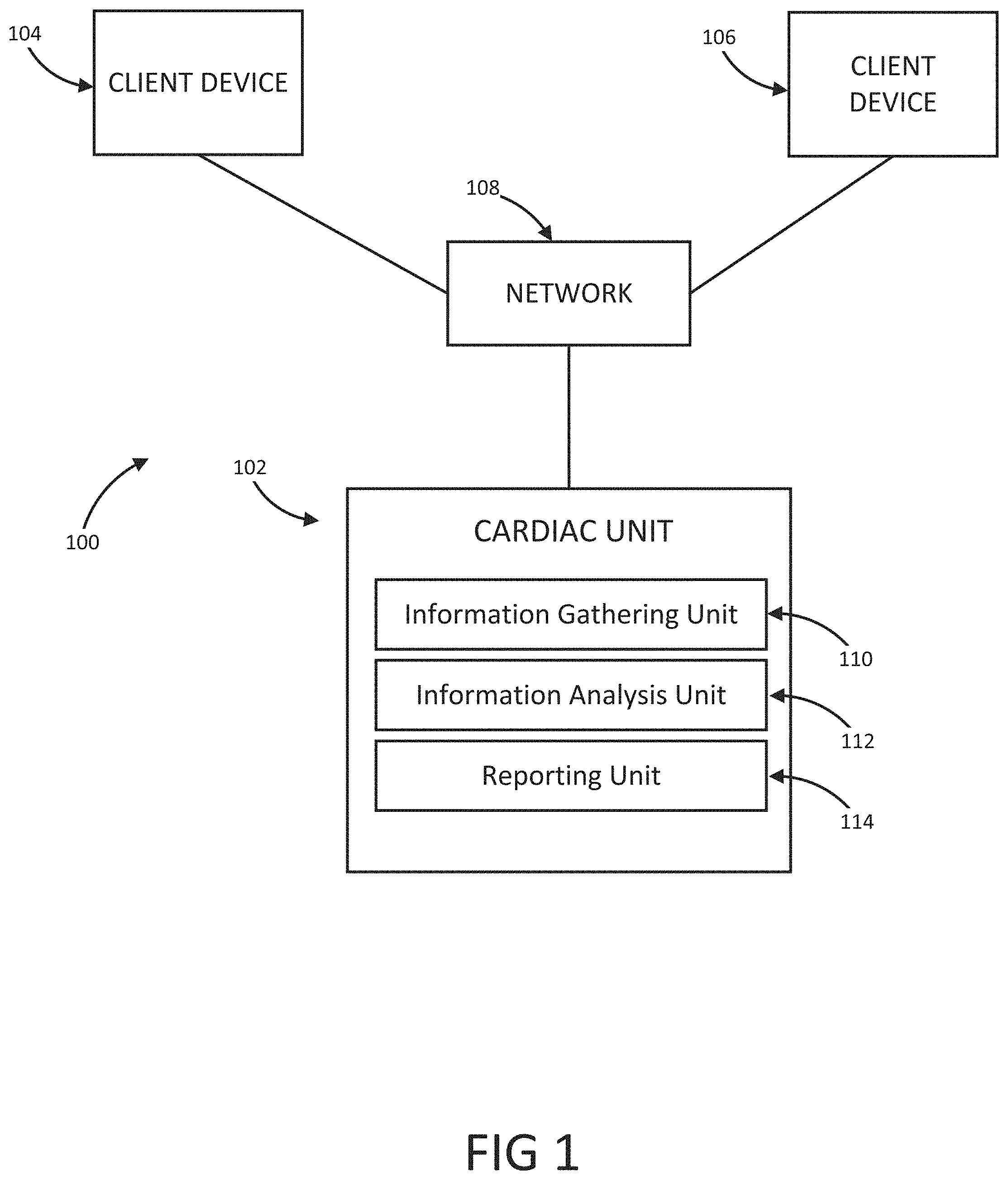
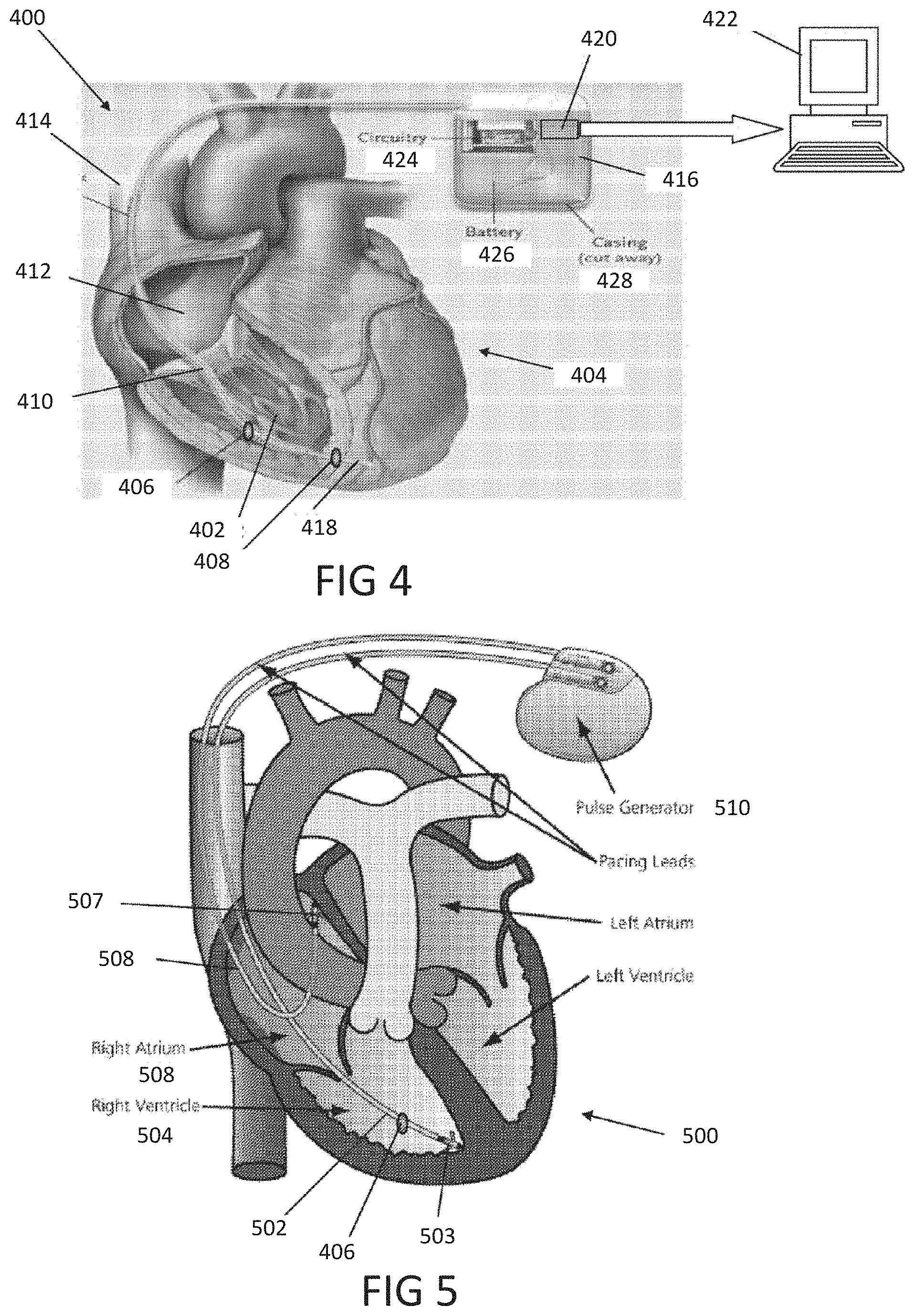
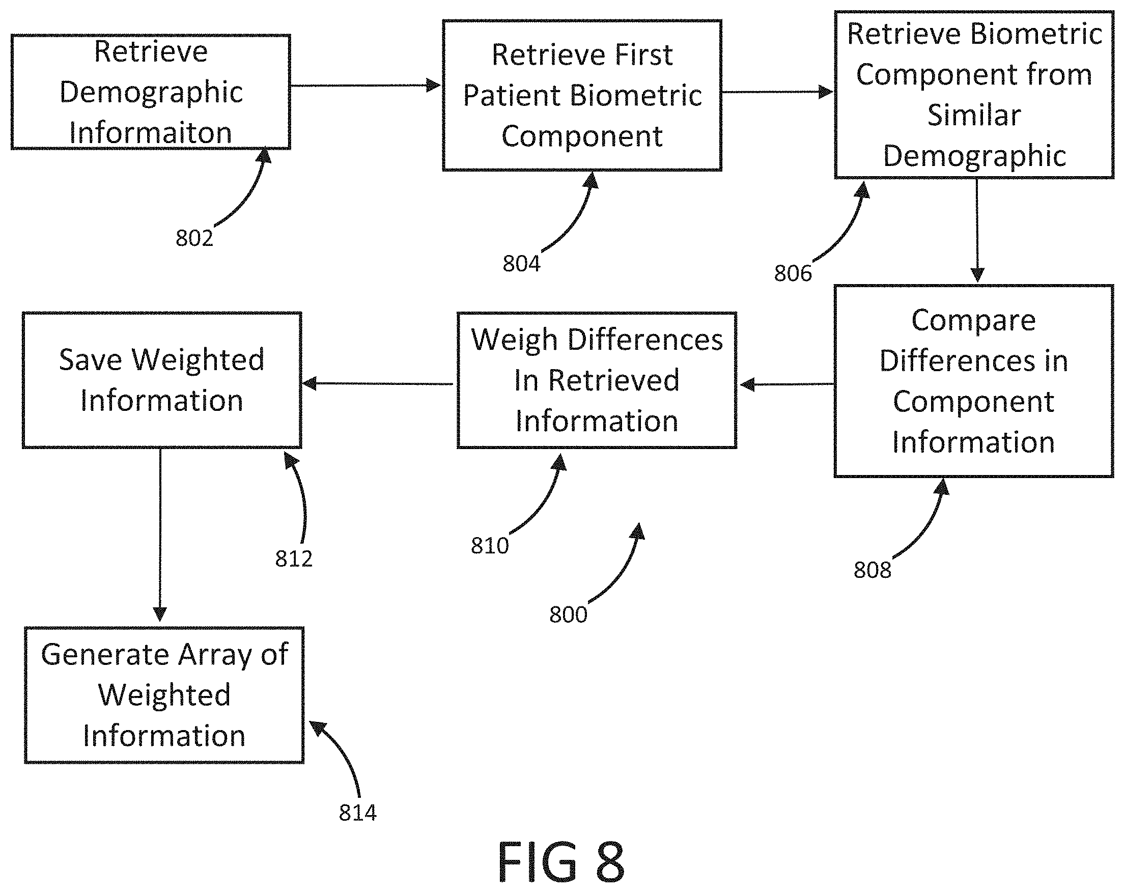
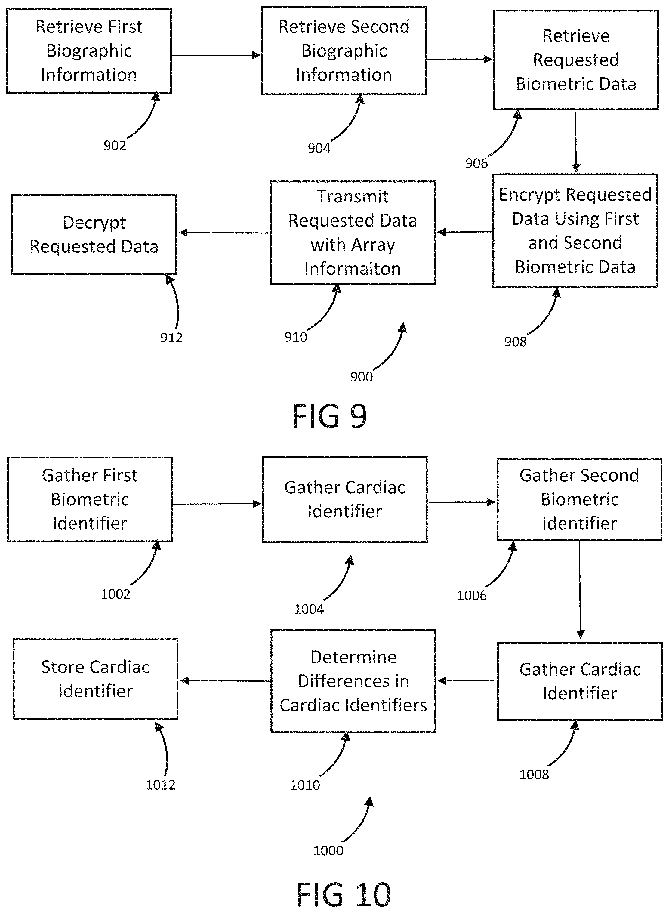
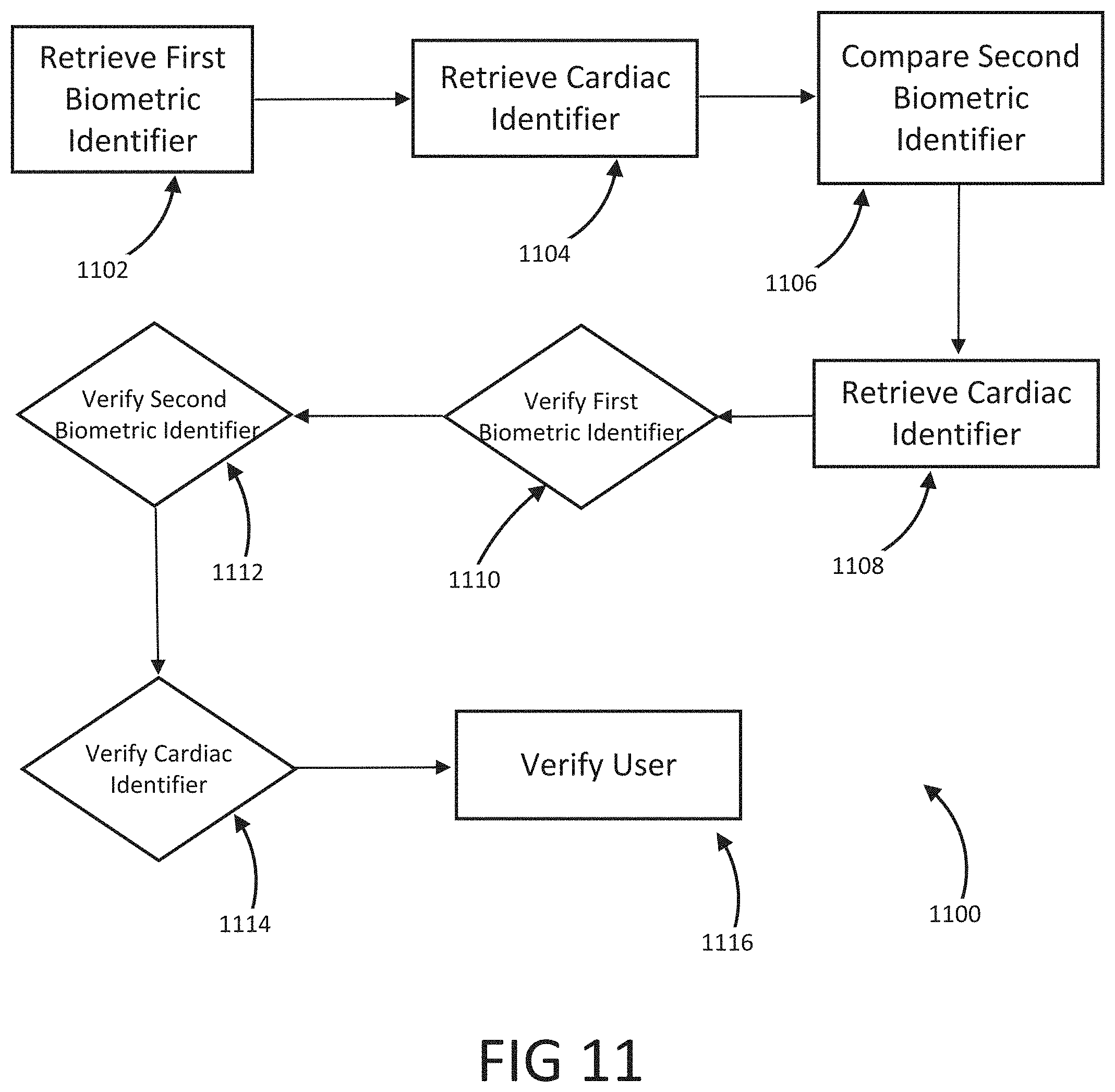
The present disclosure is a continuation of U.S. Application No. 63/046,900, filed on Jul. 1, 2020, which is incorporated by reference in its entirety. Millions of confirmed cases of COVID-19 have been identified, including hundreds of thousands of deaths having been reported to the World Health Organization (“WHO”). The risk of severe disease and death has been highest in elderly people and in persons with underlying noncommunicable diseases (NCDs), such as hypertension, cardiac disease, chronic lung disease and cancer. Limited data describe clinical manifestations of COVID-19 that are generally milder in children compared with adults, but also show that some children do require hospitalization andintensive care. However, many patients develop a high or hyperinflammatory state secondary to a cytokine storm that is macrophage activation syndrome, or cytokine release syndrome and as aconsequence they develop a severe vasodilatory shock that is difficult to manage and requiresseveral strategies including immune-suppressive therapy, inotropic support, metabolic support andin severe cases cardiac circulatory support including extracorporeal membrane oxygenation. The management of this becomes very challenging without objective monitoring.Therefore, a need exists for a temporary monitoring solution. Systems, methods, features, and advantages of the present invention will be or will become apparent to one with skill in the art upon examination of the following figures and detailed description. It is intended that all such additional systems, methods, features, and advantages be included within this description, be within the scope of the invention, and be protected by the accompanying claims. One embodiment of the current disclosure includes an identification system including, a first biometric identifier, a second biometric identifier, a cardiac identifier logically related to the first and second biometric identifiers, where the identity of a user is verified using the biometric identifiers and the cardiac identifier. The accompanying drawings, which are incorporated in and constitute a part of thisspecification, illustrate an implementation of the present invention and, together with the description, serve to explain the advantages and principles of the invention. In the drawings: Referring now to the drawings which depict different embodiments consistent with the present invention, wherever possible, the same reference numbers will be used throughout the drawings and the following description to refer to the same or like parts. The cardiac monitoring unit will monitor oxygen level, cardiac output and pressure in patients in the intensive care unit admitted with severe COVID-19 infection, avoiding need for placement of Swan-Ganz catheter, minimizing blood drawn and having an objective estimated ofpatient oxygenation that is reliable and easily transmitted to a wireless device. The traditional practice of placement of a Swan-Ganz Catheter requires close contact with patient, repetitive calibration and requires nursing staff to take blood samples from catheter every time the clinician requires a measurement of mixed venous Oxygen. The traditional approach also requires the clinician to actively manipulate the catheter to obtain measurement of pressure and cardiac output. Patients receiving a Swan-Ganz catheter are at a high risk of causing systemic infection, consequently, the catheter should not remain inserted into the patient longer than 7 days. If after 7 days, the patient still requires monitoring, then the patient will have to have a new catheter inserted. On the other hand, after a few days of having the catheter in place the information may not be as accurate and it can become difficult to obtain wedge pressure. Patients with moderate to severe COVID-19 infection and lung disease, can have varying manifestations of the disease, from mind pneumonitis to full ARDS (acute respiratory distress syndrome), and some patients can have normal tissue oxygenation while showing low oxygen saturation by traditional external oxygen saturation monitoring which are placed on patients finger or ear lop, these traditional oxygen monitors can capture inaccurate true oxygen saturation. It has been described that it may be two different phenotypes of lung disease, Type L (of Type 1) and Type H (or Type 2). Patients typically present with Type L disease, which is characterized by normal lung compliance and gas volume in the present of hypoxemia. These patients may improve, or they may worsen. About 20-30% of patients had, or evolved to Type H disease, characterized by decreased lung compliance and increased edema and lung weight. The transition from Type L to Type H may be due to the evolution of the COVID-19 pneumonia on one hand and the injury attributable to high-stress ventilation on the other. Type L patients can still be placed on the ventilator bybut with higher tidal volumes with lower positive end expiratory pressure (PEEP), while Type H patients should be treated as severe ARDS, including higher PEEP, if compatible with hemodynamics, prone positioning and ECMO. As one having ordinary skill in the art will recognize, having an objective measurement of central mixed venous saturation will help differentiate between Type L and Type H and provide the best method of treatment and will allow for a determination of what patients need escalation of care to ECMO or a different strategy of therapy. The cardiac monitor will allow early identification of patient transitioning from Type L to Type H and intervene early, thus prevention complication and death. Also, the monitor may allow physicians to allow a more permissive hypoxia and prevent intubation since some of these cases intubation and mechanical ventilation can worsen clinical status. Using the cardiac monitor as a temporary monitor is convenient and could also be used in non-intensive care unit setting since it does not require specialized monitoring or specialized nursing skills. Also, the data is remote, so it can be used in regular COVID-floor units, facilitating work and oxygen monitoring remotely. Temporary monitoring with the cardiac unit will help monitor patients with moderate COVID-19 infection and that can be treated at home but currently, because of the lack of reliable and available monitors, are being treated at the hospital. They can have the monitor at home during infection to make sure that they maintain adequate oxygenation and identify early deterioration so patients can come to the hospital for further treatment if needed. The temporary monitor will be also an essential tool to monitor response to therapy e.g. Infusion of convalescent plasma or antiretrovirals. The information gathering unit 110 and information analysis unit 112 may be embodied by one or more servers. In one embodiment, the network 108 is a cellular network, a TCP/IP network, or any other suitable network topology. In another embodiment, the row identification device may be servers, workstations, network appliances or any other suitable data storage devices. In another embodiment, the communication devices 104 and 106 may be any combination of cellular phones, smart phones, telephones, tablet, personal data assistants, or any other suitable communication devices. In one embodiment, the network 108 may be any private or public communication network known to one skilled in the art such as a local area network (“LAN”), wide area network (“WAN”), peer-to-peer network, cellular network or any suitable network, using standard communication protocols. The network 108 may include hardwired as well as wireless branches. In one embodiment, the network 108 may be any private or public communication network known to one skilled in the art such as a Local Area Network (“LAN”), Wide Area Network (“WAN”), Peer-to-Peer Network, Cellular network or any suitable network, using standard communication protocols. The network 108 may include hardwired as well as wirelessbranches. Referring to These physiological parameters provide data that can be used to identify and monitororgan perfusion, congestion in the chest cavity, and the degree of compensation or decompensation in patients with chronic cardiopulmonary failure or other types of cardiopulmonary disease. When coupled with cardiac output measurements, this data enables thecalculation of oxygen transport and oxygen consumption; early identification of impending oractual global tissue hypoxia; a determination of the cause of a hypoxic episode; an assessment ofthe response of a patient to a treatment of hypoxia; and a prediction of patient survival based onan underlying cause of a hypoxia episode and on the patient's response to the hypoxia treatment. Oxygen sensor 406 is approximately less than 1 cm in diameter and is positioned alongthe length of a lead 410 that passes through a right atrium 412 and a superior vena cava 414 atabout 3-4 cm above the tip of the lead. Pressure sensor 408 is positioned toward the end of lead 110, embedded in the wall of the right ventricle towards the apical septum 402. Lead 410 and sensor 406 are inserted intravenously into the right ventricle through the subclavian or cephalic vein of the patient. Lead 410 connects to a control module 416 positioned in a subcutaneous device pocket in the sub clavicular region of the patient, which pocket is formed by a small cutaneous incision, as in currently performed during the implantation of a pacemaker. Lead 410 is between 5-7 mm thick and is typically about 5 mm thick. A tip of 418 of lead 410 is anchored in the myocardium of heart 404 by soft tines or a tiny screw (not shown). A steroid elutes fromtip 418 to decrease inflammation at the tip-myocardium interface, thus improving the chronicity of sensor system 400. As a result, the sensor system 400 is able to remain implanted for long periods of time, allowing longer monitoring of physiological parameters. Measurement data is transmitted from oxygen sensor 406 and pressure sensor 408 to control module 416 along lead 410. Control module 416 includes a wireless communication module 420, such as an antenna coil. Communication module 420 wirelessly communicates the measurement data to a remote computer 422 for display, storage, or processing. Computer 422 may be, for instance, a clinician's computer, a patient's computer, or a handheld computing device. Communication between control module 416 and computer 422 may be periodic or upon request by computer 422. For instance, computer 422 may calculate both a continuous CvO2 level and an average CvO2 level at a preselected timing interval. Also, once a baseline CvO2 of the patient is obtained, an alarm setting can be programmed that will be activated at predetermined levels of CVO2, thus allowing early recognition of a decline or a decompensated status. Control module 416 also includes control circuitry 424 that controls the operation of sensor 406 and communication module 420. A lithium battery 426 in control module 416 supplies power to control circuitry 424, communication module 420, and sensor 406. The lifetime of battery 426 is typically in the range of 5-10 years and depends on factors such as the output voltage of control module 416, the resistance of lead 410 and sensor 416, and thefrequency and duration of use of the battery 426. The components in control module 108 are enclosed in a biocompatible casing 428. Oxygen sensor 406 and pressure sensor 408 are hermetically sealed devices made of titanium, iridium, or another biocompatible material that is pharmacologically inert, nontoxic, sterilizable, and able to function in the environmental conditions of the body. Ideally the material is not affected by stress cracking or metal ion oxidation. Circuitry in sensor 406 and circuitry in sensor 408 control the operation of measurement devices housed in sensors 406 and 408 and control the communication between the sensors and control module 416. A light emission module in oxygen sensor 406 includes a red (660 nm) and/or infrared (880 nm) light emitting diode (LED) hermetically sealed in a sapphire capsule. The LED emits light which illuminates blood in the right ventricle. The amount of light reflected by the blood, which is indicative of the oxygen saturation (i.e., the CvO2) is detected by a photodetector. A titanium pressure sensing membrane mounted on pressure sensor 408 measures fluid pressureand pulse pressure in the right ventricle or right atrium. A set of electrodes mounted on the external surface of pressure sensor 408 measures the impedance of tissue in the chest cavity, such as cardiac tissue and pulmonary tissue, at a digital rate of 128 Hz. Impedance measurements allow for portioned analysis of contractile cardiac function and pulmonary ventilation function. Average pulmonary impedance, e.g., averaged over a period of 72 hours or more, provides a baseline value against which an instantaneous impedance measurement can be compared. Signal processing of the impedance data allows deviations from baseline impedance values to be detected. For instance, a decrease in lung impedance is indicative of increasing fluid content and congestion in the lungs, which can lead tocongestive heart failure. In some embodiments, the sensor system is integrated with another implantable diagnostic or therapeutic device, such as a prophylactic implantable cardioverter defibrillator (ICD), a biventricular ICD, or a permanent pacemaker (PPM). In general, when the sensor system is integrated with another implantable device, certain structures (e.g., lead 410 in Referring to In some embodiments, pressure sensor 408 is positioned at the end of atrial lead 506. In some instances, atrial lead 506 is directed toward the base of the inter-atrial septum (not shown) such that pressure sensor 408 is embedded in the wall of the right atrium. The measurements of the right atrial pressure provided by the pressure sensor 408 located on the right atrial lead generally are more accurate than measurements of the right ventricular pressure provided by a pressure sensor located on a right ventricular lead (e.g., sensor 408 in Referring to In one embodiment, the anchor 503 that anchors the lead 502 into the myocardium of a right ventricle 504 is detachable form the lead 502 for removal from the heart. In another embodiment, the tip of the lead 502 connected to the myocardium is broken off to allow the lead 502 to be removed from the heart. In another embodiment, the anchor 503 the anchor is a separate unit from the lead 502 with the anchor 503 separating from the lead 502 when a specificmotion, i.e. twisting, bending, etc. is performed on the lead 502. In another embodiment, the anchor 503 may be retracted from the myocardium such that the anchor 503 and lead 502 may beremoved together. In one embodiment, the information analysis unit 112 uses right ventricular pressures, right atrial pressure, and mixed venous oxygen saturation, to generate a better understanding of patient hemodynamic status at any time and able to calculate cardiac output, and tissue oxygenations. The information analysis unit 112 may combine this information with currently known information including, but not limited to, percentage to RV pacing, the burden of Atrial fibrillation or ectopy, activity level, thoracic impedance, respiratory patterns and ventricular arrhythmias. These measurements will provide a clinician a more accurate assessment of patient hemodynamics status to make the best determination of therapies. This hemodynamic data will provide feedback on patients with electrical disturbance to determine the severity of arrhythmia and the need for ICD shock, thus either ensuring appropriate ICD therapy or prevention inappropriate ICD therapies in patients, a therapy that if applied without indication could be harmful to patients. Having a combination of hemodynamics e.g. right ventricular pressures, right atrial pressure and mixed venous oxygen saturation, provides a better understanding of patient hemodynamic status at any time, and also allows for the calculation of cardiac output and tissue oxygenations. These measurements combined with current available measurements in ICDs and BiVICD, which includes, but is not limited to, percentage to RV pacing, burden of atrial fibrillation or ectopy, activity level, thoracic impedance, respiratory patterns and ventricular arrhythmias; will provide a more accurate assessment of patient hemodynamics status to make the best determination of therapies. In one embodiment, an index that is combined with current measurement plus the oxygen monitor measurement that generates an alert for imminent acute decompensation, hemodynamic imbalance, predictor of further decompensation and clinical stability of patient. This hemodynamic data will provide a feedback on patient with electrical disturbance to determine severity of arrhythmia and need for ICD shock, thus preventing inappropriate ICD therapies in patients, therapy that if apply without indication could be harmful to patients. In one embodiment, once a user is authenticated, identification information may be incorporated into a digital record including, but not limited to, a blockchain. In another embodiment, the blockchain verification tokens are compliant with W3 standards or other heath care validation standards. In another embodiment, the user's medical records and vital statistics are stored in the user's blockchain where they can be validated for third parties requiring the medical information. In one embodiment, the verified information may be used to produce a bar code or a QR that uses gathered biometric information as the encryption key. While various embodiments of the present invention have been described, it will be apparent to those of skill in the art that many more embodiments and implementations arepossible that are within the scope of this invention. Accordingly, the present invention is not tobe restricted except in light of the attached claims. An identification system including a first biometric identifier, a second biometric identifier, a first cardiac identifier logically related to the first biometric identifier, a second cardiac identifier logically related to the second biometric identifier, where the identity of a user is verified using the biometric identifiers and the cardiac identifiers. 1. An identification system including:
a first biometric identifier; a second biometric identifier; a first cardiac identifier logically related to the first biometric identifier; a second cardiac identifier logically related to the second biometric identifier, wherein, the identity of a user is verified using the biometric identifiers and the cardiac identifiers. 2. The system of 3. The system of 4. The system of 5. The system of 6. The system of 7. The system of 8. The system of 9. The system of 10. The system of 11. A method of identifying a user of a device, the method including the steps of:
gathering a first biometric identifier; gathering a second biometric identifier; logically relating a first cardiac identifier to the first biometric identifier; logically relating a second cardiac identifier to the second biometric identifier, verifying the user using the biometric identifiers and the cardiac identifiers. 12. The method of 13. The method of 14. The method of 15. The method of 16. The method of 17. The method of 18. The method of CROSS-REFERENCE TO RELATED APPLICATIONS
BACKGROUND OF THE INVENTION
SUMMARY OF THE INVENTION
BRIEF DESCRIPTION OF THE DRAWINGS
DETAILED DESCRIPTION OF THE INVENTION