ADAPTABLE SUCTION TUBING AND LIGHT APPARATUS FOR SURGICAL RETRACTORS
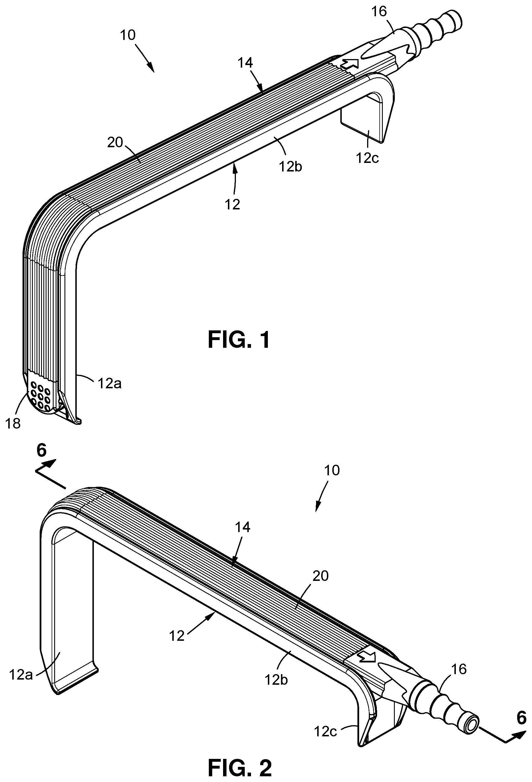
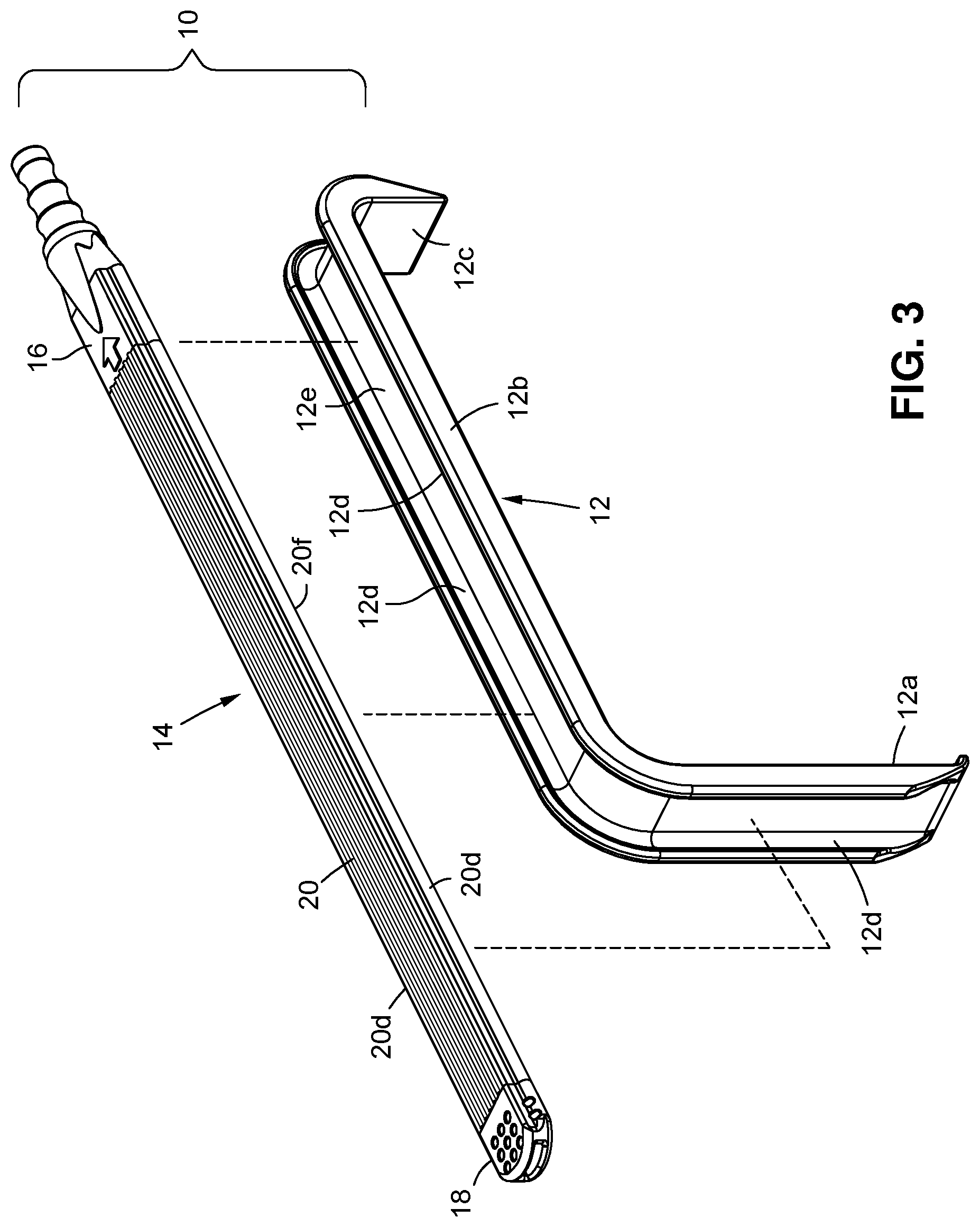
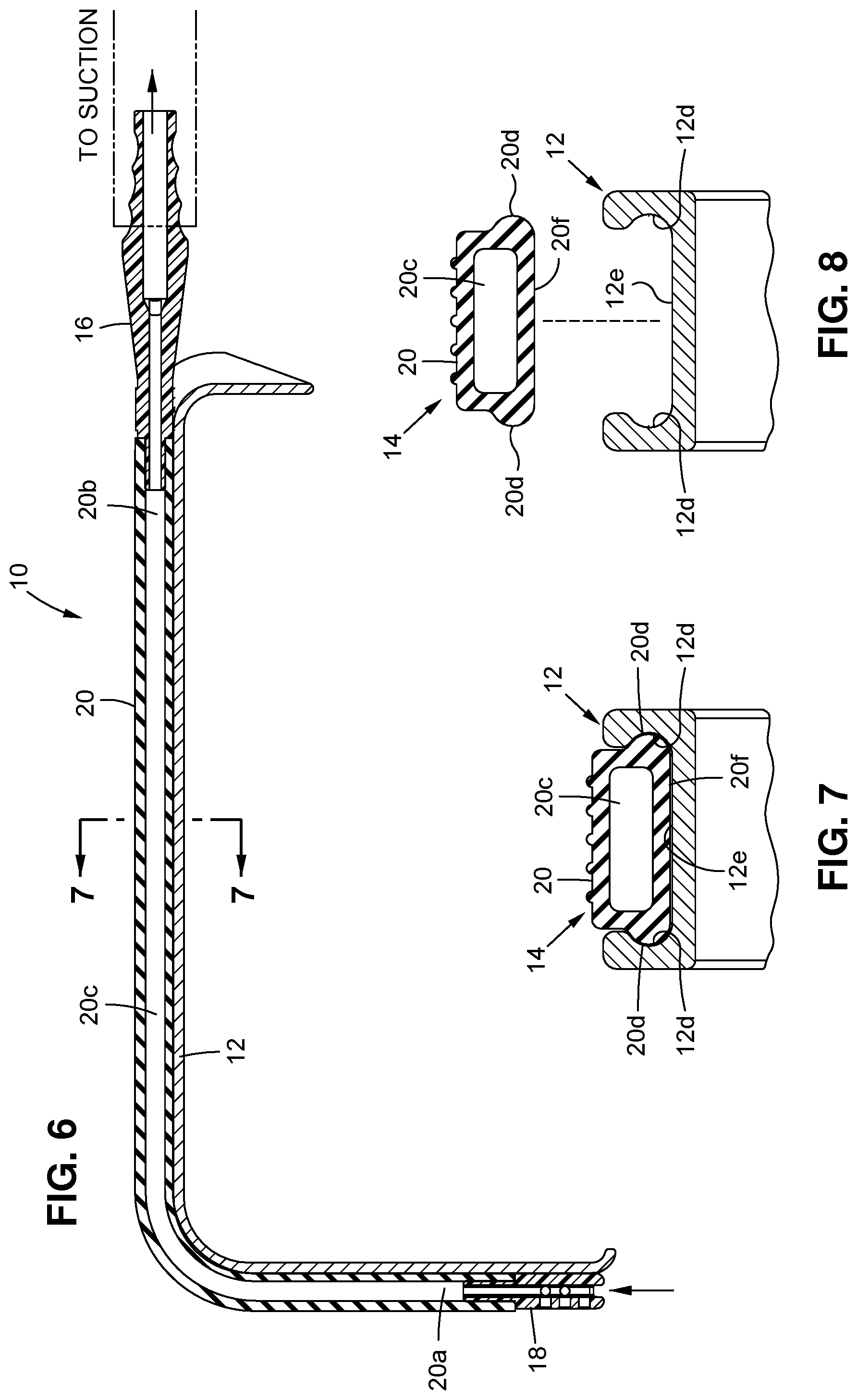
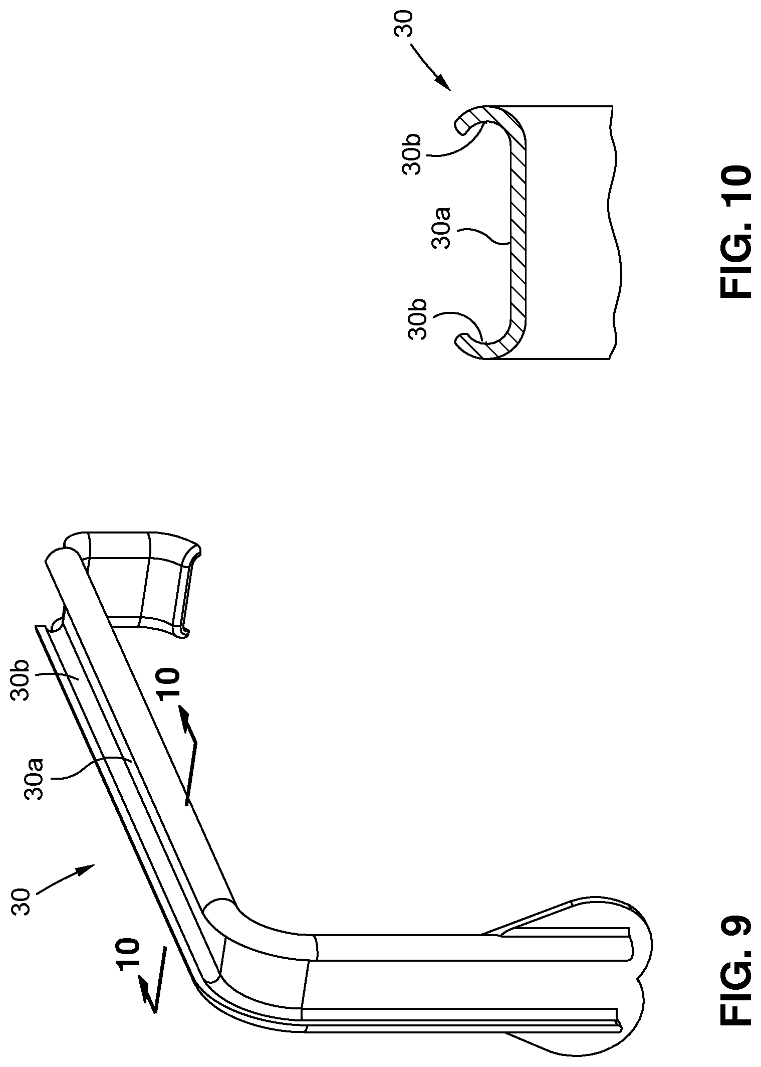
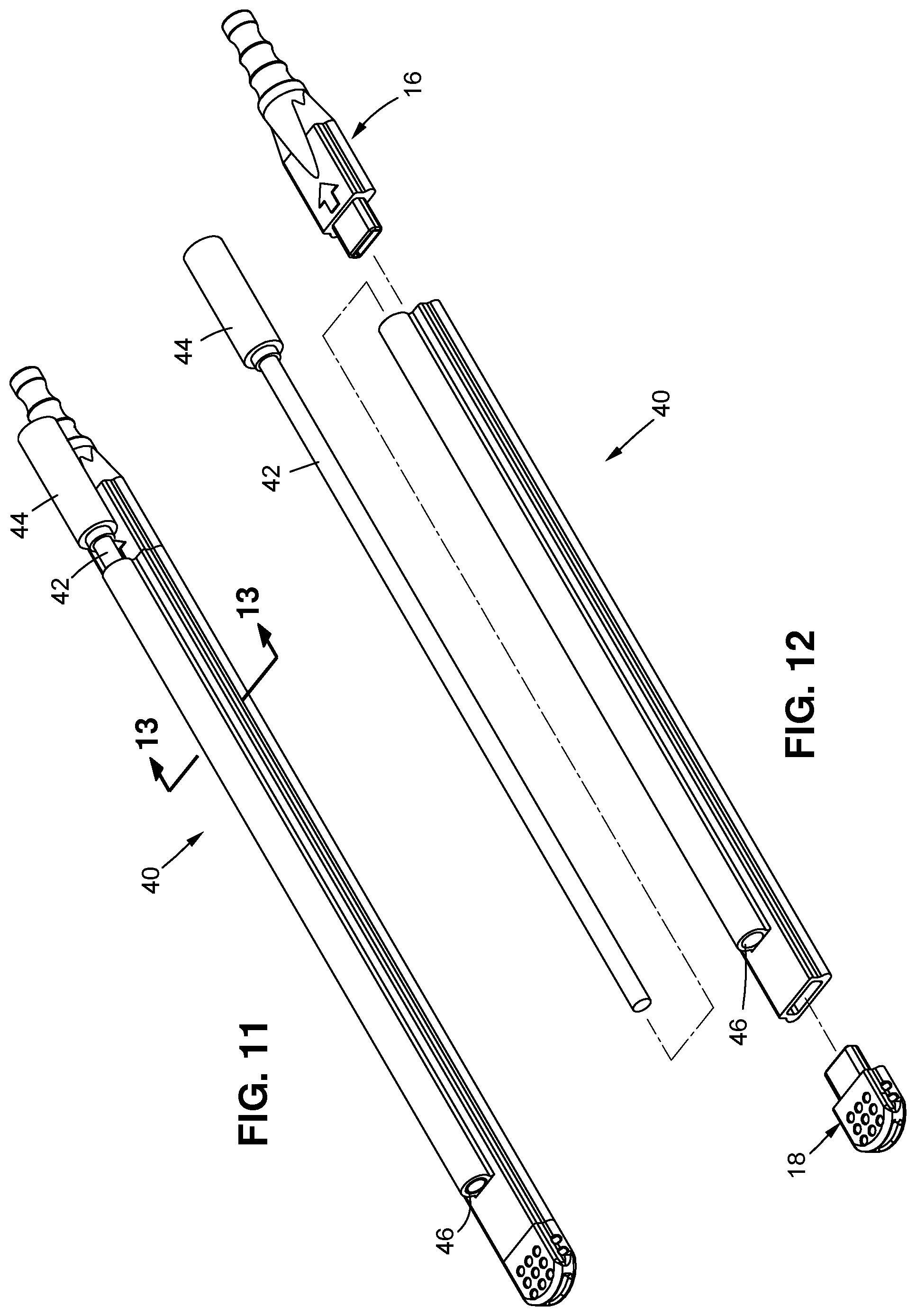
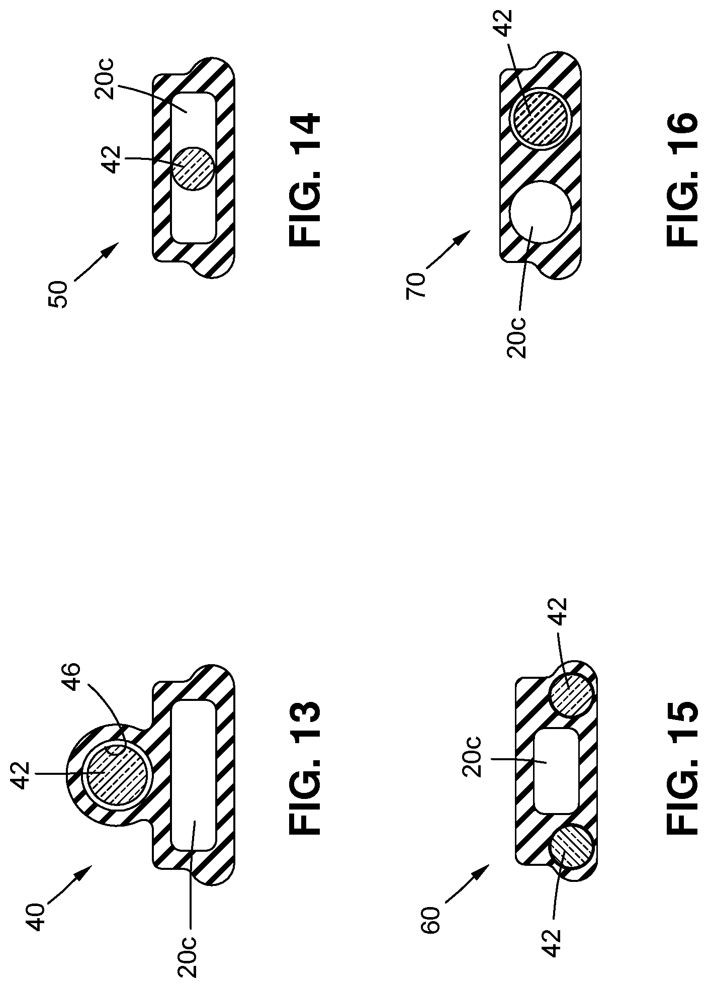
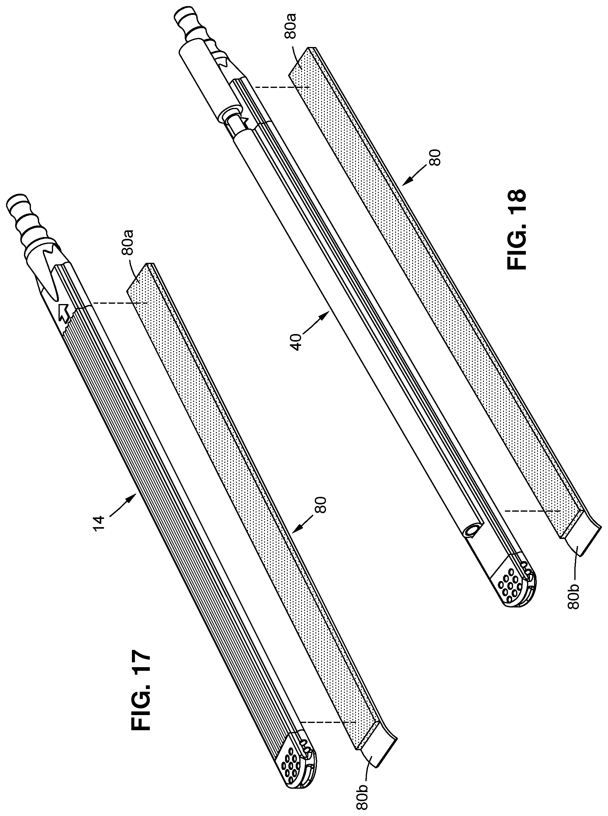
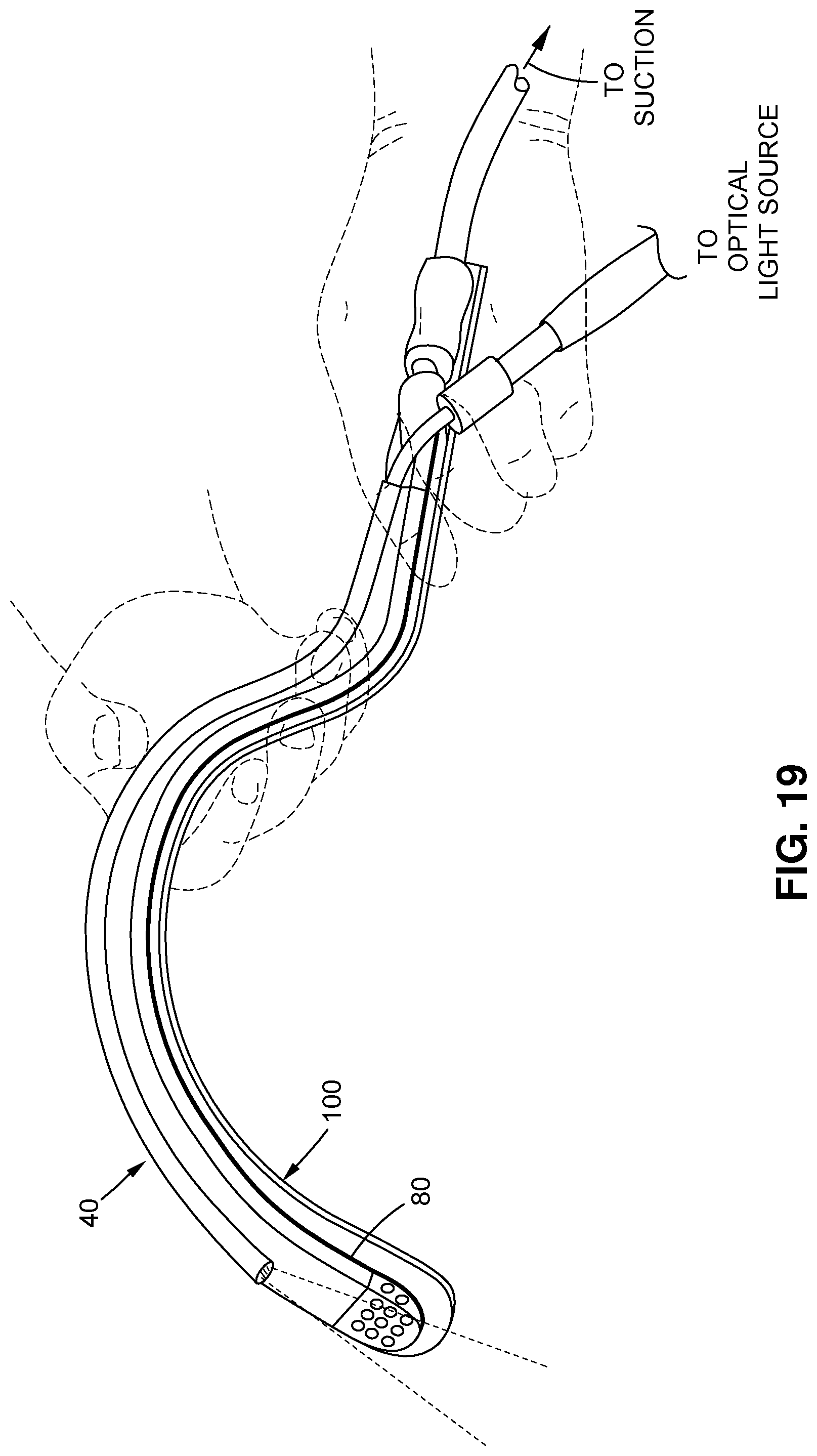
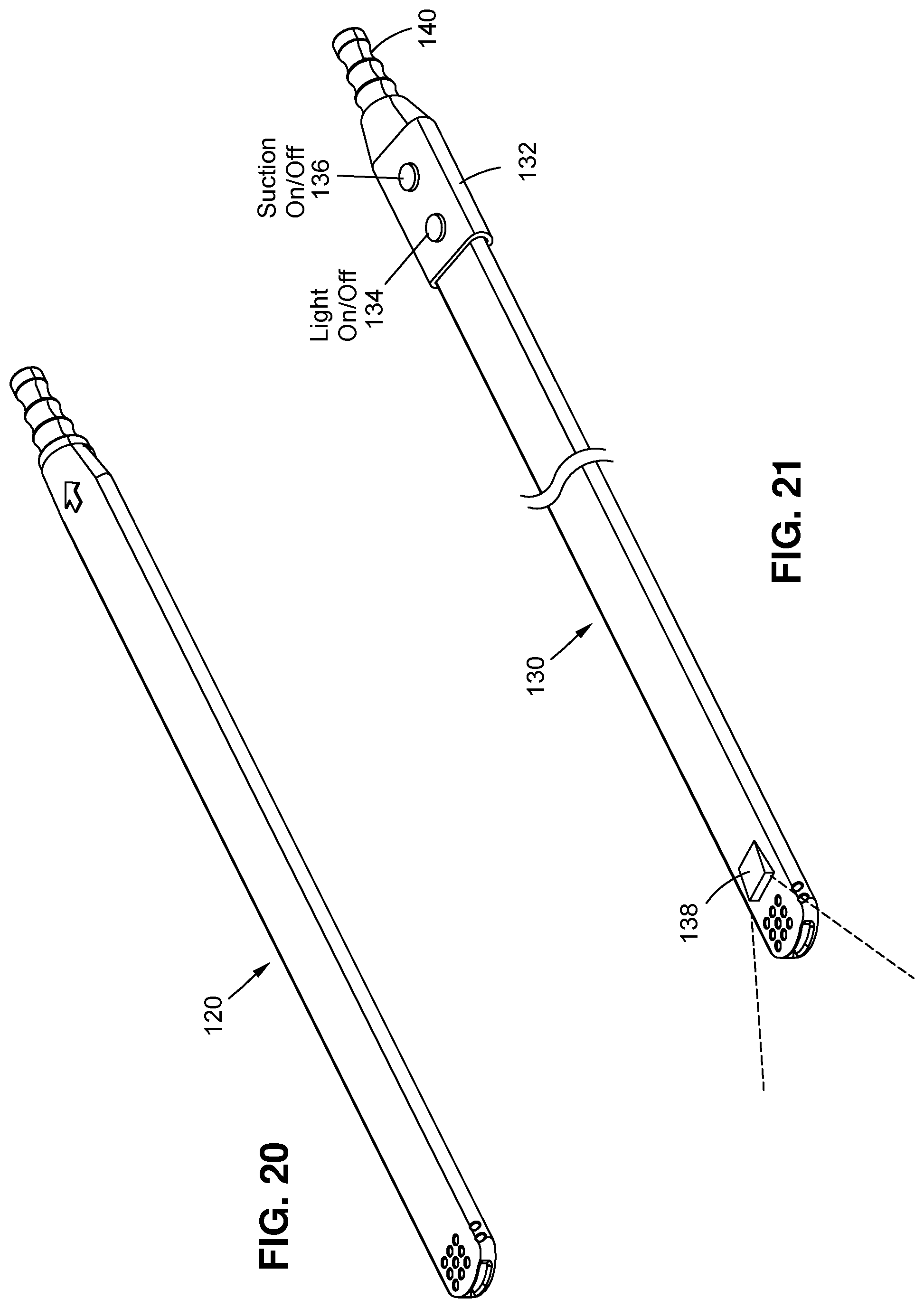
The present invention relates to surgical retractor that is used by a surgeon in surgery. More particularly, the surgical retractor uses an adaptable suction and light overly that is flexible and conformed to the contour of a retractor. There are many types of surgical retractors used today in surgical field. Some of these retractors have suction and light, and some are just simple plain retractors. Those retractors with suction and light are having pre-formed tubular jackets over the instrument for providing suction and light and cannot be removed or disassembled from instrument for better sterilization processes. Normally the tubular jacket are made of stainless steel material and it is spot welded to the instrument. Furthermore the function of the suction tube is very limited and can only evacuate the smoke from the surgical field. In most cases when surgeon is performing an operation, he or she needs another suction device to evacuate the fluid from the field in order to visually examine and evaluate the surgical field. However, this invention overcomes the shortcomings of prior art by using a suction tubing device to be placed right over a surgical retractor and can easily be removed or peel off after usage. The surgeon has options to place the suction tubing anywhere over the retractor instrument. He or she can use it for smoke evacuation or for fluid evacuations as needed for the surgical procedures. The suction and light tubing apparatus specifically designed for one time use and therefor it is disposable and no need for re-sterilization process. An adaptable suction tubing apparatus for a surgical retractor is disclosed. The suction tubing apparatus comprises a suction tip connector, an extruded rectangular tubing and an end suction connector. All components have side protrusions or bumps for nesting over the top surface of a surgical retractor channels. These side protrusions provides snug fit with a surgical retractor. The suction tubing apparatus is designed for one time use and has low profile and conformed to the contour of any retractors perfectly. It is object of present invention to have a double sided adhesive tape on the bottom surface of the tubing apparatus for the placement over the top surface of a standard surgical retractor. It is also object of present invention to have combination of suction and fiber optic light for this apparatus. Furthermore the fiber optics lights has universal end connector and can be used with many different light source machines. It is yet another object of the present invention to configure at least one dedicated lumen in suction strip for the fiber optic adjacent to suction lumen or within suction lumen. Further objects and advantages of this invention will become apparent from consideration of the drawings and descriptions that follow. The drawings constitute a part of this specification and include exemplary embodiments to the invention, which may be portrayed in various forms. It is to be understood that in some instances various aspects of the invention may be exaggerated or enlarged to facilitate an understanding of the invention. Detailed descriptions of the preferred embodiment are provided herein. It is to be understood, however, that the present invention may be embodied in various forms. Therefore, specific details disclosed herein are not to be interpreted as limiting, but rather as a basis for the claims and as a representative basis for teaching one skilled in the art to employ the present invention in virtually any appropriately detailed system, structure or manner. The adaptable suction tubing apparatus 14 is made of flexible polymer material such as PVC, or silicone and placed right over the top surface 12 The suction tip connector has pluralities of suction ports on top 18 Furthermore, all the components are having side protrusion 18 An assembled cross sectional view of present invention is shown in Now referring to Alternatively, the fiber optic strand 42 can be placed inside suction lumen 20 Another suction strip embodiment 70 can have two parallel lumens next to each other for both suction 20 While this invention is susceptible to embodiments in many different forms, this specification and the accompanying drawings disclose only some specific forms as examples of the invention. The invention is not intended to be limited to the embodiments as described; however, the scope of the invention is pointed out in the appended claims. An adaptable suction tubing apparatus for a surgical retractor is disclosed. The suction tubing apparatus comprises a suction tip connector, an extruded rectangular tubing and an end suction connector. All components also have side protrusions or bumps for nesting into top channels over the top surface of a surgical retractor. These side protrusions provides snug fit within a surgical retractor. Optionally the tubing can have double sided adhesive tape for placement over the top surface of a standard surgical retractor. The suction tubing apparatus is designed for one time use and has low profile and conformed to the contour of any retractors perfectly. 1- An adaptable suction tubing apparatus for a surgical retractor comprises:
an extruded rectangular tubing having distal and proximal ends, said tubing includes at least one lumen for purpose of suctioning, and having protrusions at its sides for mating with a surgical retractor top surface channels, and; a hollow tip connector, said hollow tip connector having plurality of ports for purpose of evacuation at one end, and at the other end attached to said rectangular tubing at its distal end; and; a hollow end connector, said end connector connects to external suction source at one end and at the other end attached to said rectangular tubing at its proximal end. 2- An adaptable suction tubing apparatus for a surgical retractor according to 3- An adaptable suction tubing apparatus for a surgical retractor according to 4- An adaptable suction tubing apparatus for a surgical retractor according to 5- An adaptable suction tubing apparatus for a surgical retractor comprises:
an extruded rectangular tubing having distal and proximal ends, said tubing includes at least one lumen for purpose of suctioning and at least one lumen for purpose of passing fiber optics light, and having protrusions at its sides for mating with a surgical retractor top surface channels, and; a hollow tip connector, said hollow tip connector having plurality of ports for purpose of evacuation at one end, and at the other end attached to said rectangular tubing at its distal end; and; a hollow end connector, said end connector connects to external suction source at one end and at the other end attached to said rectangular tubing at its proximal end. 6- An adaptable suction tubing apparatus for a surgical retractor according to 7- An adaptable suction tubing apparatus for a surgical retractor according to 8- An adaptable suction tubing apparatus for a surgical retractor according to 9- An adaptable suction tubing apparatus for a surgical retractor comprises:
an extruded rectangular tubing having distal, proximal ends, top surface and bottom surface, said tubing includes at least one lumen for purpose of suctioning and at least one lumen for purpose of passing fiber optics light, and; a hollow tip connector, said hollow tip connector having plurality of ports for purpose of evacuation at one end, and at the other end attached to said rectangular tubing at its distal end; and; a hollow end connector, said end connector connects to external suction source at one end and at the other end attached to said rectangular tubing at its proximal end, and; a double sided adhesive tape, said double sided adhesive tape having a top surface and bottom surface, said top surface attached to bottom of said rectangular tubing and said adhesive bottom surface attached to top surface of a surgical retractor.FIELD OF THE INVENTION
BACKGROUND OF THE INVENTION
SUMMARY OF THE INVENTION
BRIEF DESCRIPTION OF THE DRAWINGS
DETAILED DESCRIPTION OF THE INVENTION