POLARIZATION INDEPENDENT FULL DUPLEX OPTICAL SWITCH
POLARIZATION INDEPENDENT FULL DUPLEX OPTICAL SWITCH CROSS REFERENCE TO RELATED APPLICATIONS This application claims the benefit of U.S. Provisional Application No. 60/313,828, filed August 22, 2001. BACKGROUND OF THE INVENTION This invention is concerned with optical switches for selectively connecting signals in a first array of optical channels to a second array of optical channels. Fiber optic transmission systems are desirable, particularly for linking computer or other components requiring the movement of large amounts of data at high rates, because of their high information transmission capacity, immunity from electromagnetic interference, and security from unauthorized interception. Such optical transmission systems typically utilize switching devices for control purposes and for transferring data from one link to another. Such switching has been accomplished in the prior art using total internal reflection (TIR) switches (see, e.g., Soref, US Patent No. 4,385,799 and Soref, et al., US Patent No. 4,516,837-an improved design to allow efficient switching of unpolarized light), but these designs are polarization dependent, thus essentially discarding half the incoming light from an unpolarized beam. The switch disclosed in US Patent No. 4,385,799 can switch two polarizations and is considered "polarization independent" for narrowband signals, but for broadband operation, this switch must be implemented in a particular way to avoid polarization dependent losses. It would be desirable to have a switch that is polarization independent for broadband operation, can accommodate full duplex operation, and provides a redundant path for path protection or for diagnostics. SUMMARY OF THE INVENTION An optical switch for connecting an array of M optical channels to an array of N optical channels includes a polarizing beam splitter for separating a signal in each of the M optical channels into first and second orthogonally polarized signal
components and a first patterned polarization rotator for receiving the orthogonally polarized components from the polarizing beam splitter and rotating the polarization of one of the components in each signal, such that the first and second components in each signal have the same polarization. A first switch matrix for receiving the same- polarized components from the first patterned polarization rotator selectively routs each signal to one of N paths, while a second switch matrix receives the signals from the first switch matrix and selectively routs each signal to one of M paths. A second patterned polarization rotator receives the signals from the second switch matrix and rotates one of the polarized components of each signal, such that the first and second components of each signal are orthogonally polarized. A polarizing beam combiner receives the orthogonally polarized components from the second patterned polarization rotator and combines the first and second component in each signal, the combined components defining an output array of N optical signals aligned with the N optical channels. The optical switch may further include a polarization rotator between the first switch matrix and the second switch matrix to align the polarization of the signals from the first switch matrix with the optimal polarization direction for input to the second switch matrix. In a more particular embodiment, each of the M optical channels is divided into a 1 x 2 subchannel array; and each of the N optical channels is divided into a 2 x 1 subchamiel array, such that the first and second orthogonally polarized components can be oriented in a direction corresponding to either a column or a row of the subarrays, thereby permitting bidirectional signals to be simultaneously connected through the switch from the array of M optical channels to the array of N optical channels and from the array of N optical channels to the array of M optical channels. An output tap can be added to the switch and positioned to receive a constant fraction of the signal in each of the N channels, regardless of the states of the first switch matrix and the second switch matrix.
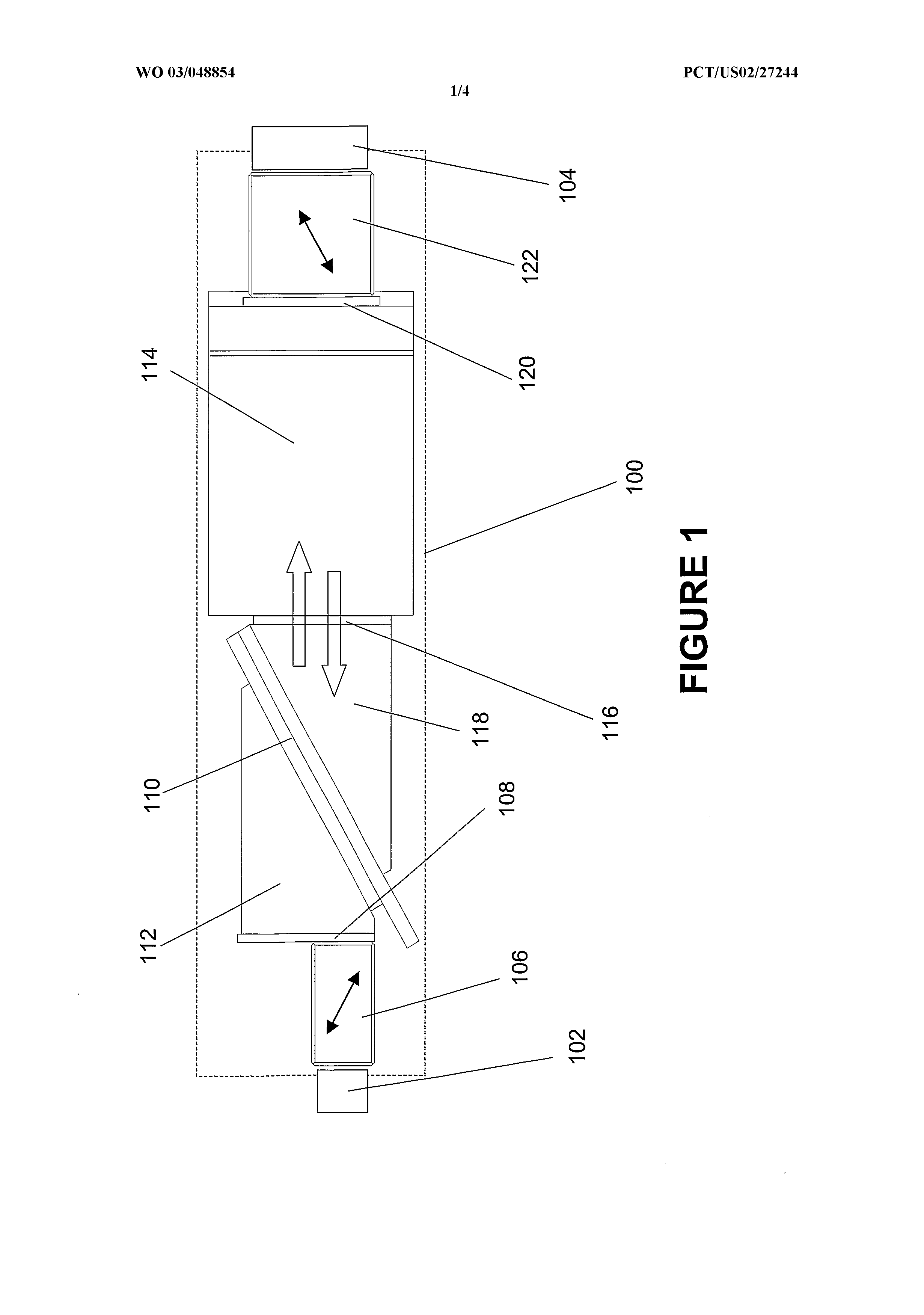
The arrays of M and N optical channels may, in more particular embodiments, be 1 x M and 1 x N optical fiber collimator arrays, or may be 1 x M and 1 x N beam arrays in free space. DESCRIPTION OF THE DRAWINGS Figure 1 depicts an optical switch. Figure 2 shows an arrangement of subchannel arrays within the optical channels that allows full duplex operation of the switch. Figures 3 and 4 depict two alternative designs of a switch matrix that make possible the addition of a diagnostic tap and a redundant input to the switch. DESCRIPTION OF THE INVENTION Figure 1 depicts an optical switch 100 for connecting an array 102 of M optical channels to an array 104 of N optical channels. The switch includes a polarizing beam splitter 106 for separating a signal in each of the M optical channels into first and second orthogonally polarized signal components. A first patterned polarization rotator 108 receives the orthogonally polarized components from the polarizing beam splitter and rotates the polarization of one of the components in each signal, such that the first and second components in each signal have the same polarization. A first switch matrix 110 receives the same-polarized components from the rotator and selectively routes each signal to one of N paths. The switch matrix 110 includes a multipixel liquid crystal cell, with coupling prisms on either side. Prism 112 couples the signals from the rotator 108 to the switch 110 and prism 118 couples the signals from the switch matrix 110 to the rotator 116. A second switch matrix 114, similar in design to the first switch matrix, receives the signals from the first switch matrix and selectively routes each signal to one of M paths. Total internal reflection (TIR) liquid crystal switches provide broad wavelength coverage and excellent cross talk suppression. The two switches can optionally be oriented orthogonal to each
other, with a polarization rotator 116 provided to align the polarization of the signals from the first switch matrix with the optimal polarization direction for input to the second switch matrix. Additional prisms analogous to prisms 112 and 118 are used to couple the signals into and out of the second switch matrix, but are not shown because of the orthogonal orientation of the second switch matrix 114. This design allows the switches to be optimized for a single polarization. If, for example, the switches work on the s polarization, the p polarization is separated and rotated at the input side, then switched. At the output of the switching stage, the s polarization is rotated to p and the two are recombined. This arrangement avoids the polarization dependent losses of the Soref (US Patent No. 4,385,799) design, thereby making broadband operation feasible, and also acts as a polarization trap. The cross talk generated in the switch can be of two types: same (s) polarization or rotated (p) polarization. To the first order, the p polarization cannot reach an output channel, because the polarization rotator and combiner will deviate from the optical path. A second patterned polarization rotator 120 receives the signals from the second switch matrix 114 and rotates one of the polarized components of each signal, such that the first and second components of each signal are orthogonally polarized. Finally, a polarizing beam combiner 122 receives the orthogonally polarized components from the second patterned polarization rotator and combines the first and second components in each signal, the combined components defining an output array of N optical signals that is aligned with the N optical channels 104. Polarization splitting requires switching two beams identically. This and a rotated second switch leaves unused area in each channel that can be used to route a receiving line that is switched identically to the transmitting line switching state. As depicted in Figure 2, each of the M optical channels may be made up of a 1 x 2 subchannel array 224, while each of the N optical channels is made up of a 2 x 1 subchannel array 226. With this arrangement, the first and second orthogonally polarized components can be oriented in a direction corresponding to either a column,
such as the column 228, or a row, such as the row 230, of the subarrays, thereby permitting signals to be simultaneously connected through the switch from the array of M optical channels to the array of N optical channels and from the array of N optical channels to the array of M optical channels. This allows the switch to function as a full duplex component, allowing simultaneous transmission and reception. Figure 3 illustrates additional features of the invention that make possible the addition of a diagnostic tap and a redundant input. An output tap 332 is positioned to receive a constant fraction of the signal in each of the channels, regardless of the states of the switch matrix 310. In addition, a redundant input 334 can be utilized to provide path protection for the device, i.e., if one part of a network of switches is broken, then the redundant input can be used to reestablish the broken connection. Figure 4 is similar to Figure 3, but shows an alternate design for the switch matrix 410, with an output tap 432 and a redundant input 434. In specific embodiments, the arrays of optical channels may be optical fiber collimator arrays or arrays in free space. The polarizing beam splitter and polarizing beam combiner may be provided by, e.g., birefringent crystal beam displacers or reflective polarizing beam splitters. The patterned polarization rotator may be a birefringent wave plate or an achromatic rotator. The first and second switch matrices are preferably liquid crystal switches. This invention provides switching of all outputs between two parallel sets of optical fibers. Consequently, the switch can perform signal or equipment monitoring without physically interrupting the fiber connections. This necessarily requires that the collimator array must be a two dimensional, rather than linear, array. Another advantage is that four parallel beams can be incorporated in each signal element of the array. Two of the paths are used for transmission and reception, while the other two are for the orthogonally polarized components. In addition, the switch design of this invention permits monolithic assembly, so that no fiber interconnects are required. The insertion loss and cross talk associated
with this design are comparable to the meshed binary tree architecture, with fewer liquid crystal cells, no cell laminations, and no beam blocks or index matching required. Furthermore, the design is readily scalable to more inputs, full duplex operation, and path protection. The preferred embodiments of this invention have been illustrated and described above. Modifications and additional embodiments, however, will undoubtedly be apparent to those skilled in the art. Furthermore, equivalent elements may be substituted for those illustrated and described herein, parts or connections might be reversed or otherwise interchanged, and certain features of the invention may be utilized independently of other features. Consequently, the exemplary embodiments should be considered illustrative, rather than inclusive, while the appended claims are more indicative of the full scope of the invention.
An optical switch (100) for connecting an array of M optical channels to an array (104) of N optical channels includes a polarizing beam splitter (106) to separate a signal in each of the M optical channels into first and second orthogonally polarized signal components and a first patterned polarization rotator (108) for receiving the orthogonally polarized components from the polarizing beam splitter and rotating the polarization of one of the components in each signal, such that the first and second components in each signal have the same polarization. A first switch matrix (110) for receiving the same-polarized components from the first patterned polarization rotator selectively routes each signal to one of N paths, while a second switch matrix (114) receives the signals from the first switch matrix and selectively routes each signal to one of M paths. A second patterned polarization rotator receives the signals from the second switch matrix and rotates one of the polarized components of each signal, such that the first and second components of each signal are orthogonally polarized. A polarizing beam combiner receives the orthogonally polarized components from the second patterned polarization rotator and combines the first and second component in each signal, the combined components defining an output array of N optical signals aligned with the N optical channels. CLAIMS: 1. An optical switch for connecting an array of M optical channels to an array of N optical channels, comprising: a polarizing beam splitter for separating a signal in each of the M optical channels into first and second orthogonally polarized signal components; a first patterned polarization rotator for receiving the orthogonally polarized components from the polarizing beam splitter and rotating the polarization of one of the components in each signal, such that the first and second components in each signal have the same polarization; a first switch matrix for receiving the same-polarized components from the first patterned polarization rotator and selectively routing each signal to one of N paths; a second switch matrix for receiving the signals from the first switch matrix and selectively routing each signal to one of M paths; a second patterned polarization rotator for receiving the signals from the second switch matrix and rotating one of the polarized components of each signal, such that the first and second components of each signal are orthogonally polarized; and a polarizing beam combiner for receiving the orthogonally polarized components from the second patterned polarization rotator and combining the first and second component in each signal, the combined components defining an output array of N optical signals aligned with the N optical channels. 2. The optical switch of Claim 1, further comprising a polarization rotator disposed between the first switch matrix and the second switch matrix, such that the polarization rotator aligns the polarization of the signals from the first switch matrix with the optimal polarization direction for input to the second switch matrix.
3. The switch of Claim 1, wherein: each of the M optical channels further comprises a 1 x 2 subchannel array; and each of the N optical channels further comprises a 2 x 1 subchannel array; such that the first and second orthogonally polarized components can be oriented in a direction corresponding to either a column or a row of the subarrays, thereby permitting signals to be simultaneously connected through the switch from the array of M optical channels to the array of N optical channels and from the array of N optical channels to the array of M optical channels. 4. The switch of Claim 1 , further comprising an output tap that is positioned to receive a constant fraction of the signal in each of the N channels, regardless of the states of the first switch matrix and the second switch matrix. 5. The switch of Claim 1 , wherein the array of M optical channels further comprises a 1 x M optical fiber collimator array and the array of N optical channels further comprises a 1 x N optical fiber collimator array. 6. The switch of Claim 1 , wherein the array of M optical channels further comprises a 1 x M array in free space and the array of N optical channels further comprises a 1 x N array in free space. 7. The switch of Claim 1, wherein the polarizing beam splitter further comprises a birefringent crystal beam displacer. 8. The switch of Claim 7, wherein the polarizing beam combiner further comprises a birefringent crystal beam displacer.
9. The switch of Claim 1, wherein the polarizing beam splitter further comprises a reflective polarizing beam splitter. 10. The switch of Claim 1 , wherein the polarizing beam combiner further comprises a reflective polarizing beam combiner. 11. The switch of Claim 1, wherein the patterned polarization rotator further comprises a birefringent wave plate 12. The switch of Claun 1, wherein the patterned polarization rotator further comprises an achromatic rotator. 13. The switch of Claim 1, wherein the first and second switch matrices further comprise liquid crystal switches.