A STRIP MEANS AND AN IMPROVED SUCTION ROLL FOR A MATERIAL WEB MACHINE AND AN ARRANGEMENT AND A METHOD FOR IMPROVING THE DURATION OF THE SUCTION ROLL
A strip means and an improved suction roll for a material web machine and an arrangement and a method for improving the duration of the suction roll The present invention generally relates to material web machines, such as fibre web machines. Fibre web machines include paper machines, tissue machines, board machines and pulp machines, for example. More particularly, the present invention relates to a strip means and a suction roll for a material web machine for improving the duration of the suction roll and an arrangement and a method for improving the duration of the suction roll. In connection with present invention, the attribute "material web machine" generally refers to processing machines for all kinds of web-like materials. In the following, the general attribute "material web machine" will be used in connection with the present invention. A web-like material is typically a material web, especially a fibre web, such as various paper webs, board webs, tissue webs, pulp webs and fabric webs, etc., for example. For the sake of simplicity, in the following a web-like material will be referred to by the attribute "web". The wearing of strip means, such as sealing strips and/or dewatering strips, for example, and the duration of their facing parts, such as a mantel and/or material, *become significant problems when the running speeds of material web machines are increased and when, at the same time, maintenance intervals are attempted to be extended. In the following, the sealing strips and/or dewatering strips and corresponding strip parts of material web machines are referred to by the attribute "strip means" for the sake of simplicity, and the facing parts of strip means, such as a surface of a mantel of a suction roll and/or roll surfaces in a wire part and/or press section are referred to by the attribute "facing surface" for the sake of simplicity. In order to achieve the desired operation, a longitudinal strip means is loaded substantially in a perpendicular direction against a facing surface so that it is in contact with the facing surface.
According to prior art, in order to achieve efficient functionality, such as an efficient suction effect and/or a leak-proof contact, for example, the strip means includes a longitudinal strip element and a longitudinal profile element, which is a U profile open in the direction of a facing surface, for example, and which functions as a holder of the strip element so that the strip element fitted to the holder protrudes from the profile element and, at least when loaded, is in the direction of the facing surface against the facing surface, which moves substantially in a transverse direction with respect to the length of the strip element, According to known prior art, an edge of the strip means or at least an edge of the strip element loaded against the facing surface is manufactured from a bending material. Thereby the strip element may be flexible in the direction of the radius of the roll. However, the problem is that the bending is not sufficient to provide an even contact. According to prior art, strip means or at least strip elements are manufactured in a desired total length and shaped to a desired profile shape by machining different rubber materials, resins and/or plastic-based materials, such as PE, PU, PPS, PEEK, PTFE, for example. To increase wear resistance during use, the materials to be machined may be reinforced with graphite. During use the strip element of the strip means is loaded, when it is fitted to the holder, towards the facing surface, whereby the longitudinal free edge of the strip element protruding from the holder is pressed against the facing surface. The most common loading solutions arranged between the holder and the strip element are various mechanical loading means, such as springs, for example, and loading solutions implemented directly or indirectly by means of a pressurised medium, for example. The FI patent application 955275 proposes that an inside loading element is arranged in a strip element of a sealing strip of a suction roll, by means of which the strip element can be locked tight to a holder in order to better position a protruding edge of the strip element with respect to a suction roll. The FI patent application 974023 proposes that locking means between a strip element
of a sealing strip of a suction roll and its holder, by means of which the strip element can be locked to a desired position in the holder, are fitted to a cavity on one side of the strip element and a separate second strip is fitted to a cavity on the other side of the strip element. Such solutions according to prior art are technically complex and therefore susceptible to damage. Another weakness is that significantly large friction and abrasive loading are generated between the strip means and the facing surface. A number of facing surface damage cases have shown that when lubrication is lacking abrasion may, with thermal fatigue, creates cracks which may strongly promote the generation and growth of cracks caused by loading stresses. Contrary to expectations, new abrasion tests have shown that the abrasion of a sealing strip significantly reduces fatigue life also without cracking. As a result of abrasion, fatigue life leading to breakage may even be reduced to one-tenth. An abrasion test performed under continuous water lubrication did not show generation of microcracks caused by thermal fatigue. This means that the weakening of fatigue strength occurs by some other mechanism. In addition, the graphite material of a strip element of a sealing strip may function like a noble metal and cause galvanic corrosion in a facing surface. Thus an abrasive contact of a sealing strip may cause damage to a facing surface in various ways. It is already known to be attempted to achieve lower friction coefficients by means of lubrication and a better material choice for a strip element. However, it is a continuous problem that a strip means or a strip element wears significantly fast and, in order to maintain sufficient functionality, wearing has to be continuously compensated by moving the strip element in the holder towards the facing surface by means of a loading means. Since the movement margin of the strip means or the strip element fitted to the holder is limited to compensate wearing and since it is not possible to use the entire strength of the edge part of the strip means or the strip element without damaging the facing surface, such as the surface of a mantel of a suction roll, material loss may even be 60 to 70%. Due to the high friction between the strip element and the facing surface, a continuous abrasive effect prevents the formation of a protecting oxide film on the facing surface
or damages it locally and/or conditions the facing surface, which is why the facing surface or part of the facing surface is continuously in an active state. Thereby the abrasive effect may significantly reduce the service life of the facing surface, such as a mantel of a roll, for example, especially the mantel of a suction roll. As already stated above, due to abrasion the fatigue life leading to breakage may even be reduced to one-tenth. It has also been noted that the heat generated in the strip element due to abrasion varies in time and place, whereby contact with the facing surface does not remain equal, which may lead to a local leak and thus an increased need to increase loading or, in the case of a suction roll, pressure in order to maintain the desired functionality. One object of the present invention is to generally reduce the disadvantages and weaknesses related to prior art and to improve the duration of a suction roll of a material web machine and to provide a solution for the management of the loading and/or the abrasion between a sealing strip and a facing surface of a suction roll, in particular to reduce the abrasion between a strip means and the facing surface and, thanks to the reduced abrasion, enable the optimisation of the thickness of a mantel of the suction roll or improvement of its duration. According to one aspect of the present invention, one object is to provide a new and inventive strip means, such as a sealing strip and/or dewatering strip, for example, for a material web machine for improving the duration of a suction roll. According to a second aspect of the present invention, a second object is to provide a new and inventive suction roll for a material web machine for improving the duration of the suction roll. According to a third aspect of the present invention, a third object is to provide a new and inventive arrangement for improving the duration of a suction roll. According to a fourth aspect of the present invention, a fourth object is to provide a new and inventive arrangement for improving the duration of a suction roll.
The object according to the first aspect of the present invention can be achieved by means of a strip means according to the invention for a material web machine, which strip means may be a sealing strip intended for sealing the suction roll and/or a dewatering strip intended for removing water from the surface of the roll, for example, which strip means includes a longitudinal strip element and a longitudinal profile element, which is a U profile open in the direction of a facing surface, for example, and which functions as a holder of the strip element so that the strip element fitted to the holder, which strip element is in a transverse direction with respect to its length and substantially two-layered in its loading direction, protrudes from the profile element and, at least when loaded, is against the facing surface, which moves in a substantially transverse direction with respect to the length of the strip element, for example so that a first layer of the strip element is of a first material, which is an easily adaptive material, that a second layer of the strip element, which is joined to the first layer and which has a free edge, which, at least when the strip element is loaded, is against the facing surface, is of a second material which is a stiffer material in the loading direction of the strip element than the material of the first layer and that the strip element or its edge cannot substantially be bent in the direction of the movement of the facing surface. Thereby the loading of the strip element in the holder towards the facing surface can be selected so that the strip element and its edge can substantially be bent and/or shaped against the facing surface and in its direction, whereby both the friction between the edge of the strip element and the facing surface coming against it and the wearing of the facing surface coming against the edge of the strip element are minimised. According to the invention the strip element is two-layered. The first layer, which is typically the layer inside the holder, is of a material maintaining the continuity and shapability of the strip means. Preferable materials include different plastic-based and/or rubber-based materials, for example. In order to achieve the desired functionality when the strip means is in contact with the facing surface, the second material of the strip element is most suitably a wear
resistant polymer-based combination material. In this case the strip element may be manufactured, for example, by extrusion and/or mould casting and/or thermal hardening in advance to a desired length and a desired profile shape. Since the length of a product produced by such a manufacturing method may be limited, a strip means of a desired length can be provided by joining and/or locking several strip elements consecutively end to end. The friction and continuous abrasion between the strip means and its facing surface generate heat, as a result of which the thermal lengthening of parts of different materials is different. In order to taken into account the differences in thermal lengthening, there is a fitting space for strip elements in the holder of the strip element in the direction of its length, or in the CD direction, which fitting space is longer than the aggregate length of the strip elements joined together or to be joined together. Thereby the different thermal lengthening cannot cause stresses in the strip means and/or distortion of the strip means. According to the invention the movement in the holder caused by the thermal lengthening of the strip element may be implemented for example so that the second layer of the strip element is joined to the first layer immovably, by means of gluing or mechanical attachment/locking means, for example, whereby the strip element can move in the holder so that the first layer and the second layer are essentially immovable with respect to each other. Alternatively, the second layer of the strip element can be joined to the first layer movably, by means of mechanical locking with a clearance, for example, or by means of a form fit, for example, such as a dovetail joint in the direction of the length of the strip means, for example, whereby the second layer can move alone with respect to the holder and/or the first layer. It is preferable for the strip means according to the invention that, in order to improve the adjustment and/or shaping of the strip element, the edge of the strip element remaining within the holder, opposite to the edge loaded towards the facing surface, is notched in the direction of the length of the strip element. Generally it can be stated that
- desirable characteristics of the first material of the strip element include, among others: • the first material layer extends continuously along the whole length of the strip means; this is particularly important when the second material layer consists of a number of material parts that are consecutive and joined together end to end; • the first material layer is flexible in the loading direction of the strip means, whereby the strip means is easily adjusted and/or shaped to the facing surface even if the second material layer would, for some reason, wear out locally; in addition, this enables an even contact to be formed between the strip means and its facing surface so that local pressure peaks or friction peaks cannot be generated; and • by means of the material choices for the first material layer (cf. plastic/rubber, for example) and/or forming of the first material layer (notching/relief/thinning, for example) it is possible to provide various flexibilities in the strip element, as necessary; and - desirable requirements for the material of the second layer of the strip element include, among others: • low friction" • low heat generation • good wear resistance • tolerates even bad lubrication or dry run • may be expensive, since the second material layer may be very thin in the loading direction • may be formed of pieces since the first layer is continuous • may have high rigidity since the second layer is only a part of the strip element, whereby the second layer does not stiffen the whole strip element. The object according to the second aspect of the invention may be achieved by means of an improved suction roll according to the invention for a material web machine for improving the duration of the suction roll, in which a sealing strip or a strip element of the sealing strip is against an inner surface of a perforated mantel of the suction roll, which inner surface functions as a facing surface when a loading means loads the strip element in a holder against the facing surface, for example so that, in order to reduce
the effects of the abrasion of the sealing strip or the strip element of the sealing strip, the inner surface of the mantel, which functions as the facing surface of the sealing strip or the strip element of the sealing strip, has been surface treated by means of grain blasting, a thermal injection coating, a chemical or electro-chemical precipitation coating and/or a polymer-based coating, for example. In order to impede or prevent the start of fatigue cracks, compression stresses have been generated in the inner surface of the mantel by means of grain blasting. Ceramic- based sand, glass balls or a material containing corresponding hard grain-like substance may be used in the grain blasting. The thermal injection coating can be applied according to the invention by means of a metal coating, a metal ceramic coating or a ceramic coating, for example, in which case the thermal injection coating is preferably a WCCo coating, a chromium oxide coating or a combination coating of the release type. The chemical or electro-chemical precipitation coating can be applied according to the invention as a brushing coating, for example, more preferably by means of nickel plating, chromium plating, etc. The polymer-based coating may be applied according to the invention by means of epoxidisation, teflonisation, etc., for example. In this case, in order to improve the wear resistance of the coating, the coating may include a filler, which preferably includes oxides, carbides and/or metal particles. In relation to coatings it can also be emphasised that grain blasting may according to the invention function as an adhesion for coatings, especially a thermal injection coating. Alternatively, the object according to the second aspect of the invention can be achieved by means of an improved suction roll according to the invention for a material web machine for improving the duration of the suction roll, in which a sealing strip or a strip element of the sealing strip is against an inner surface of a perforated mantel of the suction roll, which inner surface functions as a facing surface when a loading means loads the strip element in a holder against the facing surface, for example by means of a solution which is characterised in that an additive is fed
between abrasive surfaces, or between the facing surface and the sealing strip or the strip element of the sealing strip, in order to reduce friction and abrasion and to protect the facing surface inside the roll and to reduce the effect of the abrasion of the sealing strip or the strip element of the sealing strip. According the invention the additive may be fed with lubricating water or through feeding channels in the sealing strip / strip element. A suitable polymer, such as wax, a Teflon solution or an additive for water hydraulics known as such, for example, may be used as the additive. Alternatively, the object according to the second aspect of the invention can also be achieved by means of an improved suction roll according to the invention for a material web machine for improving the duration of the suction roll, in which a sealing strip or a strip element of the sealing strip is against an inner surface of a perforated mantel of the suction roll, which inner surface functions as a facing surface when a loading means loads the strip element in a holder against the facing surface, for example so that, in order to reduce the effects of the abrasion of the sealing strip or the strip element of the sealing strip, at least part of suction holes in a wall of the mantel have been broached or chamfered to be cone-shaped or rounded from the side of the facing surface inside the mantel. The object according to the third aspect of the invention can be achieved by an arrangement according to the invention for improving the duration of a suction roll when a sealing strip or a strip element of the sealing strip is against an inner surface of a perforated mantel of a suction roll, which inner surface functions as a facing surface when a loading means loads the strip element in a holder against the facing surface, for example so that, in order to reduce the effect of the abrasion between the strip element and the facing surface, loading pressure is adjusted or set to such a limit pressure at which a sufficient sealing effect is still maintained or harmful leakage does not occur. It is preferable that at the limit pressure the setting or adjustment of the loading pressure is as low as possible so that a sufficient sealing effect is still maintained and the harmful consequential phenomena caused by abrasion can no longer occur. It is recommended that the setting or adjustment of the loading pressure of the strip
element is automatically controlled. This may be implemented for example so that the setting or adjustment of the loading pressure of the strip element follows the underpressure in a fitting space of the strip element or an underpressure chamber UPC inside the suction roll and keeps the loading of the strip element at such a limit pressure that the sealing between the strip element and the facing surface does not yet leak harmfully. A suitable loading means is a hose means filled with a loading medium or a loading hose, for example, the use of which can make the optimisation and/or minimisation of the loading pressure easier. The object according to the fourth aspect of the invention can be achieved by a method according to the invention for improving the duration of a suction roll of a material web machine when a sealing strip or its strip element is loaded in a holder of the strip element against an inner surface of a perforated mantel of the rotating suction roll, which inner surface functions as a facing surface of the strip element, for example so that, in order to reduce the effect of the abrasion between the strip element and the facing surface, loading pressure is adjusted or set to such a limit pressure at which a sufficient sealing effect is still maintained or harmful leakage does not occur. In such a case it is preferable that the loading pressure between the strip element and the facing surface is kept substantially even in a contact area of the strip element and the facing surface. In order to keep the loading pressure constant essentially along the whole length of the strip element it is preferable that a strip element shaping according to the facing surface is used. The following can be mentioned about the advantages of the invention. The improved arrangement according to the invention in the suction roll in order to control the load and/or the abrasion between the sealing strip and the suction roll allows avoiding premature damages, obtaining more service life at low costs, using lower safety coefficients and/or using cheaper materials. In particular it can be stated that, by strongly reduced abrasion, damages to the surface of the mantel of the roll, which may be susceptible to the effects of the sealing strip or dewatering strip (thermal fatigue and activation of the surface), may be reduced and wear resistance may be improved. In the following the invention will be described by means of embodiments considered
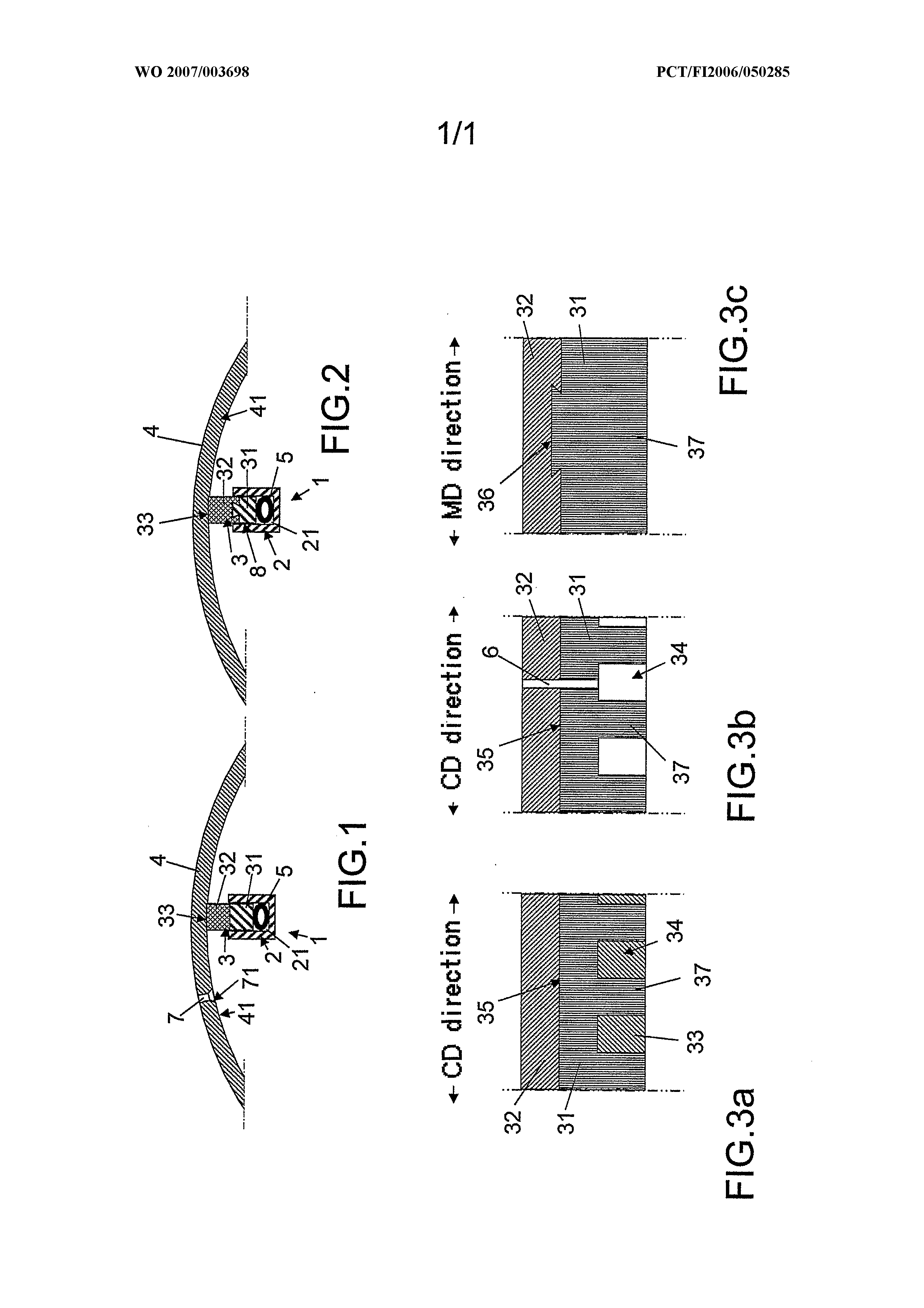
preferred and related to a sealing strip of a suction roll of a paper machine by reference to the attached patent drawing, in which FIG 1 shows a first embodiment of the present invention, FIG 2 shows a second embodiment of the present invention, FIG 3a shows one embodiment of a strip element according to the invention, FIG 3 b shows a second embodiment of a strip element according to the invention, and FIG 3c shows a third embodiment of a strip element according to the present invention. In order to provide a suction effect in a suction roll, at least one pair of sealing strips 1 are arranged inside the suction roll substantially in the direction of the axle of the suction roll and in the rotation direction of the suction roll at an interval from each other, which sealing strips 1 form between them a suction zone of the suction roll. If, for some reason, the contact of the sealing strip with a mantel 4 of the suction roll, or a facing surface 41 , is weakened locally or due to wearing, the opportunities to maintain underpressure in the suction zone are also correspondingly weakened. The weakening suction effect is attempted to be compensated by increasing suction power. However, this does not always succeed but premature maintenance must be resorted to or the paper web must be processed in a humidity state for which the part or parts of the paper machine after the suction roll have not been designed. Referring to FIG 1, which shows a cross-sectional profile of a strip element 3 fitted to a holder 2 of a sealing strip 1 according to a first embodiment of the invention, when the sealing strip is against a surface of a mantel 4 of a suction roll, which surface functions as a facing surface 41 of the sealing strip when a loading means 5 loads the strip element in the holder so that the strip element is pressed against the facing surface. Referring to FIG 2, which shows a cross-sectional profile of a strip element 3 of a sealing strip 1 according to a second embodiment fitted to a holder 2 when the sealing strip is against a surface of a mantel 4 of a suction roll, which surface functions as a facing surface 41 of the sealing strip when a loading means 5 loads the strip element in the holder so that the strip element is pressed against the facing surface.
As can be seen in FIG 1 and FIG 2, the sealing strip 1 is fitted to a profile element 2. The profile element is preferably a longitudinal U profile open in the direction of the facing surface 41. The U profile functions as a holder of the strip element 3 so that the strip element fitted to the holder, which strip element is two-layered in a transverse direction with respect to its length, protrudes from the U profile and, when loaded by the loading means 5, is against the facing surface, which moves when the suction roll rotates in a transverse direction with respect to the length of the strip element. The loading means 5 may be, as illustrated in FIG 1 and FIG 2, a hose means to be filled with a pressure medium, for example, and thereby expanding, which hose means, when expanded, is shaped in the form of a round hose by its cross-sectional profile, whereby the loading means pushes the strip element 3 outwards from the holder against the facing surface 41. In order to provide the desired functionality, especially a sealing effect, and to maintain the desired permanent contact between the sealing strip 1 and the facing surface 41, a first layer 31 of the strip element 3 is of a first material which is an easily shaping and/or adjusting material, which can be selected fairly freely for its purpose. It is preferable to manufacture the first layer, which is typically the layer inside the holder 2, from a material that enables bending and/or shaping of the strip means against the facing surface. Some suitable materials include plastics and rubbers and fibre-reinforced composites, for example. From the point of view of the material choices for the material layers of the sealing strip 1, it is essential that a second layer 32 of the strip element or at least its free edge 33, which, at least when the strip element is loaded, is against the facing surface 41, is of a second material. The material of the second layer is most suitably a wear resistant and harder or at least stiffer material than the material of the first layer. Thereby the desired functionality can be achieved and the loading of the strip element against the facing surface can be selected so that the strip element or its edge does not bend in the direction of the movement of the facing surface. In addition, the friction between the edge of the strip element and its facing surface and the wearing of the facing surface
of the edge of the strip element can be minimised. As suitable materials for the second layer 32 of the strip element 3 or at least for the free edge 33 of the strip element can be selected a carbon fibre material or a corresponding wear resistant and stiff composite material. The strip element can be manufactured from such a material in advance in a desired length and/or a desired profile shape by mould casting, continuous casting, extrusion, pultrusion and/or thermal hardening. A strip element manufactured from traditional materials may be manufactured by first cutting an element blank of a desired length from a strip element blank and after that machining the cut element blank into a desired profile shape. However, it is not typical of the present invention, especially when the strip element is of a carbon fibre material or a corresponding composite material, that first an element blank of a desired length would be produced by cutting, which would then be post-machined into a desired profile. In contrast, it is more typical of the present invention according to an embodiment considered preferred that, in order to form a strip means 1 of a desired length, several strip elements 3 manufactured in advance to a selected fixed size and profile are fitted to a fitting space in the holder 2 of the strip elements, which are joined and/or locked and/or connected consecutively end to end. Such manufacture of a strip element is typical especially when the strip elements are of carbon fibre or a corresponding composite material, whose post-machining is particularly problematic due to the hardness and wear resistance of the material. Since the friction between the facing surface 41 and the strip elements 3 causing abrasion generates heat, the fitting space 21 in the holder 2 is dimensioned to be longer than the aggregate length of the strip elements joined together or to be joined together, which allows unproblematic thermal lengthening of the strip elements in the holder. Referring to the embodiment in FIG 1 , in order for the strip elements 3 to be able to move in the holder 2, the second layer 32 of the strip element is immovably joined to the first layer 31 , for example by means of gluing or a tightening joint, such as a screw
joint. Thereby the strip element can only move in the fitting space in one piece with respect to the holder. Referring to the embodiment in FIG 2, in order for the layers 31, 32 of the strip elements 3 to be able to move with respect to each other and/or possibly the strip elements to be able to move in the fitting space 21 in one piece with respect to the holder 2, the second layer 32 of each strip element is joined movably to the first layer 31 by means of a mechanical joint, coupling and/or locking with a clearance, for example. Thereby the second layer of the strip element can move alone in the fitting space with respect to the holder and/or the first layer. One suitable joint for the purpose is a joint with facing surfaces corresponding to each other between the layers in the direction of the length of the strip element 3. FIG 2 illustrates a dovetail joint with a clearance. Referring to FIG 3a and FIG 3b, which diagrammatically show a cross-section of embodiments of a strip element 3 or a dewatering strip in the CD direction, and FIG 3c, which diagrammatically shows a cross-section of a third embodiment of a strip element 3 or a dewatering strip in the MD direction. In the embodiments in FlG 3a and FIG 3b a second layer 32 of a strip element has been immovably joined to a first layer 31 by gluing 35, for example, whereby the strip element can move in a holder so that the first layer and the second layer are essentially immovable with respect to each other. Alternatively, the second layer 32 of the strip element may be joined to the first layer 31 movably, by means of mechanical locking with a clearance, for example. The embodiment in FIG 3c shows as an example a form fit locking with a clearance and thus a dovetail joint 36 in the direction of the length of a strip element runs in the direction of the length of the strip element 3. Thereby a second layer 32 of the strip element 3 can move alone in a holder 2 with respect to a first layer 31. If a joint without a clearance or equipped with a tight fit is used in such a form fit locking, the joint functions like a fixed joint (cf. FIG 3a, for example), whereby the strip element can move in the holder so that the first layer and the second layer are essentially
immovable with respect to each other. According to the present invention, notches 34 which are essentially in the MD direction and which are separated from each other by unnotched projections 37 have been arranged in the edge inside the holder 2, opposite to the free edge 33 of the strip element 3 loaded towards the facing surface 41 in the direction of the length of the strip element, or the CD direction, at an interval from each other. Such notches may reduce the rigidity of the strip element and thus the notches may promote the adjustment and/or shaping of the strip element, which is loaded towards the facing surface 41, to the facing surface 41. The mutual relationships between the notches and the projections and the depth and interval of the notches may vary and they are selected according to the desired flexibility. The notches 34 may be filled with a flexible filler material 33, foam plastic, for example, or the notches may be left free of a filler material. Both solutions meet the requirement of an adjusting and/or shaping strip element. An additive can be channelled between the notches 34 and through the facing surface 41 of the suction roll and the sealing strip / strip element 3, or between the surfaces abrading against each other, in order to reduce friction and abrasion and to protect the facing surface inside the roll and to reduce the effect of the abrasion of the sealing strip or the strip element of the sealing strip. For the feeding of the additive the sealing strip or the strip element of the sealing strip may have a feeding channel or a feeding aggregate 6, which extends in the notched sealing strip / strip element 3 from the notch 34 or projection 37 between the facing surface 41 and the sealing strip / strip element 3. Suitable additives include suitable polymers, such as wax, a Teflon solution and various additives used in water hydraulics, for example. Besides or instead of notches it is also possible to apply local thinning and/or relieving of the strip element 3 in the CD direction and/or MD direction in order to improve the adjustment and/or shaping of the strip element 3. The strip element may be notched in the direction of its width (not shown in the figures). In this case the loading means may load the unnotched parts of the strip element in the holder 2, which delimit the notch and/or notches.
Therefore a structure of the strip element 3 has been provided which allows providing a strip element that adjusts corresponding to a facing surface that change in time and/or place. Thereby use of lower loading forces or loading pressures is enabled without dangers of air leakage. It can also be stated about such an adjusting strip element that • the height of the strip element 3 or at least that of its second layer 32 may be minimised, • part of the strip element 3 may be manufactured from a material whose modulus of elasticity is lower or the whole strip element is of a material with a lower modulus of elasticity, • the rigidity of the second layer 32 of the strip element 3 is otherwise lowered in the CD direction and/or the MD direction. It should be noted that it is important to ensure that the friction between the holder 2 and the strip element 3 is as low as possible so that the frictional force caused by the rotation of the suction roll 4 and the underpressure between the strip element and the holder would not interfere with the loading pressure of the strip element and/or the rotation of the suction roll. The one-sided lateral force caused by the frictional force of the facing surface 41 may decline the strip element 3 and thus cause an increase in friction. Friction may be reduced by a Teflon layer 8, for example, (cf. FIG 2) at the edges of the holder 2 or by pivoting (not shown in the figures) the strip element 3 at its input or output side to a pivot line, which is correspondingly at the input or output side of the strip. Thereby a sensitively moving strip element produces the desired result more securely with lower loading. By means of a sensitively moving sealing the minimisation of loading can be implemented better without a risk of leakage. In connection with reducing abrasion one should also search for such a limit pressure between the strip element 3 and the facing surface 41 of the suction roll below which harmful consequential phenomena no longer occur.
The heat due to friction generated from abrasion varies in time and place, which is a result from the fact that the contact to the facing surface 41 does not remain similar along the whole length of the strip element. This may lead to considerable local wearing, leaks and thus a need to increase the loading pressure on the strip element. According to the invention it is recommended, especially to ensure even loading of the strip element 3 of the sealing strip against the facing surface, that the strip element fitted to the sealing strip is adjusting under loading against the facing surface. With wearing the strip element 3 adjusting to the facing surface 41 evens out variations and enables the use of lower loading pressures without the sealing strip starting to leak. An adjusting strip element can be prepared for example by notching the strip from the underside at fixed intervals, by using wholly or partly a material with a lower modulus of elasticity, or by minimising the height of the strip. Since from the point of view of heat generation it is apparent that different sealing strip materials generate heat in different ways such a sealing material should be used whose heat generation is low and whose surface activating effect is slight. According to the invention the loading pressure on the strip element 3 of the sealing strip is set or adjusted to be as low as possible so that a sufficient sealing effect on the strips is still maintained. The adjustment can be made automatically controlled. This can be implemented for example so that the underpressure in the underpressure chamber UPC is followed and the loading of the strip element is kept at such a limit pressure that the sealing between the strip element and the facing surface 41 does not yet leak harmfully. The use of formed loading hoses 5 conferring a constant load makes the minimising of the loading pressure easier according to the invention. On the background of the present invention there is an attempt to significantly reduce the strength of the abrasion caused by the sealing strip, which abrasion may, when strong, cause fatigue of the material and/or activation of the surface. Thus abrasion may significantly reduce the service life of the mantel 4 of the suction roll. This attempt may be achieved by the suction roll according to the invention so that optionally the elimination of the effects of abrasion or at least their significant reduction is implemented by surface treatments of the facing surface 41, good feeding
of a lubricant between the strip element 3 and the facing surface, or the feeding of a protective additive on the facing surface of the strip element. The surface treatment of the facing surface may be implemented by means of grain blasting, a thermal injection coating, a chemical or electro-chemical precipitation coating and/or a polymer-based coating. It is emphasised that the above-mentioned surface treatments are only examples and that other treatments and/or coatings protecting the surface known as such fall within the scope of the invention and they may be applied in order to achieve the desired purpose. The grain blasting of the inner surface of the mantel 4 of the suction roll or the facing surface 41 of the strip element 3 of the sealing strip is performed according to the invention preferably by using ceramic-based sand, glass balls or a material containing a corresponding hard grain-like substance, for example, in order to cause compression stresses on the inner surface of the mantel 4, which impedes or prevents the start of fatigue cracks. If only grain blasting is used in the surface treatment of the facing surface 41 it is recommended that the grain blasted facing surface is ground lightly to grind off any peaks on the surface. The thermal injection coating of the inner surface of the mantel 4 of the suction roll or the facing surface 41 of the strip element 3 of the sealing strip is applied according to the invention preferably by means of a metal coating, a metal ceramic coating or a ceramic coating. The thermal injection coating thus provided is preferably a WCCo coating, a chromium oxide coating or a combination coating of the release type. The prepared surface of such a thermal injection coating may be provided by the grain blasting explained above. The chemical or electro-chemical precipitation coating of the inner surface of the mantel 4 of the suction roll or the facing surface 41 of the strip element 3 of the sealing strip is applied according to the invention preferably as a brushing coating, more preferably by means of nickel plating, chromium plating, etc.
The polymer-based coating of the inner surface of the mantel 4 of the suction roll or the facing surface 41 of the strip element 3 of the sealing strip is applied according to the invention preferably by means of epoxidisation, teflonisation, etc. In addition, the wear resistance of the coating of the inner surface of the mantel 4 of the suction roll or the facing surface 41 of the strip element 3 of the sealing strip may be improved according to the invention by using a filler along with the coating. Preferable fillers include different oxides, carbides and/or metal particles, for example. In the background of the present invention there is an attempt to significantly reduce the strength of the abrasion caused by the sealing strip, which abrasion may, when strong, cause fatigue of the material and/or activation of the surface. Thus abrasion may significantly reduce the service life of the mantel 4 of the suction roll. This attempt can be achieved by the suction roll according to the invention so that an additive or lubricant is fed between the strip element 3 of the sealing strip and its facing surface 41, which abrade against each other. Thereby the additive or lubricant reduces the friction and the abrasive loading between the strip element and its facing surface and protects the facing surface of the strip element inside the roll, which significantly reduces the abrasive effect of the strip element on the inner surface of the mantel of the suction roll. According to the invention, the additive or lubricant may be fed together with lubricating water, whereby the lubricant or additive enters together with the mantel 4 of the rotating suction roll between the strip element 3 and its facing surface 41, or through the feeding channels 6 in the strip element, whereby the lubricant or additive enters directly through the feeding channel between the strip element 3 and the facing surface 41. Suitable lubricants or additives according to the invention include polymers, such as waxes, Teflon solutions or different additives for water hydraulics known as such, for example. In the background of the invention there is an attempt to significantly reduce the strength of the abrasion caused by the sealing strip, which abrasion may, when strong,
cause fatigue of the material and/or activation of the surface. Thus abrasion may significantly reduce the service life of the mantel 4 of the suction roll. This attempt may be achieved by the suction roll according to the invention so that, in order to reduce the effects of the abrasion of the strip element 3 of the sealing strip, at least part of suction holes 7 in a wall of the mantel 4 have been broached or chamfered to be cone-shaped or rounded on the side of the facing surface inside the mantel. Such broaching of the suction holes 7 in the mantel of the suction roll, which rotates round its geometrical longitudinal axle, may alone or together with the surface treatment of the facing surface of the strip element of the sealing strip inside the mantel 4 of the suction roll and/or together with the feeding of a lubricant or an additive may decisively reduce the abrasive loading of the sealing strip on the mantel of the suction roll, which is apt to significantly increase the service life of the suction roll. In the background of the invention there is an attempt to significantly reduce the strength of the abrasion caused by the sealing strip, which abrasion may, when strong, cause fatigue of the material and/or activation of the surface. Thus abrasion may significantly reduce the service life of the mantel 4 of the suction roll. This attempt may be achieved by an arrangement according to the invention so that, in order to reduce the effect of the abrasion between the strip element and the facing surface, loading pressure is adjusted or set to such a limit pressure at which a sufficient sealing effect is still maintained or harmful leakage does not occur. According to the invention it is desirable that at the limit pressure of the strip element the setting or adjustment of the loading pressure is as low as possible so that a sufficient sealing effect is still maintained and the harmful consequential phenomena caused by abrasion can no longer occur. The loading pressure between the strip element 3 of the sealing strip and its facing surface 41 is essentially even throughout a contact area of the strip element and the facing surface. In addition, according to the invention the strip element is essentially shaping corresponding to the shape of the facing surface. The shaping of the strip element to the facing surface may be ensured by a strip element, for example, which has notches 34 at an interval from each other in
the long free edge 33 opposite to the sealing edge. According to the invention the setting or adjustment of the loading pressure of the strip element 3 is automatically controlled. This can be implemented for example so that the setting or adjustment of the loading pressure of the strip element follows the underpressure in the fitting space 21 of the strip element or the underpressure chamber UPC and keeps the loading of the strip element at such a limit pressure at which the sealing between the strip element and the facing surface 41 does not yet leak harmfully. A preferable loading means 5 for loading the strip element is a hose means to be filled with a loading medium or a loading hose, the use of which may also make the optimisation and/or minimisation of the loading pressure easier. In order to significantly reduce the basic problem in the background of the invention, or the strength of the abrasion caused by the strip element 3 of the sealing strip, which abrasion may, when strong, cause fatigue of the material and/or activation of the surface. Thus abrasion may significantly reduce the service life of the mantel 4 of the suction roll. This problem may be solved by a method according to the invention for improving the duration of the mantel of the suction roll of the material web machine when the sealing strip or its strip element 3 is loaded in the holder 2 of the strip element against the inner surface of the perforated mantel 4 of the rotating suction roll, which inner surface functions as the facing surface 41 of the strip element, so that, in order to reduce the effect of the abrasion between the strip element and the facing surface, loading pressure is adjusted or set to such a limit pressure at which a sufficient sealing effect is still maintained or harmful leakage does not occur. In this case it is recommended according to the invention that the loading pressure between the strip element 3 and the facing surface 41 is kept substantially even in the contact area of the strip element and the facing surface. In order to keep the loading pressure evenly constant substantially along the whole length of the strip element 3, a strip element ensured to shape according to the facing surface 41 is used. A shaping strip element can be formed by a strip element equipped with notches 34 at its free edge 33, for example. The invention has been described above only by means of examples. Naturally, this
does not limit the invention to concern only such single example cases, but the scope of the invention is defined by the claims attached. So it must also be separately emphasised that the strip means according to the invention may be used not only for sealing purposes in the suction roll but for different dewatering purposes of the surface of the roll and also for purposes of cleaning the surface of the roll.
A strip means for a material web machine, which strip means (2, 3) may be a sealing strip of a suction roll (4), which sealing strip includes a longitudinal strip element (3) and a longitudinal holder (2) of the strip element shaped as a U profile open in the direction of a facing surface (41). The strip element, which is two-layered in a transverse direction with respect to its length, protrudes from the holder and, at least when loaded, is against the facing surface, which moves substantially in a transverse direction with respect to the length of the strip element. A first layer (31) of the strip element is of an easily adjusting material and a second layer (34) of the strip element is of a stiffer material in the loading direction than the first layer. In this way the loading of the strip element in the holder can be selected so that the strip element or its edge does not substantially bend in the direction of the movement of the facing surface. The invention also relates to an improved suction roll for a material web machine for improving the duration of the suction roll. A strip element is against a facing surface inside a perforated (7) mantel of the suction roll when a loading means (5) loads the strip element in a holder. In particular, in order to reduce the effects of the abrasion of the strip element, optionally: an inner surface of the mantel is surface treated by means of grain blasting, a thermal injection coating, a chemical or electro¬ chemical precipitation coating and/or a polymer-based coating; and/or a lubricant or additive is fed between surfaces abrading against each other; and/or at least part of suction holes in a wall of the mantel are broached (71 ) at the side of the facing surface inside the mantel. In addition, the invention relates to an arrangement for improving the duration of a suction roll. A strip element is against a facing surface inside a perforated mantel of the suction roll when a loading means loads it in a holder against the facing surface. In particular, the loading pressure of the strip element has been adjusted to a limit pressure at which a sufficient sealing effect is still maintained or harmful leakage does not occur. Moreover, the invention relates to a method for improving the duration of a suction roll when a strip element is loaded in a holder of the strip element against an inner surface of a perforated mantel of the suction roll. In particular, in order to reduce the effect of the abrasion between the strip element and its facing surface, loading pressure is adjusted to a limit pressure at which a sufficient AMENDED CLAIMS received by the International Bureau on 07 November 2006 (07.11.2006) L A strip means for a material web machine, which strip means may be a scaling strip S intended for sealing a suction roll and/or a dewatering strip intended for removing water from the surface of the roll, for example, which strip means (1) includes a longitudinal strip clement (3) and a longitudinal strip profile (2), which is a U profile open in the direction of a facing surface, for example, and which functions as a holder of the strip element so that the strip element fitted to the holder, which strip element is 0 in a transverse direction with respect to its length and substantially two-layered in its loading direction, protrudes from the profile element and, at least when loaded, is against a facing surface (41 ), which moves in a substantially transverse direction with respect to the length of the strip dement, characterised in that a first layer (31) of the strip element (3) is of a first material, which is an easily shaping material, that a 5 second layer (32) of the strip element, which joins the first layer and which has a free edge (33), which, at least when the strip element is loaded, is against the facing surface (41), is of a second material, which is a stiffer material in the loading direction of the strip element than the material of the first layer, and that the strip element or its edge cannot substantially bend in the direction of the movement of the facing surface. 2. A strip means according to the claim 1, characterised in that the first layer (31) is substantially the layer inside the holder (2) and that the first material is easily shaping and/or adjusting when the strip clement (3) is loaded from the holder towards the facing surface (41) and a material that may be fairly freely selected, such as plastic and/or rubber or other such fibre-reinforced shaping and/or adjusting material, for example, which can be fairly freely selected. 3. A strip means according to flic claim 1 and/or 2, characterised in lhat the materia] of the second layer (32) of the strip element (3) is of a hard stiff composite material, carbon fibre material, etc., for example, in which case each strip element (3) is manufactured in advance in a desired length and a desired profile shape.
4. Λ strip means according to the cJaim 3, characterised in tbat, in order to form a strip means (1) or a desired length, several strip elements (3) have been joined and/or locked and/or connected consecutively end to end. 5. A strip means according to any one of the preceding claims, characterised in that a fitting space (21 ) of the strip elementø (3) in the holder (2) is longer that the aggregate length of the strip elements joined together or to be joined together to allow thermal lengthening of the strip elements in the holder. 6. A strip means according to any one of the preceding claims, characterised in tlmt thc second layer (32) of me strip element (3) is joined to the first layer (31 ) immovably, for example by means oi' gluing or a tightening joint or a form fit without a clearance, whereby the strip clement (3) may move in the holder (2) with respect Io the holder. 7. A strip means according to any one of the claims 1 to 5S characterised in-that the second layer (32) of the strip element (3) is joined to the first layer (31) movably by means of a mechanical connection or locking with a clearance, for example, whereby the second layer of the strip clement may move alone with respect to the holder (2) and/or the first layer. 8. A strip means according to any one of the preceding claims, characterised in that, in order to improve the adjustment and/or shaping of the strip element, notches (34) which are Substantially in a transverse direction with respect to the strip element and which arc separated from each other by unnotcbed projections (37) in said notched edge have been arranged in an edge which remains inside the holder (2), opposite Io the free edge (33) of the strip element loaded towards the facing surface (41). 9. Λ strip means according to the claim 8, characterised in that the notches (34) have optionally been filled with a flexible filler material (33), foam plastic, for example. 10. A strip means according to any one of the preceding claims, characterised in that,
in order to improve the adjustment and/or shaping of the strip element, the strip element has been locally thinned and/or relieved. 11. A strip means according to any one of the preceding claims, characterised in that the characteristics of the material of the first layer (31) of the strip element (3) optionally include the following: the first material layer extends continuously along the whole length of the strip means, the first material layer is flexible in the loading direction of the strip means, whereby the strip means easily adjusts and/or shapes to (he lacing surface (41) and it is enabled that an evetx contact is formed between the strip means and its facing surface and local pressure peaks or ruction peaks cannot be generated, by the choice of material for the first material layer (cf. plastic/rubber, for example) and/or forming, which includes notching and relief and thinning, for example, different flexibilities may be provided in the strip element, as necessary. 12. A strip means according to any of the preceding claims, characterised in that the desirable requirements for the material of the second layer (32) of the strip element (3) optionally include: - low friction, low heat generation, good wear resistance, endurance of bad lubrication or dry run, is very thin in the loading directiont - may be formed of pieces, in which case the first layer (31) is continuous, has high rigidity, in which case the second layer is only a part of the strip element so that the second layer does not stiffen the whole strip element. 13. A strip means according to any one of the preceding claims, characterised in that, in order to reduce friction, there is a material layer (38) of Teflon or a comparable substance, for example, at contact surfaces at the edges of the holder (2) of the strip element (3), whereby a sensitively moving strip clement more securely produces the
desired result with lower loading and the minimisation of loading may be implemented better without the risk ofleakage. 14. A strip means according to any one of the claims 1 to 13, characterised in that the strip element (3) of the sealing strip is pivoted in the holder (2) at its input or output side, whereby a sensitively moving atrip element more securely produces the desired result with lower loading and the minimisation of loading may be implemented better without a risk of leakage. 15. A strip means according to any one of the preceding claims to be applied with an improved suction roll for a material web machine for improving the duration of the suction roll, in which a sealing strip or a strip element (3) of the sealing strip is against an inner surface of a perforated (7) mantel (4) of the suction roll, which inner surface functions as a facing surface (41 ) when a loading means (5) loads the strip clement in a holder (2) against the facing surface, characterised m that, in order to reduce the effects of the abrasion of the scaling strip or the strip element (3) of the sealing strip, the inner surface of the mantel (4), which functions as the facing surface (41 ) of the sealing strip or the strip element (3) of the scaling strip, is surface treated or coated. 16. A strip means according to the claim 15, characterised in that the inner surface of the mantel is surface treated and/or coated preferably by means of grain blasting, a thermal injection coating, a chemical or electro-chemical precipitation coating and/or a polymer-based coating. 17. A strip means according to the claim 15 and/or 16, characterised in that, in oτdeτ to generate compression stresses on the inner surface of the mantel (4), which impede or prevent the start of fatigue cracks, grain blasting has been performed by using ceramic-based sand, glass balls or a material containing a comparable hard grain-like substance, for example. 18. A strip means according to the claim 16, characterised in that the thermal injection coaling has been applied by means of a metal coating, metal ceramic coating
or a ceramic coating, for example 19. Λ strip meant) according to the claim IS, characterised in that the thermal injection coaling js preferably a WCCo coating, a chromium oxide coating or a combination coating of the release type. 20. A strip means according to the claim 15, characterised in that the chemical or cleCtrO-chcmical precipitation coating has been applied preferably as a brushing coating, more preferably by means of nickel plating, chromium plating, etc, 21. A strip means according to the claim 15, characterised in that the polymer-based coating has been applied by means of epoxidisation, tcilonisation, etc, 22. A strip means according to the claim 2 K characterised in that, in order to improve the wear resistance of the coaling of the facing surface, the coating may include a filler, which preferably includes oxides, carbides and/or metal particles. 23. A strip means according to any one of the preceding claims, characterised in that the grain blasting functions as an adhesion for coatings, preferably a thermal injection. 24. A strip means according to the claim 23, characterised in that when using grain blasting alone the facing surface (41) is ground lightly in order to grind off any peaks on the surface of the facing surface. 25, A strip means according to any one of the claims 1 to 13 to be applied with an improved suction roll for a material web machine for improving the duration of the suction roll, in which a sealing strip or a strip clement (3) of the seating strip is against an inner surface of a perforated (7) mantel (4) of the suction roll, which inner surface functions as a facing surface (41) when a loading means (5) loads the strip element in a holder (2) against the facing surface, characterised in that an additive is fed between abrasive surfaces, or between the facing surface (41 ) and the sealing strip or the strip element (3) of the scaling strip, in order to reduce friction and abrasion and to
protect tlio facing surface inside the roll and to reduce the effect of the abrasion of the sealing strip or the strip clement (3) of the sealing strip. 26. A strip means accoiding to the claim 25, characterised in that the additive is fed with lubricating water or through feeding channels (6) in the sealing strip / strip element (3). 27. A strip means according to the claim 25 and/or 26. characterised in that the additive is a suitable polymer, such as wax, a Teflon solution or an additive for water hydraulics, known as such. 28. A strip means according to any one of the claims 1 to 13 to be applied with an improved suction roll for a material web machine for improving the duration of the suction roll, in which a sealing strip or a strip clement (3) of the sealing strip is against an inner surface of a perforated (7) mantel (4) of the suction roll, which inner surface functions as a facing surface (41) when a loading means (5) loads the strip element in a holder (2) against the facing surface, characterised in that, in order to reduce the effects of the abrasion of me strip element (3) of the sealing strip, at least part of suction holes (7) in a wall of the mantel (4) have been broached or chamfered to be cone-shaped or rounded at the side of the facing surface inside the mantel. 29. A strip means according to any one of the preceding claims 15 IO 28, characterised in that, in order to reduce the abrasion caused by the scaling strip or the strip clement of the sealing strip, an optional surface treatment of the mantel (4) of the suction roll has been implemented together with the feeding of the additive and/or broachiπgs or roundings of the suction holes (7) in the mantel. 30. Λ strip means according Io any one of the preceding claims to be applied with an arrangement in a suction roll for improving the duration of the suction roll wh.cn a sealing strip or a strip element (3) of flic sealing strip is against an inner surface of a perforated mantel (4) of the suction roll, which inner surface functions as a facing surface (41) when a loading means (5) loads the strip clement in a holder (2) against
the facing surface, characterised in that, in order to reduce the effect of the abrasion betweenlhc strip clement (3) and the facing surface (41), loading pressure is adjusted or set to such a limit pressure at which a sufficient scaling effect is still maintained or harmful leakage does not occur. 3 L A slip means according to the claim 3O5 characterised in that at the limit pressure of the strip element (3) the setting or adjustment of the loading pressure is as low as possible so that a sufficient sealing effect is still maintained and the harmful consequential phenomena caused by abrasion can no longer occur. 32. A strip means according to the claim 30 and/or 31 , characterised in that the loading pressure between the strip clement (3) and the facing surface (41) is essentially even in a contact area of the atrip clement and the lacing surface. 33. A strip means according to any one of the preceding claims, characterised in that the setting or adjustment of the loading pressure of the strip clement (3) may be automatically controlled. 34. A strip means according to the claim 33, characterised in that the selling or adjustment of the loading pressure of the strip element (3) follows the underpressure in a fitting space (2J) of the strip clement or an underpressure chamber (UPC) and keeps the loading on the strip element at such a limit pressure at which the scaling between the strip element and the facing surface (41) does not yet leak harmfully. 35, Λ strip means according to the claim 34, characterised in that the loading means (5) is a hose means to he filled with a loading medium or a loading hose, the use of which may make the optimisation and/or minimisation of the loading pressure easier. 36. A method to utilize a strip means according to any one of the preceding claims 1 to 35 for improving the duration of a suction roll of a material web machine when the sealing strip or the strip element (3) of the strip means is loaded in a holder (2) of the strip element against an inner surface of a perforated mantel (4) of the rotating suction
Toll, which inner surface functions as a facing surface (41) of the strip clement, characterised in that, in order to reduce the effect of the abrasion between the strip element (3) and the facing surface (41), loading pressure is adjusted or set to such a limit pressure at which a sufficient sealing effect is still maintained or harmful leakage does not occur such that the loading pressure between the strip element (3) and the faciog surface (41) is kept substantially even in a contact area of the strip clement and the facing surface. 37. Λ method according to the claim 36, characterised in that, in order to keep the loading pressure constant substantially along the whole length of the strip element (3), it is preferable that a strip element ensured to be shaping according to the facing surface (41), such as a strip element equipped with notches (34) at its free edge (33).