Weichenstellkraftbolzen mit asymmetrischer krafteinleitung
The invention refers to a mechanism for the measurement of the switch adjusting force with rail switches with a sensor and a sensitive contact designed connected with the sensor as deformation bodies, which are applicable into a joint in the Weichenantrieb, whereby the sensor is designed as electromechanical sensor and is arranged outside of the Kraftangriffes on the sensitive contacts in a head connected with the sensitive contact.
A mechanism of the kind initially specified is from the ATPS… (A 920/93) become known. The well-known Weichenstellkraft_messer consists of a slit steel body as deformation body, which carries a sensor. The well-known switch adjusting force measurer serves for measuring the forces arising between the Weichenantrieb and the switch, whereby it unimportant whether these forces of the Weichenantrieb work on the Weichenzungen or as fixed strength with feather/spring rail tongues or as rear-end collision strength against the holding strength or against the rear-end collision resistance of the Weichenantriebes. The sensitive contact becomes this purpose in place of a switch tie bolt into an universal joint and/or.
inserted into a fourwheel joint, whereby by slitting the steel body bending bars are trained. During the well-known mechanism bulge-like Verdickungen are intended at the exterior, which serve the attack of the forces in each case. From at-PS… (A 920/93) nascent Ausbi admits! - dung consisted of that the sensor is designed as electromechanical sensor and is arranged outside of the Kraftangriffes on the sensitive contacts in a head connected with the sensitive contact. Thereby that within the sensitive contact no parts of the measuring sensor were arranged, which are suspended due to the length of the Meßbolzehs oscillations, but electromechanical sensors were arranged outside of the Kraftangriffes in the head of the sensitive contact, became training created, which could exhibit an accordingly broad head, which using and taking the pin from the respective measuring position facilitated. Into the head of a such sensitive contact according to mechanically protected measuring sensor, as it can be taken for example the US-PS 4,530,245, could be inserted in simple way. In order to guarantee also with thick-walled training of the pin head and with appropriate stable high-grade steel training of the sensitive contact and the head an accordingly good ductility and thus an accordingly large signal, the older training was met in such a way that the head for the admission of the measuring sensor is slit trained transverse to the axle of the pin.
In particularly favourable way the well-known training could be in such a way met also with more substantial and with it stoßund fall-secured training of the sensitive contact with the measuring head that the head exhibits two slots shifted in axial direction, whereby despite the stable and training insusceptible to shock a measurement is guaranteed.
So shockproof and simple training of the sensitive contact can with advantage also in the rough railway company directly by connection to PC-bzw. Laptop to a complex evaluation mechanism to be hooked up, whereby with advantage the training was met in such a way that the sensor by a signal amplifier and a similar to/digital transducer is connected to a serial interface with a standard interface, in particular with a computer, with a memory and an announcement.
The invention aims now off to train the before-well-known training further in such a way that also with small adjusting forces and according to high Stabi1 ität the sensitive contact an accordingly sensitive measurement with high reproductibility succeeds. For the solution of this task, the Einrichtnng according to invention, on the basis of a mechanism of the kind initially specified essentially of consists that the sensitive contact at its coat three circular collections for the force application, extending in circumferential direction, exhibits itself, which are outside of the centre plane of the joint implemented by the Gelenkachse in different axial distance from each other arranged and cooperate also against each other tiltable parts of the joint. Thus that the circular collections and/or ribs are beabstandet implemented in according to invention suggested the way in axial direction, succeeds to introduce it the adjusting forces so far RK 000,523 UI eccentrically in the sensitive contacts that a reinforcement of the mechanical deformation and thus the measuring signal resulting in according to the Hebelgesetz succeeds itself. Altogether by the off center force admission also with extremely small adjusting forces already a precise measured value is obtained and the sensitivity of the well-known mechanism is thus increased substantially, without impairing the working reliability and the stability of the sensitive contact.
The training according to invention is in such a way trained further with advantage that an axial distance of the circular collections is to each other larger, than those width a part of the joint of the forming coupling rod toward the drag axis of the joint measured, with which is guaranteed that the maximally conceivable distance for an off center force application can be used and an appropriate mechanical measuring signal reinforcement can be obtained.
The desired measure of off center force application for the purpose of the mechanical power gain is guaranteed with advantage thereby that those are to each other arranged the sensor and/or the head neighbouring circular collections in an axial distance, which is smaller than the axial distance between the middle and that the head turned away third circular collection, whereby the sensor is arranged for first collection favourably in the head directly neighbouring.
Thus it is guaranteed that the force application of the first collection results in a safe deformation of the sensitive contact of the clamping place of the sensor. In addition the training can so meet werde_n that the sensitive contact exhibits an axial drilling for a cable entry. In particular a such axial drilling for a cable entry makes it possible to move protected downward now the cable entry, and to the end of the sensitive contact a simple plug for large Kabe! - to arrange connections. The mechanically substantially less resistant interwirings and plug can be arranged in this way protected at the lower surface and it succeed an as far as possible complete packaging of the measuring sensor to lying exposed Oberbzw. Exterior, whereby the Be4 impulse security can be increased. The training is so met hiebei with advantage that an anti-twist plate for the sensitive contact is designed as the sensor outside sealing embracing cover.
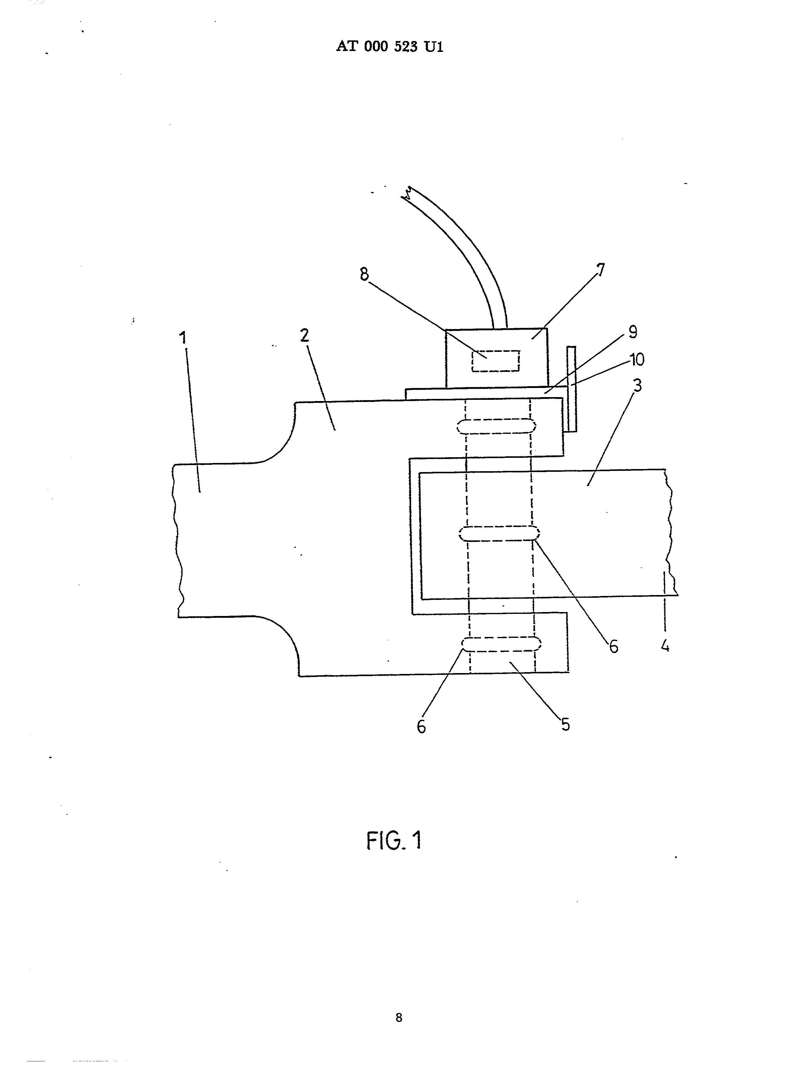
The invention is more near described in the following on the basis a comparison of the well-known training with the further training according to invention. In this show: Fig.l a schematic scrap view by a joint with assigned sensitive contact after the state of the art; Fig.2 a perspective side view of the well-known sensitive contact and Fig.3 a partial cut by the training according to invention.
In Fig.l the end of a tie bar is 1 with a gift! piece of 2 evidently, into which a bearing centre of a coupling rod 4 dives. The connection between the bearing centre 3 and the fork 2 effected by means of a sensitive contact 5, which rippenförmige collections 6 suggested schematically at its extent exhibit, which kraftschiüssig in each case in the appropriate recesses of the fork 2 and/or the bearing centre 3 attack. At the free end of the pin 5 a head 7 is arranged, in which an electromechanical sensor 8 is arranged.
The head 7 exhibits turned end attack Schult œ an r for a plattenförmigen bar 9 of a distance piece i0 at its exterior of the fork 2 and is accordingly held at the distance piece I0. The distance piece i0 embraces hiebei also transverse to the plattenförmigen bar 9 running parts the claw and/or the fork 2.
In Fig.2 the sensitive contact 5 is again evident in the detail. At the exterior into the bearing centre of the diving in and the fork 2 interspersing Meßboizen again circular collections 6 are intended, which serve the force application.
The widened head 7 is trained with slots [...] and contains in its cavity the eiektromechanischen measuring sensor 8.
The electrical inlet is accordingly course-secured suggested with 12.
In Fig.3 now the training according to invention is evident, whereby the circular collections and/or ribs 6 in a distance A and b are from each other arranged and are arranged the three circular collections 6 outside of the longitudinal centre plane 13, the joint in each case, which by the drag axis 14 of the joint is interspersed. The measuring sensor 8 is neighbouring in the head 7 arranged the first circular collection 6. The distance C first, the sensor 8 neighbouring circular collection 6 of the centre plane 13 is evidently larger hiebei than the distance b, between which the measuring head 7 neighbouring first two circular collections 6. the middle circular collection 6 of the sensitive contact 5, which is in breaking through the coupling rod 4, ninunt forces off center up, whereas with the well-known training the force admission takes place in the Längsmlttelebene 13. This misalignment of the middle circular collection 6 toward to the sensor 8 from the longitudinal centre plane 13 out toward to the pressure capsule 8 leads to the appropriate mechanical reinforcement of the deformation and thus the reinforcement of the available electrical measured value.
The cable 12 is with the Aubildung after Fig.3 by one axia! e drilling of the sensitive contact 5 passed through and ends into a plug 15, which can be arranged protected at the lower surface.
In order to protect and encase the exterior better from environmental influences, a cover 16 is intended, which is fixed with screws 17 at the fork 2. This cover 16 embraces the head 7 and thus the pressure capsule 8 sealing, whereby an appropriate anti-twist plate can take place at the same time here. The slot extending in longitudinal direction of the sensitive contact 5 is suggested with 18. The measuring device has an electromechanical sensor (8) coupled to a deformation element in the form of a measuring bolt (5) incorporated in a linkage of the points setting drive. The measuring bolt has 3 annular projections (6) at spaced points along its outer mantle and different distances from the centre plane (13) passing through the bolt axis (14), cooperating with relatively pivoted parts (2,4) of the linkage. The electromechanical sensor is incorporated in the head of the bolt, outside the force application range. I. Mechanism for the measurement of the switch adjusting force with rail switches with a sensor (8) and one with the sensor (8) connected sensitive contact trained as deformation bodies (5), which is applicable into a joint in the Weichenantrieb, whereby the sensor (8) as electromechanical sensor (8) is trained and outside of the Kraftangriffes on the sensitive contact (5) in eßnemmit the sensitive contact (5) connected head (7) arranged is characterized, by the fact that the sensitive contact (5) at its coat three itself circular collections extending in circumferential direction (6) for the force application exhibits, which outside of the centre plane (13) of the joint in different axial distance (A, b), interspersed by the Gelenkachse (14) from each other arranged are and also against each other tiltable parts (2,4) of the GeI of enkes cooperate. 2. Mechanism according to requirement! , by the fact characterized that an axial distance (A) of of the circular collections (6) is to each other larger, than the width a part of the joint of the forming coupling rod (4) measured toward the drag axis (14) of the joint. 3. Mechanism according to requirement 1 or 2, by characterized that those the sensor (8) and/or the head (7) neighbouring circular collections (6) in one axia! EN distance (B) are to each other arranged, which is smaller than the axial distance (A) between the middle and that the head turned away third circular collection (6). 4. Mechanism according to requirement i, 2 or 3, by the fact characterized that the sensor (8) in the head (7) directly neighbouring for first circular collection (6) is arranged.
Mechanism according to requirement 1 to 4, by characterized that the Meßbo! zen (5) an axial drilling (18) for a cable entry exhibits. 6. Mechanism according to requirement 1 to 5, by characterized that an anti-twist plate for the sensitive contact (5) as the sensor outside is sealing do-seizing cover (16) trained.