Method and device for the regulated feed of pulverized fuel to a flue stream gasifier
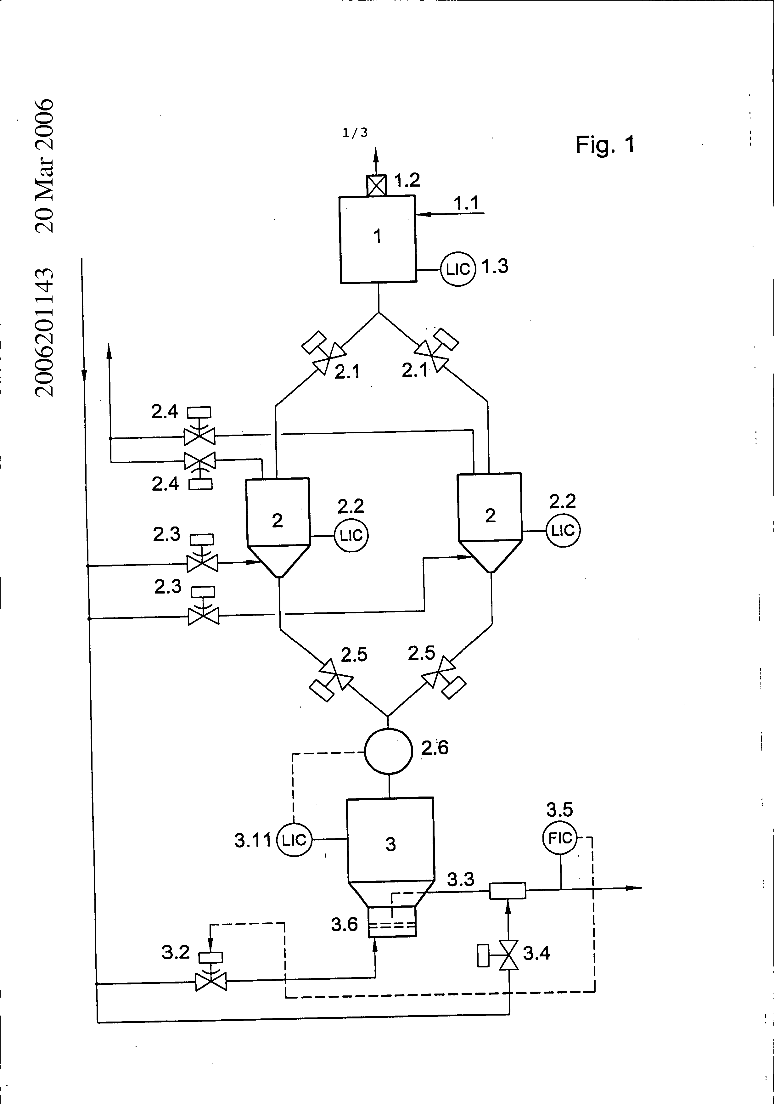
METHOD AND DEVICE FOR THE REGULATED FEED OF PULVERIZED FUEL TO A FLUE STREAM GASIFIER The following statement is a full description of this invention, including the best method of performing it known Method and device for the regulated feed of pulverized fuel to a flue stream gasifier TECHNICAL FIELD A method for constant infeed of pulverized fuel for pressurized gasification in the flue stream gasifier and a device for implementing the method is disclosed. BACKGROUND Pulverized fuel means coals of highly varied degrees of carbonization pulverized to the fineness of dust, such as bituminous coals and lignites, pulverized biomasses, cokes produced by thermal pretreatment including petroleum coke but also combustible residues and wastes from industry, domestic sources, and business trades that can be pulverized. Methods for pressurized gasification of dust-like fuels are known, in which the dust is fed through a pressurized sluice tank to a metering tank at gasification pressure, from which the pulverized fuel is fed through transport lines to the burner of the gasification reactor as a dust-carrier gas suspension with high loading densities between 250 and 450 kg/m 3. Flue stream gasifiers, gasifiers for dust-like fuels, and direct-feedtuyeres for blast furnaces are considered to be gasification reactors. Any reducing and neutral gases that are free of condensable constituents, for example such as water vapor, and whose content of free oxygen is < 6 vol.%, can be used as pressurizing gases for the pressurized sluices. DE-OS 26 54 662, CZ 254104, SU 170 2183 AI, and DE 2834208 C2 may be mentioned here. It is problematic with this technology that the amount of dust flowing per unit time has to be constant to be able to perform reliably in the necessary temperature range the process of gasification that occurs with an oxidizing medium containing free oxygen. In particular, the discontinuous loading of the metering tank from the pressurized sluices produces pressure fluctuations that have adverse effects on the pressure differential that serves as the driving force for conveying between the metering tank and the burners of the gasification reactor. SUMMARY According to a first aspect, there is provided a method for constant infeed of pulverized fuel under pressure into gasification reactors, comprising supplying the pulverized fuel alternately from an operational bunker through pressurized sluices to a metering tank, introducing a fluidizing gas through a turbulence plate into a bottom of the metering tank, to form a dense fluidized bed from the pulverized fuel and fluidizing gas, with a transport pipe immersed in the fluidized bed horizontally or vertically, feeding the fuel from the metering tank continuously through the transport pipe via a burner to a pressurized gasification reactor or other component, wherein fuel flow is measured in the transport pipe between the metering" tank and the gasification reactor; and separately from the fluidizing gas, feeding in auxiliary gas in the immediate vicinity of a transport pipe inlet into the metering tank below a level control of the pulverized fuel in an amount based on the value of the measured fuel flow obtained, wherein the amount of auxiliary gas fed in for a constant fuel flow is set by a control fitting. In one form an auxiliary gas may be introduced into the transport pipe to control pressure differentials between the metering tank and the component, for example the gasification reactor. To determine how much auxiliary gas can be introduced, the dust flow is measured in the transport pipe between the metering tank and the gasification reactor, and the necessary amount of auxiliary gas can then be set by instruments with reference to the value obtained. The stream of auxiliary gas can be preferably fed in near the inlet of each transport pipe. In one form another auxiliary gas inlet and outlet in the metering tank can be placed above the pulverized fuel bed. To do this, appropriate auxiliary gas lines and instruments are connected to the metering tank. In one form the flow velocity of the dust stream in the transport pipe can be regulated within the range of 2 to 8 m/s. It may be possible to introduce this technology of fluidized fuel infeed to other components also, for example to the tuyeres of a blast furnace, since reactions similar to those in a gasification reactor take place there. Important advantages of embodiments of the method consist in the facts that fluctuations of the pressure differential between metering tank and burners of the gasification reactor serving as the driving force for dust flow can be compensated by auxiliary gas infeeds to the transport lines and auxiliary gas inlets and outlets to and from the head space of the metering tank, and a constant dust flow rate can be assured. The transport pipe leading into the bottom of the metering tank can be positioned horizontally or vertically, from above or below. The infeed of auxiliary gas opens up the ability to maintain metering accuracy with fluctuations of the filled level. One or more transport pipes can be put in place for the dust stream. The pressure in the transport lines can be between 1 and 60 bar. The diameter of the transport lines can be varied between i0 and mm, depending on the transport output. The pulverized fuel can also be supplied to users other than a gasification reactor, for example the tuyeres of a blast furnace. Embodiments of the method and device are explained below with reference to an example and 3 Figures. It would be advantageous if at least some embodiments of the present disclosure provided a method with constant infeed of pulverized fuel, with which fluctuations of pressure differentials between metering tank and burners of the gasification reactor can be compensated. BRIEF DESCRIPTION OF THE DRAWINGS Notwithstanding any other forms which may fall within its scope, preferred forms of the method and device will now be described, by way of example only, with reference to the accompanying drawings in which: Fig. 1 Shows a diagram of one embodiment of the technology of dust metering under pressure; Fig. 2 Shows a schematic representation of one embodiment of a metering tank; and Fig. 3 Shows a schematic representation of one embodiment of an infeed of pulverized fuel to a pressurized gasification reactor. DETAILED DESCRIPTION OF SPECIFIC EMBODIMENTS Figure 1 shows a diagram of the technology for dust transport under pressure as it conforms to the state of the art. A flue stream gasifier (not shown) is operated under a pressure of 40 bar with an output of 500 MW. For this purpose, bituminous coal dust brought to a grain size of < 200 um is fed in at a rate of 90 Mg/h. The pulverized fuel is first fed to an operational bunker 1 through the transport line i.I by normal conveyance at low concentration, with the amount supplied being regulated in the level control 1.3. The transport gas is filtered in the filter 1.2 and released to the atmosphere or recompressed and again utilized for conveyance. Since the gasification reactor 4 is operated at 40 bar, the pulverized fuel has to be brought to this pressure. To do this, the pressure sluices 2 are loaded alternately with dust and pressurized with inert gas through the lines 2.3. Level regulators 2.2 prevent overfilling. The fittings 2.1 provide pressure-tight blocking toward the operational bunker i. When the level in the metering tank 3 has dropped to a minimum it is replenished from the pressurized sluices 2. The fittings 2.5 are opened to do this. After the pressurized sluices 2 are emptied, they are depressurized to atmospheric pressure through 2.4 and are again filled. Depending on the amount of dust to be transported, there can be one or more pressurized sluices 2. A pressurized star feeder 2.6 can be placed between the pressurized sluices 2 and themetering tank 3 to slow down the flow of dust. Replenishment into the metering tank 3 is regulated by the level control 3.11. The pressurized sluices 2 are replenished with pulverized fuel from the bunker 1 three times every hour, while the metering tank 3 is replenished 6 times every hour with 2 pressurized sluices, with 15 Mg being transported each time. The dust transport line 3.3 extends vertically into the bottom of the metering tank 3, in which a very dense fluidized bed 3.8 with densities up to 450 kg/m is produced through a turbulence plate 3.6 by feeding in fluidizing gas 3.2. When a pressure differential is applied between the metering tank 3 and the gasification reactor 4, the pulverized fuel-in-gas suspension controlled by 3.5 flows through the transport line 3.3 to the gasification reactor 4. According to Fig. 2, in this example three transport lines 3.3 are in operation, each with an output of 30 Mg per hour. To compensate for pressure fluctuations from the operation of the gasification reactor 4 and from the six-fold replenishment from the pressurized sluices 2, additional auxiliary gas is fed into the transport lines 3.3 through the lines 3.9, and additional auxiliary gas is fed to and discharged from the head space of the metering tank 3 through the lines 3.12 and 3.13. According to Fig. 3, the auxiliary gas can be fed in directly beyond the inlet of the transport line 3.3, but also at other places or at multiple places. The amount of dust flowing in the transport lines 3.3 is measured and regulated by 3.10 by controlling the amount of fluidizing gas with the control instrument 3.2, with the transport velocity in the pipes 3.3 being between 2 and 8 m/s and with the transport line diameter being 65 mm. The pulverized fuel flowing through thetransport line 3.3 is fed through the gasification burner 4.1 to the gasification reactor 4, and is reacted using a gasification medium containing free oxygen to produce a crude synthesis gas, which is sent through the line 5.1 by direct or indirect cooling in 5 to further treatment steps. A reference herein to a prior art document is not an admission that the document forms part of the common general knowledge in the art in Australia. In the claims which follow and in the preceding description of the method and device, except where the context requires otherwise due to express language or necessary implication, the word "comprise" or variations such as "comprises" or "comprising" is used in an inclusive sense, i.e. to specify the presence of the stated features but not to preclude the presence or addition of further features in various embodiments. of reference symbols used Supply bunker for coal dust Coal dust line Filter Level control Pressurized sluices Fittings for dust infeed Level control Control fittings for pressurization gas infeed Control fittings for depressurized gas release Fittings for dust infeed Pressurized star feeder Metering tank Level control Control fitting for fluidizing gas Transport line for dust stream Control fitting for auxiliary gas infeed Quantity control for dust stream Turbulence plate in the metering tank Pulverized fuel bed in the metering tank Fluidized bed zone in the metering tank Auxiliary gas infeed into the transport line Measurement and regulation of the dust stream Level control Auxiliary gas infeed Auxiliary gas discharge Gasification reactor Burner of the gasification reactor Crude gas cooling by quenching Crude gas discharge for gas purification This invention relates to a method for metering and feeding pulverized fuels under pressure into gasification reactors, with the pulverized fuel being supplied alternately from an o erational bunker through pressurized sluices to a metering tank, in the bottom of which a dense fluidized bed is formed by introducing fluidizing gas through a turbulence plate, with trans ort pipes immersed in the fluidized bed horizontally or vertically, by which the fluidized fuel is fed continuously through burners to a ressurized gasification reactor, which is distinguished by the fact that by feeding in auxiliary gas in the immediate vicinity of the transport line inlet into the metering tank or the transport lines, the ressure differential between the metering tank and the gasification reactor is controlled and is utilized as a control parameter for pulverized fuel transport, and a device for implementing the method. I. A method for constant infeed of pulverized fuel under pressure into gasification reactors, comprising:
supplying the pulverized fuel alternately from an operational bunker through pressurized sluices to a metering tank; introducing a fluidizing gas through a turbulence plate into a bottom of the metering tank, to form a dense fluidized bed from the pulverized fuel and fluidizing gas, with a transport pipe immersed in the fluidized bed horizontally or vertically, feeding the fuel from the metering tank continuously through the transport pipe via burner to a pressurized gasification reactor or other component, wherein fuel flow is measured in the transport pipe between the metering tank and the gasification reactor; and separately from the fluidizing gas, feeding in auxiliary gas in the immediate vicinity of a transport pipe inlet into the metering tank below a level control of the pulverized fuel in an amount based on the value of the measured fuel flow obtained, wherein the amount of auxiliary gas fed in for a constant fuel flow is set by a control fitting.
A method as claimed'in Claim i, wherein to further control the pressure differential between the metering tank and gasification reactor or other component, further auxiliary gas is also fed to and released from a head space of the metering tank.
A method as claimed in claims 1 or 2, wherein flow velocity of the fluidized fuel in the at least one transport pipe is in the range of 2 to 8 m/s.
A method as claimed in any one of the preceding claims, wherein the fluidized fuel is fed via the at least one transport pipe to said other component which comprises tuyeres of a blast furnace.
A device for constant infeed of pulverized fuel under pressure into gasification reactors, comprising:
a supply bunker; pressurized sluices connected to the supply bunker for feeding fluidizing gas; at least one transport line connected to the pressurized sluices; a metering tank connected to the pressurized sluices and the transport line via at least one transport line inlet; a turbulence plate for feeding in fluidizing gas to the metering tank; an infeed for feeding auxiliary gas into the metering tank separately from the fluidizing gas, said infeed being disposed beneath a level control of the pulverized fuel; and a gasification reactor connected to the transport line; means for measuring the amount of gas in the transport line between the metering tank and the gasification reactor; and a control fitting for setting a necessary amount of auxiliary gas based on the measured amount of gas in the transport line.
A device as claimed in claim 5, further comprising additional lines for further auxiliary gas in a head space of the metering tank.
A device as claimed in claims 5 or 6, further comprising a pressurized star wheel feeder between the pressurized sluice and the metering tank to smooth the filling process.
A device as claimed in any one of claims 5 to 7, wherein there are two or more pressurized sluices.
A device as claimed in any one of claims 5 to 8, wherein there are multiple transport lines between the metering tank and the gasification reactor.
A device as claimed in any one of claims 5 to 9, wherein a diameter of the transport lines is between i0 and 70 mm.
A device as claimed in any one of claims 5 to i0, further comprising lines for feeding auxiliary gas between the gasification reactor and the metering tank, said lines opening into the at least one transport line.
A method for metering and feeding pulverized fuels substantially as herein described with reference to the accompanying drawings Figs. 2 and 3 and the example.
The method as claimed in claim i, wherein the auxiliary gas is fed into the transport pipe.
The device as claimed in claim 5, wherein the infeed for the auxiliary gas is in the transport line.
A device for constant infeed of pulverized fuel under pressure into gasification reactors substantially as herein described with reference to the accompanying drawings Figs.
2 and 3 and the example.


CPC - классификация
CC1C10C10JC10J2C10J22C10J220C10J2200C10J2200/C10J2200/1C10J2200/15C10J2200/156C10J3C10J3/C10J3/4C10J3/48C10J3/485C10J3/5C10J3/50C10J3/506C10J3/7C10J3/72C10J3/723FF2F23F23HF23H5F23H5/F23H5/0F23H5/00F23KF23K3F23K3/F23K3/0F23K3/02Цитирование НПИ
GB 1369952 AGB 2004993 A
US 4146370 A
US 4521139 A
US 4758118 A