BRENNSTOFFPUMPE.
The invention concerns a Brennstoffpumpe to the F6rderung yon Brennstoffin the high pressure memory of an internal-combustion engine for supply yon Einspritzventilen, with one pump-goes iuse as well as a pump piston and a pumping jerk area comprehensive pump cylinder, which a Ventiltr follows more ger with a switched on a pressure control valve into the fuel way, which in front exhibits a cylindrical Ftihrungsschaft with at least a iusseren fuel passage, one nacla in the back open blind hole drilling as well as a closing cone and in a drilling of the Ventiltr igers is geffihrt, their Ubergang into branching, a diameter-smaller Znfiihrbohrung than kegliger valve seat, from the pumping jerk area, is trained, against which the pressure control valve is angedriickt dutch a compression spring working in closing direction, itself in the blind hole drilling the gef0hrt, einenends their ground and aadernends on a counter bearing abstfitzt, which yon a fuel collecting area, yon that at least one fuel discharge opening channel branches, surround ist.
A Brennstoffpumpe of this kind is for example well-known from the GB-PS 258,682. As counter bearing ffir the pressure control valve serves thereby a screw more ger used behind the latter in the Ventiltr, which in front exhibits a central blind hole drilling to the Fiihrung and Abstfitzung of a compression spring subjecting the pressure control valve in closing direction and with their front Stirnfl iche as attack for the stroke way limitation of the pressure control valve serves. The pressure control valve and its counter bearings are with a Brennstoffpumpe the critical construction units, in particular if the high pressure memory and the Einspritzventile of an internal-combustion engine attached to it are supplied voa the Brennstoffpumpe with fuel extremely high Dmekes, for example in the GrSssenordnung yon 1000 bar, mfissen. Since riickw the irtige end of the pressure control valve as well as the front end of the counter bearing are hCdsenfiSrmig trained in each case, practically only those come relatively schwacb dimensioned, each other feedable as well as from this with everyone in the enterprise (3ffnungshub of the Druck45 turned ringfiSrmige.n flat steel bar icben the counter bearing and the valve (13) likewise throttled under purposeful D inoculation of the same again out leadable ist.
2. Brennstoffpumpe according to requirement 1, dadureh gekennzeiehnet that the inhere Bodenfl abstfitzt itself iehenteil (33), to the compression spring (29), at an axial projection/lead (38) of the counter bearing (30) arranged is, weleher projection/lead a smaller Durehmesser than the blind hole drilling (24) in the pressure control valve (13) possesses and into these eintaucht.
3. Brennstoffpumpe according to requirement 1, by the fact characterized that at the counter bearing-lateral end of the Druekventils (13) transverse slots (39) arranged sind.
4. Brennstoffpumpe after one the Ansprfiche 1 to 3, by it characterized that in the counter bearing (30) a central, continuous Drosselbohrung (46) is intended, some throttled Brennstoffnachbzw. - unloading of the D of inoculation pressure chamber (37) unterstfitzend as well as cooperating with the gap (36) and diameter-laterally is co-ordinated with its Gr6sse and with the Hochdruckpufferspeieherraum (40) kommuniziert.
Brennstoffpumpe after one the Ansprfiche 1 to 4, by the fact characterized that the Hoehdruekpufferspeieherraum (40) containing Pumpengeb useteil (3) with an axially protruding F [lhrungsbund (19) in the Ventiltr of tger pressure control valves with its Offnungshub to the plant, so that both the Widedager and the pressure control valve are exposed to extreme loads with the necessarily high Brennstoffdrficken. It is from there unavoidably that both the s0 DruckventiI and its high wear are exposed to counter bearings, at worst to break goes. JedenfaUs are not gewfinscht long service lives of a Brennstoffpumpe with a pressure control valve and counter bearing attainable in accordance with tss the well-known construction; in addition a such construction in a high-pressure system the niche necessary Sicherheitsansprfiehe.<br erffillt/>
AIs further critical place in the fuel way between the pump and yon this with fuel to supplying I-Iochdruekspeieher is to be designated the fuel line, since in this with the F6rderhub of the pump piston pressure peaks arise, which are appropriate substantially for fibre the fuel pressure level dominant in the high pressure memory. A M6glichkeit to control these pressure peaks consists of dimensioning the pressure pipe fibre-strongly and laying anf safety printing out speaking a ent62. The costs daffir are not unerheblich.
It is task of the invention to make a Brennstoffpumpe available of the kind initially specified on the one hand in the range 658,886 Druekventils and its counter bearings in such a manner carrion in an educated manner that a long service life of these construction units is lowered on sin minimum also with extremely high Brennstoffdrfieken gew hrleistet and in addition the danger its Zubruchgehens of the pressure control valve to make on the other hand the fuel way available after the pressure control valve in such a manner trained that in the fuel line between Brennstoffpumpe und' high pressure memory no more does not arise sch to idlichen Druekspitzen k6nnen.
This task is with a Brennstoffpumpe of the kind initially specified erfindungsgemttss by characteristics according to the Kennzeiehen of the Anspruehes 1 gel6st. Favourable arrangements and further educations of this password are in abh ng towards Anspriichen gekennzeichnet.
The advantages of the erfindungsgemtissen L6sung are erl§utert together with the following description of the same on the basis two Ausffihrungsbeispiele inhere represented in the design. In the design show:
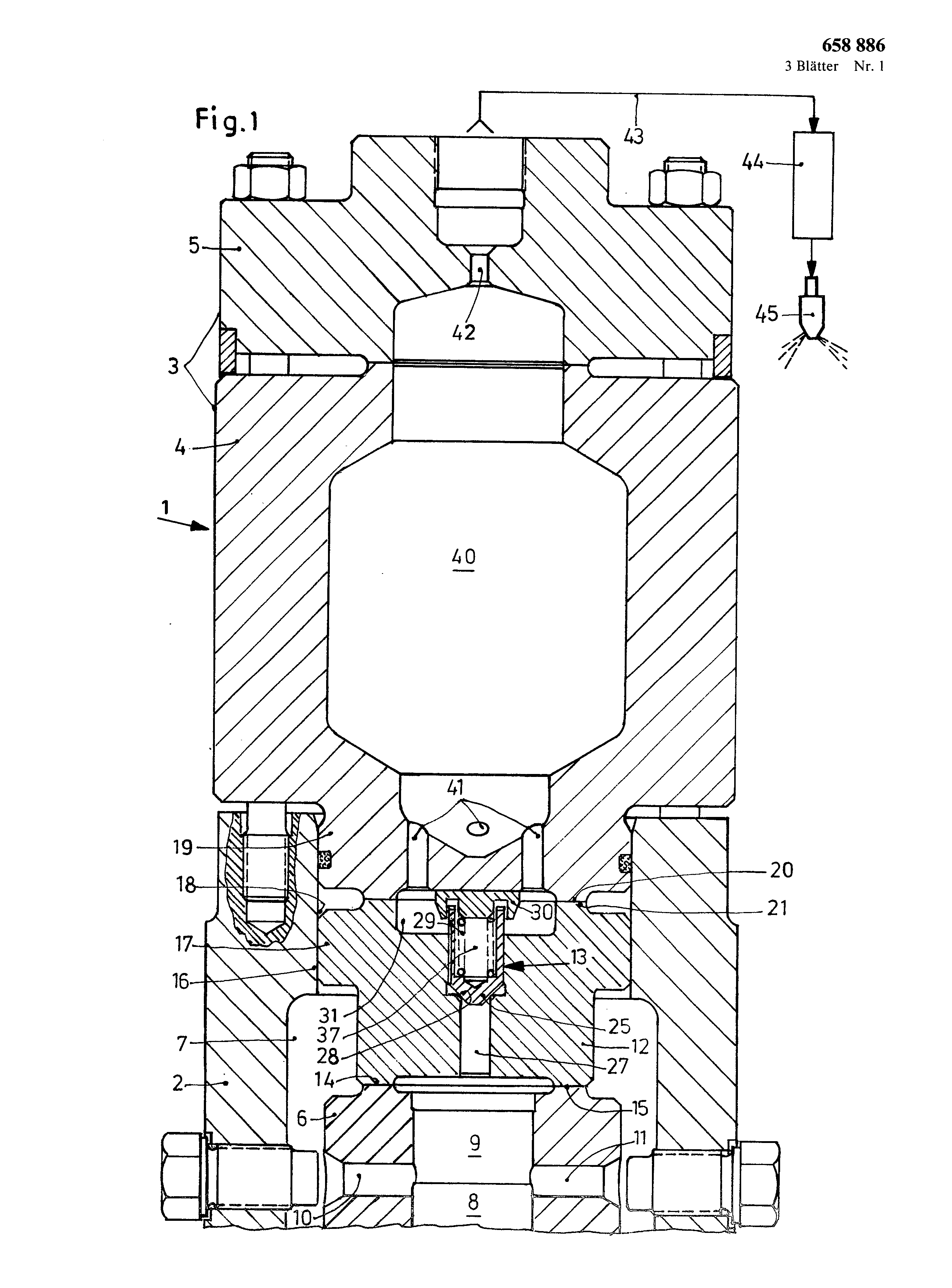
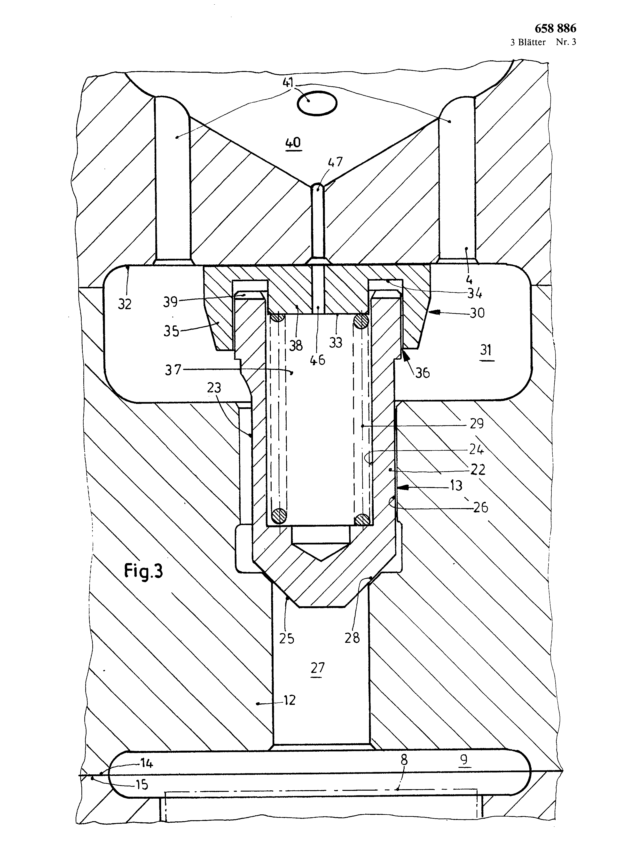
Fig. I a cut dutch for the description of the invention substantial Tell of a Brennstoffpumpe with a counter bearing in accordance with eat a first Ausffihrungsbeispiel, Fig. 2 an increased cutout from Fig. 1 within the range of the pressure control valve, Fig. 3 a variant in Fig. 2 arrangement shown within the range of the pressure control valve and its Widerlager.
In the figures gleietie or appropriate BauleJ is] e of the Uberslchtlicbkeit ha] prays each other with gleicben BezugszeJthen versehen.
In the design (Fig. 1) is marked with 1 a Brennstoffpumpe, with 2 their lower Pumpengehguseteil and with 3 their upper Pumpengehtiuseteil, what latter again of a lower Tell 4 as well as an upper Tell consists. With 6 in the Pumpengehttuseteil 2 assigned a pump cylinder, with 7 these surrounding Saugeine, is diameter-smaller Zuffihrbohrung branching from the pumping jerk area 9 27 than kegeliger valve seat 28 trained is angedrfickt, against the pressure control valve 13 by a compression spring 29 working in Sehliessrichtung ist.
The latter is in the blind hole drilling 24 of the pressure control valve 13 gef hrt and einenends at their ground as well as andernends one at a counter bearing 30 abgestfitzt, which is surrounded by a fuel collecting area 31. The latter is dutch corresponding with one another a figurations at the top side of the Ventiltragers 12 as well as at the lower surface pump-goes iuseteiles 4 begrenzt.
The counter bearing 30 is erfindungsgemtiss to the Bodenfl iche 32 at the Ventiltr more ger ansehliessenden themselves pump-goes seteiles 4, radially mobile against Jber to this abgest tzt.
Furthermore the counter bearing 30 is trained in accordance with ss the invention as Dtimpfungsk6rper, which exhibits an internal Bodenflfichemeil 33 to the Abstfitzung of the compression spring 29 and a tiusseren Bodenfl ichenteil 34 for the stroke way limitation of the pressure control valve 13 as well as kappenfOrmig with a iiusseren ringf6rmigen federation surrounds rfickw the rtige end of the pressure control valve 13; the latter erfindungsgemtiss in such a manner that a small gap is given to 36 defined width, fibre the fuel throttled into by the Saeklochbohrung 24 of the Druekventils 13 as well as the Bodenfl che 33 of the counter bearing rttumlich limited a Dtimpfungsdruckraumes 37 feedable as well as from this with each Offnungshub of the Druekventils I3 likewise throttled and purposeful DSmpfung the same more wJeder out leadable ist.
The internal Bodenfltichenteil 33, at which the compression spring 29 abstfitzt itself, is arranged at an axial projection/lead 38 of the counter bearing 30, which projection/lead possesses and into these immerses a smaller diameter than the bag RST 24 in the pressure control valve 13. At the counter bearing-lateral end of the Druekventiles 13 transverse slots 39 are arranged, the one area, with 8 in the pump cylinder 6 working pump pistons, with 9 a Pumpendruekraum, with 10 and 11 one latter each with the suction area 7 connecting suction port and with I2 a Ventiltrgger fiir eln Druekventil I3 designation. The pump piston 8 stands for the cam of a cam shaft in make contact in not represented way fibre a Pumpenst Sssel rnit. The pump cylinder 6 is abgestfitzt to its lower, not represented end in the lower Pumpengehtiuseteil 2; at an upper ringf6rmigen frontflat 14 is tzt the Ventiltriiger 12 with a lower plant-flat for this corresponding 15 abgesti. The Ventiltrager 12 is ssig coaxially centered regarding the pump cylinder 6 fibre outside by means of the Aussenfl che 16 of a federation 17 arranged at it in an interior drilling 18 of the lower pumping tightness MUSE part of 2 lagem. In addition by the interior drilling 18 the upper Gehguseteil 3 is centered by means of at its lower part 4 vorspcingend arlgeordneten Fiih of ngsbundes 19 lagemiisslg coaxially regarding the Ventiltr more iger 12, to its upper ringf6rmiger Stirnfl before 20 again the Gehiiuseteil 3 with a corresponding Ringfltiche 21 abgesttitzt ist.
The three pump-go iuseteile 2, 4 and 5 are connected by means of Sehrauben, whereby dureh this screw connection of the GeMuseteile at the same time also the pump cylinder 6 and the Ventiltr more ger 12 in the Pumpengehtiuse firmly clamped sind.
In its details and its arrangement well from Fig.
2 evident pressure control valve 13 are switched into the pump-internal fuel way and possess a cylindrical Ffihrungsscbaft 22 with at least a tiusseren Brennstoffdurehlass 23 on in form of a Abfr isung and long groove, in addition a to the rear open blind hole drilling 24 as well as in front a closing cone 25. The pressure control valve 13 is geffihrt in a drilling 26 of the Ventiltr igers 12, their upper course into unhindered Zuund Ausstr6men of the fuel into that and/or from the D mpfungsdruekraum 37 gewtihrleisten.
That pump-go useteil to 3 exhibits erfindungsgemtiss a Hochdruekpufferspeicherraum 40, which forms an integrated component of the Brennstoffpumpe 1 and at the input side with the fuel collecting area 31 more tiber several yon for this outside of the counter bearing 30 branching Durchlasskangle 41 as well as at the output more tiber a diameter-smaller Drosselbohrung 42 with a fuel line 43 is connected, again - as represented in the design only schematically - to a high pressure memory the 44 of a Brennkraftmasehine to the supply yon at this attached Einspritzventilen 45 ffihrt. The high pressure buffer memory area serves thereby in favourable way for the fact that pressure peaks in the fuel, which arise with the F6rderhub of the pump piston 8 are so far reduced that sic no schttdlichen effects in the Brennsroffleitung 43 more cause kOnhen.
Alternatively to into the Fig. 1 and 2 shown Ausgestaltungsm6glichkeit of the counter bearing 30 can do the latter in accordance with ss a further, in Fig. 3 represented Ausffihrungsvariante zus itzlich a central, continuous Drosselbohrung 46 exhibits, some throttled, more tiber the gap 36 taking place fuel reloading and/or - unloading of the Dtimpfungsdruckraumes 37 to unterstfitzen is able, in addition diameter-laterally this purpose and with the high pressure buffer memory area 40 fibre is accordingly with the Gr6sse of the spar 36 co-ordinated an accordingly arranged channel 47 kommuniziert.
Below the function of the Druekventils 13 in connection with the counter bearing 30 is more ntiher descriptive. As starting point it is accepted that the pressure control valve 13 is in Sehliessstellung and the Dtimpfungsdruckraum 37 with BrennstoffaufgeffiIlt is. With the F6rderhub of the Pumpen658 886 of piston 8 6ffnet after reaching a certain pressure level in the pumping jerk area 9 the pressure control valve 13, whereby with its (3ffnungsbewegung the fuel from this, in the Dimpfungsdruckraum 37, more tiber the gap 36 throttled into the fuel collecting area 3 I, with in Fig. 3 variant shown is pressed out zus itzlich fibre the Drosselbohrung 46 and the channel 47 into the high pressure buffer memory 40, so that a purposeful D is ihfleistet mpfung the pressure control valve 13 with its Offnungshubbewegung and soft fastening the same at the counter bearing-lateral Bodenfl ichenteil 34 gew. Then fibre fuel-arrives the Zufiihrbohrung 27, which fuel collecting area 31 as well as the Durchlasskan ile 41 into the high pressure buffer memory area 40, in which Oberh6hte pressure peaks are reduced, and from this more tiber the Drosselbohrung 42 as well as the fuel line 43 at the Hochdruekspeicher the 44. in the pressure control valve-laterally now approved fuel way of the pumping jerk area 9
After completion of the FSrderhubes and protecting the Saughubes of the pump piston 8 following to it the pressure control valve 13 becomes by the Druckausiibung of the compression spring effective in closing direction 29 again into its closing situation zuriickgef0hrt. The thrust force of the compression spring 29 is only so largely gew ihlt due to the D inoculation of the fuel effective in Offnungsrichtung in the D inoculation pressure chamber 37 that a RtickfOhren of the pressure control valve 13 into the closing situation with the decrease of pressure in the pumping jerk area 9 is gewihrleistet. This guarantees that the pressure control valve 13 also with its closing cone 25 relatively softly at the valve seat 28 gt anschl. The eigentliehe thrust force only after latches of the pressure control valve 13 by from the outside the fuel verz6gert, penetrating working in closing direction, with high pressure, however throttled by the gap 36 and/or the Drosselbohrung 46 into the steaming pressure chamber 37 wirksam.
It is from there with simple means a long service life of the pressure control valve also with extremely high Brennstoffd cken gew hrieistet and in addition the danger of a Zubruchgehens of the pressure control valve practically switched off. Furthermore on the one hand an effective dismantling is yon pressure peaks in the gef6rderten fuel secured by unity attitude of a high pressure buffer memory area with throttled exit; on the other hand a fuel line can warden used, only with the pressure level given in the high pressure memory co-ordinated its muss.
3 sheet designs 3 Blfitter No. 1 I 31 3 9 8 Fuel is supplied to the high- pressure reservoir (44) of an internal- combustion engine, to supply the injection valves (45), via a fuel path leading from the piston pump pressure chamber (9), which path includes a pressure valve (13) opened by fuel pressure and closed by a compression spring (29). The pump housing portion (3, 4, 5) to which the valve carrier (12) of the pressure valve (13) is connected, has a high-pressure buffer storage chamber (40) for reducing the harmful excess pressure peaks which occur in the fuel supplied during the working stroke of the piston pump, which chamber is connected on its inlet side via ducts (41) to a fuel collecting chamber (31) surrounding the pressure valve (13) and on its outlet side via a choke bore (42) to a fuel line (43) leading to the high- pressure reservoir (44). The pressure valve (13) has a hollow interior (37), and an abutment (30) cooperates with the pressure valve (13) to throttle the flow of fuel into and out of the chamber (37) to damp the valve movement. <IMAGE> 1. A fuel pump for supplying fuel to the high-pressure reservoir of an internal combustion engine, from which the injection valves may be supplied, including a piston pump the pressure chamber of which is connected to a pressure valve element which is arranged to open in response to pressure in the pump pressure chamber and to close, under spring force, against a valve seat, there being provided in the pump housing and connected in the fuel path down-stream of the pressure valve a high-pressure buffer storage chamber the outlet of which is constituted by a choke bore connectible to a fuel line leading to the high-pressure reservoir. 2. A fuel pump as claimed in claim 1, in which the pressure valve is located in a valve carrier located in the pump housing, there being a fuel collecting chamber into which fuel can flaw when the pressure valve opens, the high-pressure buffer storage chamber being connected on its inlet side to the fuel collecting chamber. 3. A fuel pump as claimed in claim 2, in which the high-pressure chamber is connected to the fuel collecting chamber by more than one passage. 4. A fuel pump as claimed in any one of claims 1 to 3, in which the pump housing portion containing the high-pressure buffer storage chamber is centred with an axially projecting spigot in the pump housing portion receiving the valve carrier. 5. A fuel pump as claimed in claim 4, which has a piston pump the pump cylinder of which is also co-axially aligned with the pressure valve in the valve carrier, and in which the respective pump housing portions are secured by common fixing elements. 6. A fuel pump as claimed in any one of the preceding claims, in which the valve element is generally cylindrical and has a hollow interior, and an abutment member is provided which limits the opening movement of the valve element. 7. A fuel pump as claimed in claim 6, in which a closing compression spring is located in the hollow interior of the valve element, which acts against the abutment member. 8. A fuel pump as claimed in claim 6 or claim 7, in which the abutment member is cap-shaped with an annular collar surrounding the valve element. 9. A fuel pump as claimed in claim 8, in which an inner bottom surface portion of the abutment member, on which the compression spring is supported, is disposed on an axial projection of the abutment member, which projection has a smaller diameter than a blind bore in the valve element and dips into this, and an outer bottom surface portion of the abutment member serves to limit the opening of the valve element. 10. A fuel pump as claimed in claim 8 or 9, in which in the end of the valve element which contacts the abutment member, grooves are arranged to permit fuel to flow into or out of the hollow interior of the valve element. 11. A fuel pump as claimed in any one of claims 8 to 10, in which a choke bore is provided in the abutment member, which communicates with the high-pressure storage chamber and which sustains a throttled fuel charging and discharging of the hollow interior of the valve element. 12. A fuel pump as claimed in any one of claims 6 to 11, in which the abutment member is supported in such a way that it is radially movable with respect to the valve element. 13. A fuel pump as claimed in any one of claims 6 to 12 as appendant to claim 2, in which the fuel collecting chamber surrounds the abutment member. 14. A fuel pump as claimed in any one of the preceding claims, in which the valve element has a conical valve closure portion adapted to close against a conical seat. ■ 15. A fuel pump as claimed in any one of the preceding claims, in which the valve element is slidably arranged in a bore in the or a valve carrier and forms with the bore one or more fuel passages through which fuel flows when the valve element moves to an open position. 16. A fuel pump as claimed in any one of the 1preceding claims, in which the movement of the valve element is damped. 17. A fuel pump as claimed in claim 16, in which the valve element movement is damped by virtue of throttled flow of fuel into or out of its 1hollow interior during movement of the valve element. 18. An internal combustion engine having Printed for Her Majesty's Stetionery Office by the CourierLeamington Spa, 1982. Published by the Patent Office, 25 Southampton Buildings, London,from which copies mey be obtained