Exhaust pump system.
TECHNICAL AREA the available invention concerns an exhaust pump system in accordance with generic term of the patent claim 1.
STATE OF THE ART to sucking off body fluids from body cavities or wounds is usually used within the medical range stationary suction systems. These suction systems consist essentially of a suction source, in particular a vaccum pump, a Fluidoder secretion collector, a surge tank as well as feeder lines, in particular a Drainageoder secretion line, arranged between them, a feeder line leading from the collector to the surge tank and a Vakuumleitung. connecting leading from the patient to the fluid collector the surge tank with the suction source
It was meanwhile recognized that it is important for the welfare process that the patient moves as fast as possible and leaves the bed. There is therefore meanwhile portable suction systems well-known, which are used by the majority in the Wunddrainage. WHERE 2007/128 156 reveal a such portable exhaust pump unit. It exhibits a housing with a pumping aggregate arranged therein as well as a fluid collector. This container is solvable connected with the housing, by being swingable held in appropriate guidance of two managing side panels of the housing. A drainage hose Iässt into the housing put themselves with its patient-lateral end designed as adapters and with the fluid collector in such a way verbinden.
Such devices worked in practice. The professional world works purposefully on it, as small a one as possible to create compact and quiet pump for a multiplicity from applications to which besides simply operably its soll.
No practicable solution is offered however for patients, with who in different places body fluids are to be sucked off. If only one pump with a branched hose is used, then the increased danger exists that the hose within the range of the piece of Y connector is clogged. If several devices are used, then this increases the costs of the treatment and the maintenance personnel must serve a multiplicity of devices and überwachen.
REPRESENTATION of the INVENTION it is therefore a task of the invention to create an exhaust pump system which for simultaneous sucking off of body fluids of a patient in different places suitably ist.
This task solves an exhaust pump system with the characteristics of the patent claim 1.
The exhaust pump system according to invention for sucking off body fluids of a patient exhibits a housing, at least one pumping aggregate and at least one fluid collector, which are connected with the pumping aggregate by a Vakuumleitung. That at least a pumping aggregate is arranged in the housing and the housing points more than one admission to the solvable and simultaneous mounting plate of the fluid collector auf.
Since more than one fluid collector with the housing is connectable, more than one hose can be used. These hoses know thus to different places of the patient led and in different body cavities or at different places the same body cavity of fluids absaugen.
The fluid collectors can be fastened in well-known way in or at the housing. They can in particular swingable, insertable or over indirect liaison vehicles at the housing positionable and fastenable sein.
By fluids among other things all sorts are understood about body fluids, secretions and fat, like them for example during operations, in the Wunddrainage, the thorax drainage and during the fat exhaust result here können.
The exhaust pump system according to invention Iässt in particular for Cardio drainage and for Pleura drainage use themselves. Both kinds of drainage leave themselves at the same time with the same system according to invention durchführen.
Preferably the system is portable ausgebildet.
It is favourable that by the increase of the number of fluid collectors the capacity for the body fluid quantity which can be collected is increased. Since for each place and/or each body cavity which can be sucked off its own fluid collector can be made available, Iässt the kind and the quantity of the sucked off fluid also better to supervise itself. It is not mixed with fluids from other suction places. It is however still possible to seize several suction places in groups together and their sucked off fluids into the same fluid collector too leiten.
Advantages way is however connected to each fluid collector by its own drainage hose with the patient. Each drainage hose is connected thereby preferably with its own fluid collector, so that in the mathematical sense a biunique connection between fluid collectors and body cavity production ist.
This facilitates for the medical technical personnel the analysis and monitoring, since for each fluid collecting point on the basis the associated fluid collector can be determined, which kind liquid and in which quantities this liquid anfällt.
Owing to the exhaust pump system according to invention thus no more bypasses of the hoses are and thus no pieces of Y connector of hoses notwendig.
The risk that the hoses clog, as this happens in particular on the pieces of Y connector frequently are thereby minimiert.
In a preferential execution form the photographs to the admission of the fluid collectors, arranged at the equipment, are identically trained. The system can use identically and equally large trained fluid collectors. In addition, it can take up different fluid collectors. The differences know for example in the form, in the size, in the kind of the filters, in the kind of the fluid becoming lumpy means or in the kind in or at the container arranged sensors bestehen.
The system can be provided with differently trained photographs however also, to which only in each case according to formed fluid collectors are taken up können.
Preferably are the photographs next to each other angeordnet.
In a simple execution form only one pumping aggregate with only one vaccum pump is arranged in the housing. This pump is over in the housing running internal or outside of the housing running external Vakuumleitungen connected with the fluid collectors. This simple execution form exhibits the advantage that it economically, relatively easily and relatively small ist.
In other execution forms at least two pumping aggregates and/or vaccum pumps are arranged in the housing. Each of these vaccum pumps is connected by internal or external Vakuumleitungen with at least one fluid collector. A biunique connection is preferential also here, so that its own pump is assigned to each fluid collector. This system exhibits the advantage that in case of failure on another in the same housing are changed for a pump kann.
It is also possible that a pump several fluid collectors with negative pressure beaufschlägt.
In the housing at least control electronics, also PCB (printed Circuit board) is mentioned and arranged. This control electronics serves for the operation of the pumping aggregate, whereby it processes and uses received signals from possible sensors. In a simple execution form this control electronics is assigned to several and/or all pumping aggregates and operates thus several and/or all vaccum pumps. This reduces the costs. In other execution forms each pumping aggregate, i.e. each vaccum pump are assigned, to its own control electronics. Thus again a biunique allocation is present. Also several groups can be formed by pumping aggregates, which are to be control electronics-assigned to a their own. The different controls can be applied on the same printed circuit board. Preferably however each control exhibits its own printed circuit board. If several controls are used, then these can on the appropriate application, like e.g. Cardio drainage or Pleura drainage, to be optimized. The moreover one the other pump still is funktionsfähig. in case of a loss of a pump and/or control electronics
The system exhibits at least Eingabeund display unit. If several units are present, then are they preferably in each case only one fluid collector and/or in each case only one pumping aggregate zugeordnet.
They know however also groups assigned of it sein.
Advantages way is in the housing at least one battery present for the current supply of electronics and the pump engine. It can be present only one battery for all pumps or each pump can its own battery be assigned. The moreover one also a group can be connected with a battery by pumps and another group of another battery. The connection with the public line is preferably likewise möglich.
Preferably modules specified of individual elements of the above are present, which are combined into a common system in a common housing. These modules cover for example one pumping aggregate each, one fluid collector each, one control electronics each and one Eingabeund each display unit and optionally still one battery each. Preferably at least Eingabeund display unit as well as the associated fluid collector is in such a way arranged that a user display units form a biunique allocation Eingabeund to the appropriate fluid collector kann.
Preferably all modules exhibit the same width, so that a same division of the housing available ist.
Thus the individual modules can be exchanged simply. It Iässt for example with the same construction units a system arrange themselves, which two Cardio applications and an Pleura application exhibits, and another system, which one Cardio application and two Pleura applications aufweist.
A large advantage of the system according to invention is that only one equipment gives a multiplicity of possibilities to the user and nevertheless a simple operation permitted. The physician and/or the maintenance personnel can decide, which and how many are used the provided drainage container. He can select also the size of the drainage containers. The physician and/or the maintenance personnel can decide, how many pumps and which kind pumps and/or control is to be used. It knows Pleuraund Cardio drainage and further kinds of drainage with the same equipment at the same time durchführen.
Further execution forms are in the dependent requirements angegeben.
SHORT DESCRIPTION of the DESIGNS preferential execution forms of the invention in the following on the basis the designs are described, which serve only for the explanation and not restrictivy to be laid out are. In the designs show:
Fig. 1 Fig. 2 Fig. 3 Fig. 4 Fig.
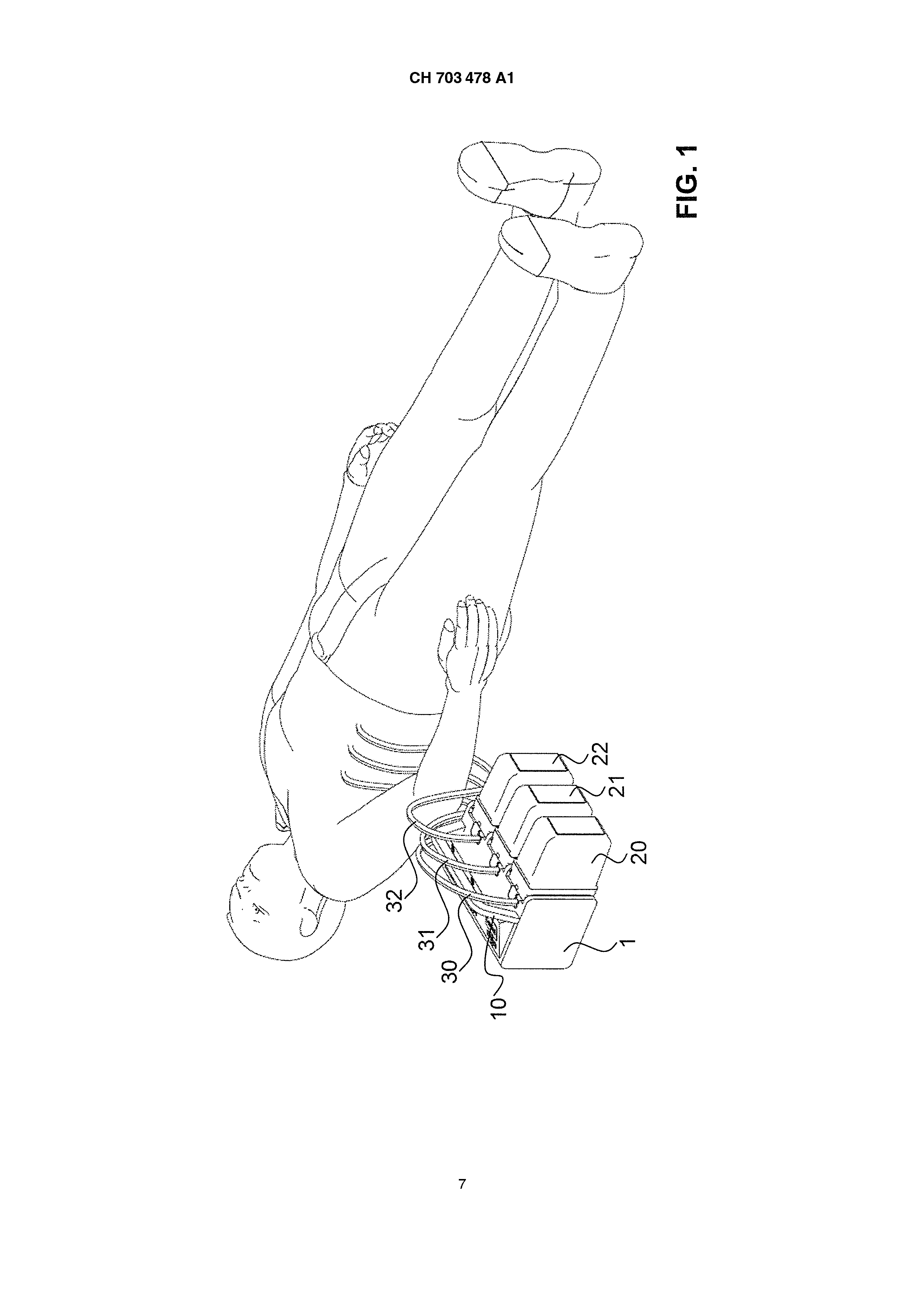
Fig. 6 a schematic representation of an exhaust pump system according to invention in the employment with a patient in a first execution form; a schematic perspective representation of an exhaust pump system according to invention in a second execution form from a first side; the exhaust pump system in accordance with Fig. 2 from a second side; a schematic representation of the exhaust pump system in accordance with Fig. 2; a schematic representation of the exhaust pump system according to invention in a third execution form and a schematic representation of the exhaust pump system according to invention in a fourth Ausführungsform.
DESCRIPTION of PREFERENTIAL EXECUTION FORMS in Fig. 1 is represented a first example of a Absaugpumpeneystems according to invention. It is designed as portable equipment. It exhibits a housing 1 with a Traggriff 10 trained as carrying the equipment. In the housing 1 at least one pump unit, i.e. a vaccum pump are, arranged. At the housing fluid collectors 20, 21, 22 are fastenable. Here they are by means of in Fig. 3 visible engaging handles 120, 121, 122 in their position gehalten.
Preferably the housing 1 exhibits an admission, into which the collectors are 20, 21.22 in their desired customs position insertable or swingable. The fluid collectors 20, 21.22 are preferably next to each other arranged, whereby all photographs equivalent trained sind.
Furthermore secretion hoses, here drainage hoses 30, are 31.32, present mentioned. These lead to a patient. More einoder mehrlumige hoses can be. Each hose exhibits a drainage line. Furthermore preferably a service line with a smaller diameter is present, which for example for the flushing of the line dient.
As in Fig. 3 is recognizable, are connected the pump-lateral ends of the drainage hoses 30, 31.32 with Kopplungsteilen 310, 311.312, which are insertable into the housing and which thereby ever a drainage connection with ever a neighbouring fluid collector 20, 21.22 erstellt.
In the use by means of the vaccum pump and a Vakuumleitung in the respective fluid collector 20, 21.22, running in the housing 1, a vacuum and/or a negative pressure is produced. By the connection of the fluid collector 20, 21, 22 with the respective drainage hose 30, 31, 32 a negative pressure in the body cavity of the patient is applied. Body fluid is sucked through the drainage hose 30, 31.32 into the fluid collector 20, 21.22 and there gesammelt.
It is also possible, the drainage hoses 30, 31.32 direct instead of in the housing 1 into the fluid collectors 20 to put 21.22 in. Besides it is possible that drainage hoses 30, 31.32 with the respective fluid collector 20, 21.22 stand in a not without destruction solvable connection. This is favourable, since both fluid collectors 20, 21.22 as well as drainage hoses 30, 31.32 are a one-way product, which must be disposed of after use professionally. The housing 1 with that at least a vaccum pump however is repeated einsetzbar.
Preferably the drainage hoses 30, 31.32, in particular the drainage lines are normal, so that a 1:1 connection between fluid collectors 20, 21.22 and the patient can be created. The hoses can to different places of the patient body supplied werden.
In the example in accordance with Fig. 1 all fluid collectors 20, 21.22 are equivalent trained and wise in particular the same size and the same capacity up. In the example in accordance with the Fig. 2 and 3 one is smaller and with smaller capacity trained the fluid collector 22 than the two other fluid collector 20, 21.
Also different relative importance can be selected and/or each fluid collector Iässt with another capacity and/or form be formed. Preferably the photographs of the housing 1 are in such a way trained that differently large fluid collectors take up the same admission kann.
Into the Fig. 2 and 3 a console 11 is identifiable by the housing 1, on which at least Eingabeund is present display unit. The console 11 is bent trained in this example. The announcement preferably exhibits a display area (a display) 110, 111, 112. As input fields 113, 114, 115 leaves themselves represented like here to input keys, rotary buttons or other suitable means verwenden.
Into the Fig. 1 to 3 represented remark examples are as modules designed. The display area 112, the input field 115 as well as the fluid collector 22 can be assigned each other clearly. This is valid also for the remaining display areas, input fields and fluid collectors. At least the individual outside elements of the modules, i.e. the elements the inclusive associated photographs of the housing 1 specified above, are preferably next to each other arranged. This facilitates the overview and the Zuordnung.
Leave themselves thus, like this in the Fig. 2 and 3 is recognizable, with the same equipment at the same time different drainage applications would drive out. Display 112 shows a Pleura drainage, the displays 110, 111 shows two different Cardio-Drainagen.
In Fig. the inside of the housing 1 is schematically represented 4. In this remark example three pumping aggregates or vaccum pumps 40, 41.42 are present, which with one only this pump assigned control electronics 60, 61.62 are operated in each case. Also the allocation Eingabeund display units 113, 114, 115 and here the not visible fluid collector 20, 21.22 are eindeutig.
Furthermore batteries 50, 51.52 and/or power pack are present for the connection to an external line, which in this example likewise biuniquely a respective module assigned sind.
In Fig. 5 only one vaccum pump 40, only one battery 50 and/or only one power pack and only Anzeigeund input unit 113 for all fluid collectors is present. There is however still three control electronics units 60, 61, 62 available. Thus leave themselves, as in the Fig. 2 and 3 represented, at the same time different drainage applications would still drive through, whereby these are shown the same display and produced by the same vaccum pump werden.
In the remark example in accordance with Fig. 6 is also only one control electronics, preferably only one PCB vorhanden.
Further kinds of combination of the individual elements of the system are possible. In the descriptive execution forms exactly three fluid collectors in the same housing were held. Other numbers are possible, it can in particular two, four or more containers be. The number of individual elements can to be selected arbitrary and not have with the number of elements of another type to agree. So for example two pumps in combination with three containers can used werden.
The exhaust pump system according to invention makes a simultaneous sucking possible off of body fluids of a patient in different places. It is simply operable, offers to the user a large flexibility in the choice of the drainage and makes a good overview possible of the selected Applikationen.
Reference symbol list 1 housing Traggriff 11 console first display area second display area third display area first input field second input field third input field first engaging handle second engaging handle 20.21.22 30, 31.32 40, 41.42 50, 51.52 60, 61.62 third engaging handle fluid collector drainage hose first Kopplungsteil second Kopplungsteil third Kopplungsteil pumping aggregate battery control electronics A suction pump system for aspirating body fluids from a patient is disclosed. The suction pump system includes a housing, at least one pump unit, and a one fluid collection container, which is connected to the pump unit via a vacuum line. The at least one pump unit is arranged in the housing, and the housing has more than one fixture for releasably and simultaneously holding the fluid collection container. The suction pump system allows a patient's body fluids to be aspirated from different sites simultaneously. The suction pump system is easy to operate, affords the user great flexibility in terms of the choice of drainage, and permits a good overview of the chosen applications. 1. Exhaust pump system for sucking off body fluids of a patient, whereby the exhaust pump system a housing (1), at least one pumping aggregate (40, 41.42) and at least one fluid collector (20, 21.22) exhibits, whereby that at least a pumping aggregate (40, 41.42) in the housing (1) is arranged and whereby the housing (1) an admission to the solvable mounting plate of the fluid collector (20, 21.22) exhibits, by the fact characterized that the housing (1) at least two such photographs to the simultaneous mounting plate of one fluid collector each (20, 21.22) exhibits. 2. Exhaust pump system according to requirement 1, whereby furthermore drainage lines (30, 31.32) are present for the connection of the fluid collectors (20, 21.22) with the patient, whereby each drainage line (30, 31.32) is connected with its own fluid collector (20, 21.22). 3. Exhaust pump system after one of the requirements 1 or 2, whereby the photographs are identically trained. 4. Exhaust pump system after one of the requirements 1 to 3, whereby the photographs are arranged next to each other. 5. Exhaust pump system after one of the requirements 1 to 4, whereby at least two pumping aggregates (40, 41.42) in the housing (1) is arranged. 6. Exhaust pump system according to requirement 5, whereby its own pumping aggregate (40, 41.42) is assigned to each fluid collector (20, 21.22). 7. Exhaust pump system after one of the requirements 1 to 4, whereby several fluid collectors (20, 21.22) are assigned to the same pumping aggregate (40, 41.42). 8. Exhaust pump system according to requirement 7, whereby all fluid collectors (20, 21.22) are assigned to the same pumping aggregate (40). 9. Exhaust pump system after one of the requirements 1 to 8, whereby in the housing (1) at least control electronics (60, 61.62) is arranged. 10. Exhaust pump system according to requirement 9, whereby several pumping aggregates (40, 41, 42) are present and are assigned these the same control electronics (60, 61.62). 11. Exhaust pump system according to requirement 10, whereby all pumping aggregates (40, 41, 42) are assigned to the same control electronics (60, 61.62). 12. Exhaust pump system according to requirement 9, whereby each pumping aggregate (40, 41.42) is assigned to its own control electronics (60, 61.62). 13. Exhaust pump system after one of the requirements 1 to 12, whereby several Eingabeund display units (110, 115) available are and these in each case a fluid collector (20, 21.22) and/or in each case is assigned to a pumping aggregate (40, 41.42). 14. Exhaust pump system after one of the requirements 1 to 13, whereby pumping aggregate (40, 41.42), fluid collectors (20, 21.22), control electronics (60, 61.62) and Eingabeund a module form display unit (110-115), whereby at least two such modules are present. 15. Exhaust pump system after one of the requirements 1 to 14, whereby the system is portable trained.