MICROFLUIDICS-BASED NANOPARTICLE SYNTHESIS SYSTEM, AND DEVICE AND METHOD USING THE SAME
This application claims the priority benefit of Chinese Patent Application Number The present disclosure belongs to the technical field of microfluidics and nanomaterial synthesis, and in particular relates to a microfluidics-based nanoparticle synthesis system, and a device and synthesis method using the same. Nanoparticle synthesis technology is the technological frontier in the fast-growing nanotechnology field, and the unique size-dependent properties of nanoparticles allow these materials to show great advantages and play an irreplaceable role in many fields. Nanoparticle synthesis technology has been widely used in many industries, such as drug delivery, energy, electronics, and the like. Nanoparticle synthesis technology is one of the key steps to realize nanoparticle applications. Since the size properties of nanoparticles need to be used in most applications, the reproducibility of size distribution, yield and size between batches of nanoparticle synthesis are very important parameters in the evaluation of nanoparticle synthesis. One of the traditional nanoparticle synthesis methods is based on the principle of batch mixing. Particularly, raw materials for preparing nanoparticles are dissolved in an organic or aqueous phase, and then the resulting mixture is added to another aqueous or organic phase having poor compatibility with it for quick mixing in a beaker or another device by stirring. However, when the traditional batch synthesis method (mixing in a bulk solution) is used for large-scale production of nanoparticles, the synthesized particles have low quality, and there are also some uncontrollable factors, such as aggregation and heterogeneous mixing, resulting in poor size uniformity and reproducibility of nanoparticles. A microfluidics-based micro-reactor can realize rapid mixing of reagents, temperature control, and precise space-time manipulation in a reaction. When microfluidics is used for nanoparticle synthesis, mixing is controllable and uniform, thus nanoparticles with uniform size may be produced, and the repeatability of physical and chemical properties of the nanoparticles can also be precisely controlled. In addition, the microenvironment of nanoparticle synthesis may be regulated to further improve the size uniformity and reproducibility of nanoparticles, thereby improving the yield of a preparation process of the nanoparticles. At present, instruments for microfluidics-based nanoparticle synthesis in the market mainly come from Precision Nanosystems in Canada. In this instrument, a syringe pump is mainly used to push an organic phase solution and an aqueous phase solution into a microfluidic chip for mixing, and the synthesized nanoparticles are collected at the outlet of the microfluidic chip. This instrument achieves very high size controllability, uniformity, and reproducibility for nanoparticles. Since a syringe pump is used as the power source to push the fluids, there are some insurmountable disadvantages. When a flow is adjusted by the syringe pump, there are problems such as large volume, low response speed, low adjustment accuracy, existence of flow pulse, low sample usage efficiency, and being easily contaminated. The flow pulse and low adjustment accuracy will compromise the thorough mixing during nanoparticle synthesis, thereby reducing the uniformity of nanoparticles. In addition, to use the syringe pump, a reagent needs to be loaded into a syringe, which is complicated to operate and easily causes contaminations. In addition, the capacity of the syringe is limited, thus it requires much more engineering design and improvement for a scale-up production process, and it is not convenient for direct use of syringes in high-throughput production. In order to solve the deficiencies in the prior art, the present disclosure provides a microfluidics-based nanoparticle synthesis system, and a device and synthesis method using the same. The objective of the present disclosure is achieved by the following technical solutions. A microfluidics-based nanoparticle synthesis system, comprising: a microfluidic chip; a reagent bottle which is connected to the microfluidic chip; and a flow control assembly comprising a pressure controller which is used for controlling the pressure in the reagent bottle. Preferably, the microfluidics-based nanoparticle synthesis system further comprises: a washing solution bottle; a control valve by which the microfluidic chip is connected to the reagent bottle and washing solution bottle, wherein the flow control assembly is provided between the control valve and the reagent bottle and washing solution bottle. Preferably, the reagent bottle comprises an organic phase reagent bottle and an aqueous phase reagent bottle, and the washing solution bottle comprises an organic phase washing solution bottle and an aqueous phase washing solution bottle. Preferably, two flow control assemblies are provided in the system, each of the two flow control assemblies further comprises a flow sensor which is electrically connected to the pressure controller. Preferably, the system further comprises a waste liquid bottle and a collection tube, wherein the waste liquid bottle and the collection tube are each connected to the microfluidic chip through the control valve. Preferably, the control valve is a three-way valve. Preferably, the aqueous phase reagent bottle and the aqueous phase washing solution bottle are respectively connected to the normally-closed valve port and the normally-open valve port of a first three-way valve, and the common valve port of the first three-way valve is connected to the common valve port of a third three-way valve through a first flow sensor; and wherein the normally-closed valve port of the third three-way valve is in fluid communication with the aqueous phase port of the microfluidic chip, and the normally-open valve port of the third three-way valve is connected to the waste liquid bottle;
Preferably, the reagent bottle comprises an organic phase reagent bottle and an aqueous phase reagent bottle, and
Preferably, the microfluidics-based nanoparticle synthesis system further comprises: a first flow sensor, which is provided between the organic phase reagent bottle and the organic phase port of the microfluidic chip, wherein the pressure in the organic phase reagent bottle is controlled by the pressure controller based on the flow rate feedback from the first flow sensor so as to control the flow rate to reach a preset value; and/or a second flow sensor, which is provided between the aqueous phase reagent bottle and the aqueous phase port of the microfluidic chip, wherein the pressure in the aqueous phase reagent bottle is controlled by the pressure controller based on the flow rate feedback from the second flow sensor so as to control the flow rate to reach a preset value; and/or a third flow sensor, which is provided between the diluent bottle and the mixer component, wherein the pressure in the diluent bottle is controlled by the pressure controller based on the flow rate feedback from the third flow sensor so as to control the flow rate to reach a preset value. Preferably, the microfluidics-based nanoparticle synthesis system further comprises: a first control valve, which is provided between the organic phase reagent bottle and the organic phase port of the microfluidic chip, so as to control the fluid passage to be an open or closed state; and/or a second control valve, which is provided between the aqueous phase reagent bottle and the aqueous phase port of the microfluidic chip, so as to control the fluid passage to be an open or closed state; and/or a third control valve, which is provided between the diluent bottle and the mixer component, so as to control the fluid passage to be an open or closed state. Preferably, the microfluidics-based nanoparticle synthesis system further comprises: a waste liquid bottle; a fourth control valve, which is respectively connected to the mixer component, the waste liquid bottle and the collection bottle, so that the fluid discharging from the mixer component may enter the collection bottle or the waste liquid bottle. Preferably, the microfluidics-based nanoparticle synthesis system further comprises: a fifth control valve, which is provided between the organic phase reagent bottle and the organic phase port of the microfluidic chip, and connected to the waste liquid bottle, so that the fluid discharging from the organic phase reagent bottle may enter the organic phase port of the microfluidic chip or the waste liquid bottle; and/or a sixth control valve, which is provided between the aqueous phase reagent bottle and the aqueous phase port of the microfluidic chip, and connected to the waste liquid bottle, so that the fluid discharging from the aqueous phase reagent bottle may enter the aqueous phase port of the microfluidic chip or the waste liquid bottle. Preferably, the collection bottle is in fluid communication with the atmosphere through a filter element. Preferably, the volume of the organic phase reagent bottle, the aqueous phase reagent bottle and/or the diluent bottle is greater than or equal to 0.1L. Preferably, the mixer component is a three-way mixer which has a three-way connector with a Y or T shape. Preferably, the microfluidics-based nanoparticle synthesis system further comprises a chip cassette in which the microfluidic chip is provided; and the chip cassette comprises: a cover board of the chip cassette; a bottom board of the chip cassette, wherein the microfluidic chip is provided between the cover board of the chip cassette and the bottom board of the chip cassette; a connector, wherein a plurality of connectors are respectively connected to the organic phase port, the aqueous phase port and outlet of the microfluidic chip, so as to connect to the organic phase reagent bottle, the aqueous phase reagent bottle and the mixer component. Preferably, the connector is a Luer connector. Also provided herein is a device using the above mentioned microfluidics-based nanoparticle synthesis system, which comprises a bench, wherein a microfluidic chip assembly and a flow control assembly are provided above the bench, and the organic phase reagent bottle, the aqueous phase reagent bottle, the organic phase washing solution bottle, and the aqueous phase washing solution bottle are provided side by side below the bench; and the waste liquid bottle is provided at an inner side of the reagent bottle. Preferably, a height-adjustable sampling needle assembly is provided on each of the organic phase reagent bottle and the aqueous phase reagent bottle. Preferably, the microfluidic chip assembly comprises a base and a transfer tooling embedded in the base, and a chip is provided in the transfer tooling; a flip cover is provided at one side of the base, and a locking mechanism for locking the flip cover is provided at the other side of the base; the inner wall of the flip cover is provided with a guide rod for cooperating with a protruding sample injection channel on the chip, and a through hole is formed in a center of the guide rod; and Also provided herein is a synthesis method using the above mentioned microfluidics-based nanoparticle synthesis system, which comprises the following steps:
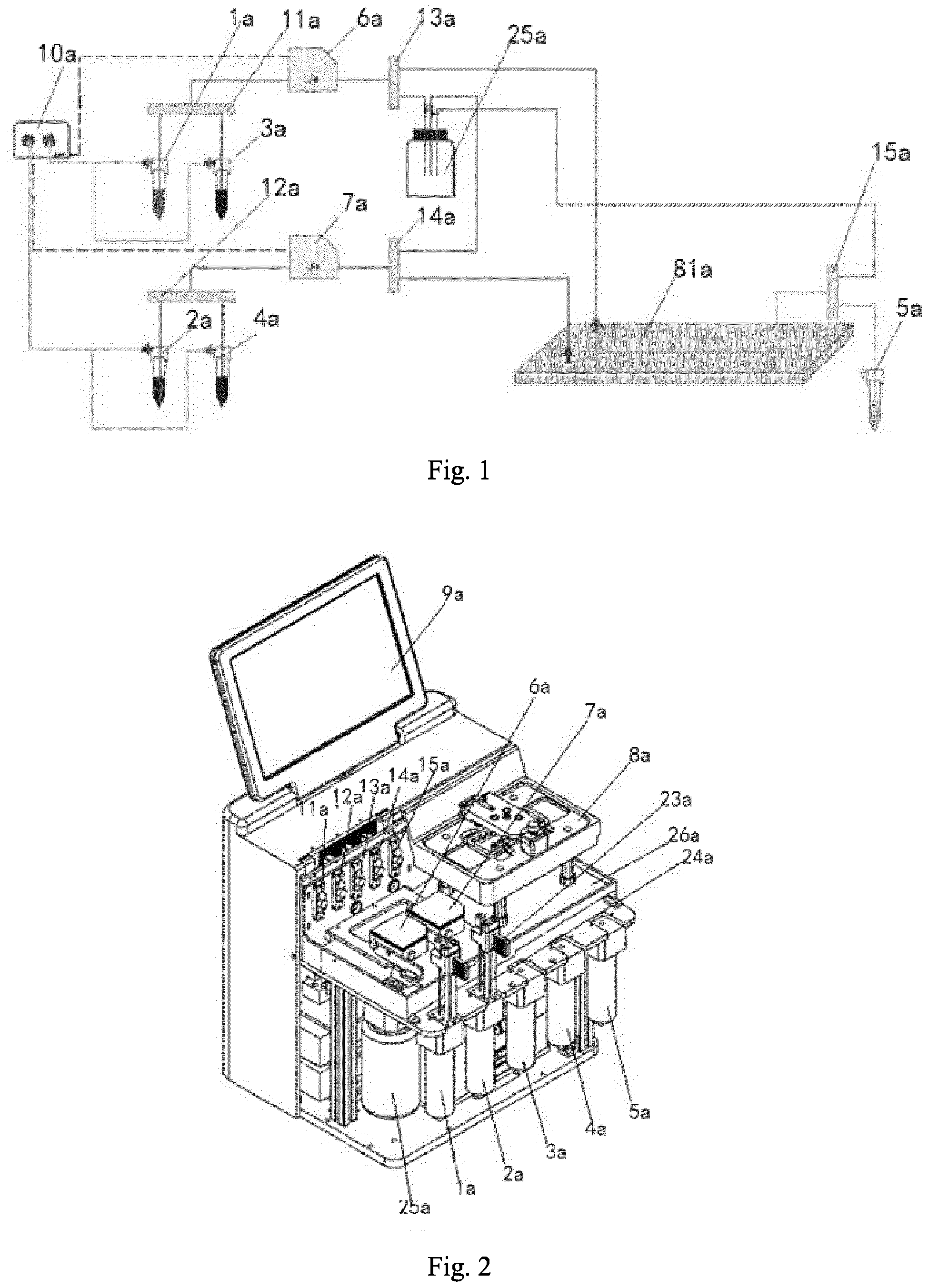
Preferably, the method further comprises pre-processing steps before synthesis steps: using the flow control assembly to extrude out the aqueous phase and the organic phase respectively from the aqueous phase reagent bottle and the organic phase reagent bottle according to the presetting, and allowing the aqueous phase and the organic phase to enter the waste liquid bottle correspondingly through the three-way valves for removing bubbles in pipelines. Beneficial effects of the present disclosure: the system achieves high-accuracy flow control, and it is used in combination with a microfluidic chip having high-efficiency and rapid mixing effect to finally achieve high-throughput and high-uniformity nanoparticle synthesis. The same instrument may be adjusted by a user as required to achieve different throughputs without redesigning the instrument. In the figures, 1a represents an aqueous phase reagent bottle; 2a represents an organic phase reagent bottle; 3a represents an aqueous phase washing solution bottle; 4a represents an organic phase washing solution bottle; 5a represents a collection tube; 6a represents a first flow sensor; 7a represents a second flow sensor; 25a represents a waste liquid bottle; 11a represents a first three-way valve; 12a represents a second three-way valve; 13a represents a third three-way valve; 14a represents a fourth three-way valve; 15a represents a fifth three-way valve; 18a represents a fan; 23a represents an aqueous phase sample injection needle assembly; 24a represents an organic phase sample injection needle assembly; 26a represents a bench; 31a represents a base; 32a represents a flip cover; 33a represents a guide rod; 34a represents a pressing block; 35a represents a spring; 36a represents a snap; 332a represents a sealing ring; 8a represents a microfluidic chip assembly; 81a represents a microfluidic chip; 82a represents a groove; 83a represents a sample injection channel; 84a represents a transfer tooling; 9a represents an operation screen; and 10a represents a pressure controller. 1b represents a microfluidic chip; 2b represents an organic phase reagent bottle; 3b represents an aqueous phase reagent bottle; 4b represents a collection bottle; 5b represents a pressure controller; 6b represents a diluent bottle; 7b represents a mixer component; 8b represents a first flow sensor; 9b represents a second flow sensor; 10b represents a third flow sensor; 11b represents a first control valve; 12b represents a second control valve; 13b represents a third control valve; 14b represents a waste liquid bottle; 15b represents a fourth control valve; 16b represents a chip cassette; 16-1b represents a cover board of the chip cassette; 16-2b represents a bottom board of the chip cassette; 16-3b represents an connector; 17b represents a IPC (industrial personal computer); 18b represents an emergency stop switch; 19b represents an input port of external gas source; 20b represents an output port of air pressure. The present application discloses a microfluidics-based nanoparticle synthesis system in the first embodiment. As shown in The reagent bottles may comprise an aqueous phase reagent bottle 1a and an organic phase reagent bottle 2a; and the washing solution bottles may comprise an aqueous phase washing solution bottle 3a and an organic phase washing solution bottle 4a. The system may further comprise a waste liquid bottle 25a and a collection tube 5a that are respectively connected to the microfluidic chip 81a through a control valve. Two flow control assemblies may be provided in the system, and each of the flow control assemblies may comprise a flow sensor and a pressure controller 10a which is electrically connected to the flow sensor. Particularly, the aqueous phase reagent bottle 1a and the aqueous phase washing solution bottle 3a may be respectively connected to the normally-closed valve port and the normally-open valve port of a first three-way valve 11a, and the common valve port of the first three-way valve 11a may be connected to the common valve port of a third three-way valve 13a through a first flow sensor 6a; the normally-closed valve port of the third three-way valve 13a may be in fluid communication with an aqueous phase port of the microfluidic chip 81a, and the normally-open valve port of the third three-way valve 13a may be connected to the waste liquid bottle 25a. The pressure controller 10 may be connected to the air pressure control end of each of the aqueous phase reagent bottle 1a and the aqueous phase washing solution bottle 3a, and the pressure controller 10a may be electrically connected to the pressure control end of the first flow sensor 6a through a data cable. The organic phase reagent bottle 2a and the organic phase washing solution bottle 4a may be respectively connected to the normally-closed valve port and the normally-open valve port of a second three-way valve 12a, and the common valve port of the second three-way valve 12a may be connected to a second flow sensor 7a; and the second flow sensor 7a may be connected to the common valve port of a fourth three-way valve 14a, and the normally-open valve port of the fourth three-way valve 14a may be in fluid communication with the waste liquid bottle 25a. The pressure controller 10a may be connected to the air pressure control end of each of the organic phase reagent bottle 2a and the organic phase washing solution bottle 4a, and the pressure controller 10a may be further connected to the pressure control end of the second flow sensor 7a through a data cable. The waste liquid bottle 25a may be further connected to the normally-open valve port of a fifth three-way valve 15a, the normally-closed valve port of the fifth three-way valve 15a may be connected to the collection tube 5a, and the common valve port of the fifth three-way valve 15a may be connected to an outlet of the microfluidic chip 81a. A first power module, a second power module, and the flow control assembly may be each electrically connected to a main control unit. The present application also discloses a device using the microfluidics-based nanoparticle synthesis system described above, which comprises a housing formed by left and right parts that match with each other. The housing is provided with an operation screen 9a, one inner side of the housing is provided with a pipeline control zone, and the other inner side is provided with an industrial control zone for controlling pipelines. The pipeline control zone may comprise a bench 26a, and a microfluidic chip assembly 8a and a flow control assembly may be provided side by side above the bench 26a. The flow control assembly may comprise a first flow sensor 6a and a second flow sensor 7a. The microfluidic chip assembly 8a may be exposed on the housing. The aqueous phase reagent bottle 1a, the organic phase reagent bottle 2a, the aqueous phase washing solution bottle 3a, the organic phase washing solution bottle 4a, and the collection tube 5a may be provided side by side below the bench 26a, and the waste liquid bottle 25a may be provided at the inner side of the reagent bottle. The reagent bottles can have different volumes as required, and generally, the reagent bottles may each adopt a threaded connection to form an airtight connection with the device. The aqueous phase reagent bottle 1a and the organic phase reagent bottle 2a may be respectively provided with a height-adjustable aqueous phase sample injection needle assembly 23a and a height-adjustable organic phase sample injection needle assembly 24a. In order to well cooperate with the sample injection needle assembly to control the height of a sample injection needle, a height adjustment groove may be correspondingly formed on the housing, and a height control part of the sample injection needle assembly may penetrate through the groove and be provided outside the housing. The microfluidic chip assembly 8a may comprise a base 31a and a transfer tooling 84a embedded in the base 31a, and a micro fluidic chip 81a may be provided in the transfer tooling 84a. A sample injection channel 83a may be provided protruding on the microfluidic chip 81a, and a sealing ring 332a may be provided in the sample injection channel 83a. In order to well identify the sample injection channel, the transfer tooling 84a and the base 31a may be each provided with a corresponding sample injection mark. In this embodiment, the sample injection mark of the transfer tooling 84a may be a groove 82a. Since the chip generally has three channels, three grooves 82a may be provided in this embodiment. Correspondingly, the sample injection mark of the base 31a may be a protrusion matching the groove 82a. A flip cover 32a may be provided at one side of the base 31a, and a locking mechanism for locking the flip cover 32a may be provided at the other side of the base 31a. A snap 36a may be provided on the locking mechanism. An inner wall of the flip cover 32a may be provided with a guide rod 33a that cooperates with a protruding sample injection channel 83a on the microfluidic chip 81a, and a through hole 331a may be formed in the center of the guide rod 33a. Particularly, the flip cover 32a may be provided at one side of the base 31a through an elastic assembly, and the pivot of flip cover 32a may be provided on the elastic assembly. The elastic assembly may comprise a pressing block 34a, and a spring 35a may be arranged between the pressing block and the base 31a. The flip cover 32a may be flipped to drive the pressing block 34a to press the spring 35a, and the flip cover 32a may be locked to the microfluidic chip 81a through the snap 36a. In a locked state, the guide rod 33a presses against the sealing ring 332a to form a seal with the sample injection channel 83a, and the through hole 331a in the guide rod 33a is in fluid communication with the sample injection channel 83a. The locking mechanism may be provided with a button, and the button may be linked with the snap 36a, such that the locking between the snap 36a and the flip cover 32a may be released by pressing the button. The industrial control zone may comprise a first and a second power modules, and a heat dissipation module for cooling. In this embodiment, the heat dissipation module may be a fan. Moreover, the present application also discloses a nanoparticle synthesis method using the microfluidics-based nanoparticle synthesis system described above, which comprises the following steps:
In order to make the reagent flow in the system stable, the synthesis method may further comprise pre-processing steps before synthesis steps: using the flow control assembly to extrude out the aqueous phase and the organic phase respectively from the aqueous phase reagent bottle 1a and the organic phase reagent bottle 2a according to the presetting, and allowing the aqueous phase and the organic phase to enter the waste liquid bottle correspondingly through the three-way valves for removing bubbles in pipelines. When a system pipeline needs to be cleaned, the corresponding washing solution valve port may be opened to clean the pipeline. The second embodiment of the application provided a microfluidics-based nanoparticle synthesis system, as shown in Through the above technical solution of this embodiment, the pressure in the organic phase reagent bottle 2b and the aqueous phase reagent bottle 3b may be controlled by the pressure controller 5b (for example, the pressure is controlled to a specific preset value), so that the organic phase and the aqueous phase are more stable while flowing into the microfluidic chip 1b, thereby substantively eliminating the pulsation of the organic phase and the aqueous phase while flowing, and improving the accuracy; as a result, the mixing uniformity of the nanoparticles in the microfluidic chip 1b is higher during synthesis, thereby improving the uniformity of nanoparticles during synthesis; at the same time, the pressure controller 5b controls the pressure in the diluent bottle 6b (for example, the pressure is controlled to a specific preset value) so that the diluent may smoothly flow into the mixer component 7b, then the synthesized nanoparticle solution may be uniformly mixed with the diluent to rapidly dilute the synthesized nanoparticle solution, thereby reducing the concentration of alcohol and the like to stably retain the nanoparticles. The technical solution of the first embodiment realizes high-precision flow control through pressure control; it can reach a microfluidic chip with high efficiency and rapid mixing, and finally realize high-throughput and highly uniform nanoparticle synthesis. This embodiment improves the technical solution of the first embodiment, and a dilution module (diluent bottle 6b, mixer component 7b, etc.) is added, so that when the synthesized nanoparticle solution needs to be diluted it may be diluted stably and rapidly, thereby stably retaining the nanoparticles. In addition, it should be noted that the "connection" referred in the present application may be a connection through pipeline. The pipeline may be a disposable pipeline consumable, which adopts a quick in-line connection mode to increase the efficiency of the connection and reduce the risk of contamination during the pipline connection. The pipeline may also be a pipeline made of reusable materials that can withstand sterilization of high temperature, radiation, chemical and other methods, such as stainless steel pipelines. A user may directly inject liquid, steam, etc. into the pipeline for cleaning and sterilization, or perform high temperature sterilization. In one implementation of the second embodiment of the present application, as shown in Particularly, as shown in By providing a first flow sensor 8b, a second flow sensor 9b and/or a third flow sensor 10b, the flow rate of the liquid in the corresponding pipeline may be easily adjusted to a preset value, so that the outflowing liquid is more stable and the pulsation of the liquid flow is substantively eliminated. In one implementation of the second embodiment of the present application, as shown in Particularly, as shown in In addition, as shown in In this embodiment, by providing the control valves (a first control valve 11b, a second control valve 12b, a third control valve 13b), when the gas source starts to supply gas to the reagent container (an organic phase reagent bottle 2b, an aqueous reagent bottle 3b, or a diluent bottle 6b), the control valve is closed to make the pressure in the reagent container rapidly increased. After the pressure reaches a certain level, or after a certain period of time, the control valve is opened, so that when the liquid first enters the microfluidic chip, the pressure in the reagent container may quickly reach the preset value, or the flow rate of the liquid may rapidly reach the preset value. Through the above technical solution, at the initial stage, when the liquid first enters the microfluidic chip, the pressure in the reagent container may quickly reach the preset value, or the flow rate of the liquid may quickly reach the preset value, thereby rapidly starting to stably synthesize the nanoparticles. In one implementation of the second embodiment of the present application, as shown in In this embodiment, the fourth control valve 15b is a three-way valve, such as a three-way pinch valve. In the initial stage of nanoparticle synthesis, the flow rate of the aqueous or organic phase cannot be rapidly stabilized, or the aqueous and organic phases cannot reach the chip inlet at the same time due to the different flow rates of the aqueous and organic phases, resulting in low quality of the nanoparticles synthesized at the beginning. By providing the above-mentioned fourth control valve 15b (three-way valve), in the initial stage of synthesis, the mixer component 7b may be in fluid communication with the waste liquid bottle 14b, and nanoparticles of lower quality may be introduced into the waste liquid bottle 14b; when the quality of the synthesized nanoparticles is good and stable, the fourth control valve 15b is controlled to make the mixer component 7b be in fluid communication with the collection bottle 4b so as to collect the synthesized nanoparticle solution, ensuring that the nanoparticles in the collection bottle 4b are of high quality and uniformity. In one implementation of the second embodiment of the present application, the microfluidics-based nanoparticle synthesis system further comprises:
In this embodiment, a fifth control valve and a sixth control valve are provided at the same time (the fifth control valve and the sixth control valve are not shown in the drawings). In the structure shown in Therefore, in the initial stage of nanoparticle synthesis (the flow rate of the aqueous phase and the organic phase is unstable, and cannot meet the requirements of nanoparticle synthesis), the fifth control valve is controlled to make the liquid flowing out of the first flow sensor 8b passing through the fifth control valve to enter the waste liquid bottle 14b, and the sixth control valve is controlled to make the liquid flowing out of the second flow sensor 9b passing through the sixth control valve to enter the waste liquid bottle 14b, so as to prevent the aqueous phase or/and the organic phase that does not reach the preset flow rate from entering the chip to mix and produce lower quality nanoparticles. When the aqueous phase and the organic phase flow out stably, the fifth control valve is controlled to make the liquid flowing out of the first flow sensor 8b passing through the fifth control valve to enter the organic phase port of the microfluidic chip 1b, and the sixth control valve is controlled to make the liquid flowing out of the second flow sensor 9b passing through the sixth control valve to enter the aqueous phase port of the microfluidic chip 1b, and the nanoparticle solution is synthesized, thereby ensuring that the synthesized nanoparticles have high quality and good uniformity. In an implementation of the second embodiment of the present application, the collection bottle is in fluid communication with the atmosphere through a filter element to prevent the external contaminants from entering and contaminating the collected nanoparticle solution. In one implementation of the second embodiment of the present application, the volume of the organic phase reagent bottle 2b, the aqueous phase reagent bottle 3b, and/or the diluent bottle 6b is greater than or equal to 0.1L, preferably greater than or equal to 1L. The organic phase reagent bottle 2b, the aqueous phase reagent bottle 3b, and the diluent bottle 6b with larger volumes are selected to meet the requirements of mass production. In addition, the organic phase reagent bottle 2b, the aqueous phase reagent bottle 3b, and the diluent bottle 6b in this embodiment may adopt glass bottles/stainless steel bottles with different volumes to store the organic phase, the aqueous phase or the diluent. In an implementation of the second embodiment of the present application, as shown in In the present application, there is no restriction on the structure of the connector 16-3b, as long as a sealed connection may be achieved, such as a connector connected with a threaded screw hole, a quick-plug connector or a Luer connector, the Luer connector is used in this embodiment. In this embodiment, the microfluidic chip 1b is assembled in the chip cassette 16b in advance, and the microfluidic chip 1b may be easily fixed by installing the chip cassette 16b and is connected with the external pipeline by a Luer connector, so that the microfluidic chip 1b is connected to the organic phase reagent bottle 2b, the aqueous phase reagent bottle 3b, and the mixer component 7b. In the microfluidic chip 1b, the aqueous phase and the organic phase are mixed in the flow channel, and special structures such as herringbone and Tesla may be used in the flow channel to achieve mixing to enhance the mixing efficiency. Such mixing can often achieve a mixing ratio of 90% or more in sub-second or even less time. It should be noted that, in this embodiment, the automatic control of the system may be realized by controlling a flow sensor, a control valve, etc. through a controller (IPC 17b, industrial personal computer 17b, etc.). In order to ensure the sterility and contamination-free requirements of the liquid and gas pathways in contact with the reagents, a filter element (such as a disposable filter element) is added at the places where the reagents may come into contact with the outside environment, such as the input port 19b of external gas source, the output port 20b of air pressure, the venting port of the collection bottle 4b, the venting port of the waste liquid bottle 14b, thereby preventing the entry of external contaminants. At the same time, in order to prevent cross-contamination between different experiments, all liquid pathways, gas pathways and components (e.g., microfluidic chip 1b, organic phase reagent bottle 2b, aqueous phase reagent bottle 3b, diluent bottle 6b, collection bottle 4b, waste liquid bottle 14b, bottle cap, filter element, pipeline, mixer component 7b, etc.) that may come into contact with reagents (organic phase, aqueous phase, diluent, etc.), can all be disposable consumables which may be disassembled after use, and new disposable consumables are installed before next use. For each valve and flow sensor, a disposable valve or flow sensor is used to prevent cross-contamination; alternatively, a non-contact valve or flow sensor is used to prevent liquid from contaminating the valve or flow sensor. In addition to the strategy of using disposable consumables, all liquid pathways, gas pathways and components (e.g., microfluidic chip 1b, organic phase reagent bottle 2b, aqueous phase reagent bottle 3b, diluent bottle 6b, collection bottle 4b, waste liquid bottle 14b, bottle cap, filter element, pipeline, mixer component 7b, etc.) that may come into contact with reagents can all adopt pipelines or components made of materials that may be reused and can withstand high temperature, radiation, chemical and other sterilization methods, e.g., stainless steel etc. A user can directly inject liquid, steam, etc. into the pipeline for cleaning and sterilization, or perform high temperature sterilization. At this time, for each valve and flow sensor, a non-contact valve or flow sensor is used to prevent liquid from contaminating the valve or flow sensor. In addition, according to the second embodiment of the present application, the microfluidics-based nanoparticle synthesis system (instrument) further comprises a display, wherein the display is electrically connected to the controller (IPC 17b, industrial personal computer 17b). The design of the main operation interface of the nanoparticle synthesis system is designed to be left and right distribution in consideration of intuitiveness. The left side is divided into New Simple Mode Protocol, New Advanced Mode Protocol, Saved Protocol, and Cleaning Protocol. The right side is the nanoparticle synthesis animation, and the real-time time of the nanoparticle synthesis progress. The rightmost column is the functional area for starting and stopping nanoparticle synthesis and switching between the main operation interface and auxiliary functions, and they are in order as follows: the program start and stop buttons, returning to the main interface, the editing interface of advanced mode protocol (not available in the simple mode), and the real-time display diagram of the air pressure and flow rate, and the design interface. This area does not switch with mode switching. You may enter the Simple Mode Protocol operation interface by clicking New Simple Mode Protocol. The operation interface is distributed as left and right sides. The left side of the operation interface is the editing interface of the protocol. Under the interface, you can choose to edit the protocol name, change the type of the aqueous and organic phase storage bottles (1L, other volume types), change the total flow rate of the aqueous and organic phases (ml per minute), and change the ratio between the flow rate of the aqueous phase and that of the organic phase, and edit the total volume of the produced nanoparticle solution. By adjusting the total flow rate of the aqueous phase and the organic phase, and the ratio between the flow ratio of the aqueous phase and that of the organic phase, the size of the generated nanoparticles may be changed. Changing the total volume of the produced nanoparticle solution can flexibly adjust the amount of nanoparticles as required. At the same time, in order to reduce the disturbance caused by flow rate regulation and obtain nanoparticles with more consistent particle size, under this protocol you may choose pretreatment to remove a certain volume of initially generated nanoparticles. In addition, a user may choose to use the dilution module, and when the dilution module is selected, the diluent may be pushed out from the diluent storage bottle by pressure control or flow rate control. If flow rate control is selected, the user can input a dilution factor so that the nanoparticle solution is diluted in a certain proportion. The right side of the operation interface is the display interface of the protocol, which sequentially displays the total flow rate of the sample, the ratio between the flow ratio of the aqueous phase and that of the organic phase, the type of the sample tube, the amount of the aqueous phase and the organic phase, the total volume of the synthesized nanoparticle solution, and the total time required for the synthesis. When the synthesis protocol starts running, the time progress bar will advance in real time, and display the current synthesis progress and remaining time. The above-mentioned microfluidics-based nanoparticle synthesis system can perform high-precision pressure control, and can also perform high-precision flow rate control after providing a flow sensor. High throughout and highly uniform nanoparticle synthesis may be achieved by combining with the use of microfluidic chip that can achieve high-efficiency and rapid mixing, in addition, a dilution module (a diluent bottle, a mixer component, etc.) is also added, therefore the synthesized nanoparticle solution may be diluted stably and rapidly as required, so as to stably retain the nanoparticles. Exemplarily described below, the operation process of the microfluidics-based nanoparticle synthesis system (according to the second embodiment of the present application) as shown in Finally, it should be noted that orientations or position relationships indicated by terms "top", "bottom", "left", "right", "vertical", "horizontal", "inner", "outer", and the likes are based on the orientation or position relationships shown in the accompanying drawings. These terms are just used to facilitate the description of the present disclosure and simplify the description, but not to indicate or imply that the mentioned device or elements must have a specific orientation and must be established and operated in a specific orientation, and thus, these terms cannot be understood as a limitation to the present disclosure. Moreover, the terms "first", "second", and "third" are used only for the purpose of description, and are not intended to indicate or imply relative importance. The above embodiments are used only to describe the technical solutions of the present disclosure, and are not intended to limit its scope. Although the present disclosure is described in detail with reference to the above embodiments, those ordinary skilled in the art should understand that they can still modify the technical solutions described in the above embodiments, or make equivalent substitutions to some technical features therein. These modifications or substitutions do not make the essence of the corresponding technical solutions depart from the spirit and scope of the technical solutions of the embodiments of the present disclosure. A microfluidics-based nanoparticle synthesis system, a device and a synthesis method thereof are provided. The nanoparticle synthesis system comprises: a microfluidic chip (81a); a reagent bottle (1a, 1b) which is connected with the microfluidic chip; and a flow control assembly comprising a pressure controller (10a) which is used for controlling the pressure in the reagent bottle. The system achieves high-accuracy flow control, and a microfluidic chip that can achieve high-efficiency and rapid mixing is also used in combination to finally achieve high-throughput and high-uniformity nanoparticle synthesis. A user may adjust the same instrument as required to achieve different throughputs without redesigning the instrument.
A microfluidics-based nanoparticle synthesis system, comprising:
a microfluidic chip; a reagent bottle which is connected to the microfluidic chip; and a flow control assembly comprising a pressure controller which is used for controlling the pressure in the reagent bottle. The microfluidics-based nanoparticle synthesis system according to claim 1, further comprising:
a washing solution bottle; a control valve by which the microfluidic chip is connected to the reagent bottle and washing solution bottle, wherein the flow control assembly is provided between the control valve and the reagent bottle and washing solution bottle, preferably the reagent bottle comprises an organic phase reagent bottle and an aqueous phase reagent bottle, and the washing solution bottle comprises an organic phase washing solution bottle and an aqueous phase washing solution bottle. The microfluidics-based nanoparticle synthesis system according to claim 3, wherein two flow control assemblies are provided, each of the two flow control assemblies further comprises a flow sensor which is electrically connected to the pressure controller. The microfluidics-based nanoparticle synthesis system according to claim 4, further comprising a waste liquid bottle and a collection tube, wherein the waste liquid bottle and the collection tube are each connected to the microfluidic chip through the control valve, The microfluidics-based nanoparticle synthesis system according to claim 5, wherein the aqueous phase reagent bottle and the aqueous phase washing solution bottle are respectively connected to the normally-closed valve port and the normally-open valve port of a first three-way valve, and the common valve port of the first three-way valve is connected to the common valve port of a third three-way valve through a first flow sensor; and wherein the normally-closed valve port of the third three-way valve is in fluid communication with the aqueous phase port of the microfluidic chip, and the normally-open valve port of the third three-way valve is connected to the waste liquid bottle;
the organic phase reagent bottle and the organic phase washing solution bottle are respectively connected to the normally-closed valve port and the normally-open valve port of a second three-way valve, and the common valve port of the second three-way valve is connected to a second flow sensor, and the second flow sensor is connected to the common valve port of a fourth three-way valve; the waste liquid bottle is further connected to the normally-open valve port of a fifth three-way valve, the normally-closed valve port of the fifth three-way valve is connected to a collection tube, and the common valve port of the fifth three-way valve is connected to the outlet of the microfluidic chip; and the pressure controller is respectively connected to the air pressure control end of each of the aqueous phase reagent bottle, the aqueous phase washing solution bottle, the organic phase reagent bottle, and the organic phase washing solution bottle, wherein the pressure controller is respectively further connected to the pressure control end of each of the first flow sensor and the second flow sensor. The microfluidics-based nanoparticle synthesis system according to claim 1, wherein the reagent bottle comprises an organic phase reagent bottle and an aqueous phase reagent bottle, and
the organic phase reagent bottle and the aqueous phase reagent bottle are respectively connected to the organic phase port and the aqueous phase port of the microfluidic chip; the system further comprises:
a collection bottle for collecting the fluid discharging from the outlet of the microfluidic chip; a diluent bottle, wherein the pressure in the diluent bottle is also controlled by the pressure controller; a mixer component, which is respectively connected to the diluent bottle, the outlet of the microfluidic chip and the collection bottle, so that the fluid discharging from the diluent bottle and the outlet of the microfluidic chip is mixed in the mixer component before entering the collection bottle, preferably, the system further comprises:
a first flow sensor, which is provided between the organic phase reagent bottle and the organic phase port of the microfluidic chip, wherein the pressure in the organic phase reagent bottle is controlled by the pressure controller based on the flow rate feedback from the first flow sensor so as to control the flow rate to reach a preset value; and/or a second flow sensor, which is provided between the aqueous phase reagent bottle and the aqueous phase port of the microfluidic chip, wherein the pressure in the aqueous phase reagent bottle is controlled by the pressure controller based on the flow rate feedback from the second flow sensor so as to control the flow rate to reach a preset value; and/or a third flow sensor, which is provided between the diluent bottle and the mixer component, wherein the pressure in the diluent bottle is controlled by the pressure controller based on the flow rate feedback from the third flow sensor so as to control the flow rate to reach a preset value. The microfluidics-based nanoparticle synthesis system according to claim 6, wherein the system further comprises:
a first control valve, which is provided between the organic phase reagent bottle and the organic phase port of the microfluidic chip, so as to control the fluid passage to be an open or closed state; and/or a second control valve, which is provided between the aqueous phase reagent bottle and the aqueous phase port of the microfluidic chip, so as to control the fluid passage to be an open or closed state; and/or a third control valve, which is provided between the diluent bottle and the mixer component, so as to control the fluid passage to be an open or closed state. The microfluidics-based nanoparticle synthesis system according to claim 8, wherein the system further comprises:
a waste liquid bottle; a fourth control valve, which is respectively connected to the mixer component, the waste liquid bottle and the collection bottle, so that the fluid discharging from the mixer component may enter the collection bottle or the waste liquid bottle. , preferably, wherein the system further comprises:
a fifth control valve, which is provided between the organic phase reagent bottle and the organic phase port of the microfluidic chip, and connected to the waste liquid bottle, so that the fluid discharging from the organic phase reagent bottle may enter the organic phase port of the microfluidic chip or the waste liquid bottle; and/or a sixth control valve, which is provided between the aqueous phase reagent bottle and the aqueous phase port of the microfluidic chip, and connected to the waste liquid bottle, so that the fluid discharging from the aqueous phase reagent bottle may enter the aqueous phase port of the microfluidic chip or the waste liquid bottle, more preferably, wherein the collection bottle is in fluid communication with the atmosphere through a filter element, more preferably, wherein the volume of the organic phase reagent bottle, the aqueous phase reagent bottle and/or the diluent bottle is greater than or equal to 0.1L. The microfluidics-based nanoparticle synthesis system according to claim 6, wherein the mixer component is a three-way mixer which has a three-way connector with a Y or T shape. The microfluidics-based nanoparticle synthesis system according to claim 6, wherein the system further comprises a chip cassette in which the microfluidic chip is provided; and a cover board of the chip cassette; a bottom board of the chip cassette, wherein the microfluidic chip is provided between the cover board of the chip cassette and the bottom board of the chip cassette; a connector, wherein a plurality of connectors are respectively connected to the organic phase port, the aqueous phase port and outlet of the microfluidic chip, so as to connect to the organic phase reagent bottle, the aqueous phase reagent bottle and the mixer component. The microfluidics-based nanoparticle synthesis system according to claim 10, wherein the connector is a Luer connector. A device using the microfluidics-based nanoparticle synthesis system according to any one of claims 1 to 5, comprising a bench, wherein a microfluidic chip assembly and a flow control assembly are provided above the bench, and the organic phase reagent bottle, the aqueous phase reagent bottle, the organic phase washing solution bottle, and the aqueous phase washing solution bottle are provided side by side below the bench; and the waste liquid bottle is provided at an inner side of the reagent bottle, and a height-adjustable sampling needle assembly is provided on each of the organic phase reagent bottle and the aqueous phase reagent bottle. The device according to claim 12, wherein the microfluidic chip assembly comprises a base and a transfer tooling embedded in the base, and a chip is provided in the transfer tooling; a flip cover is provided at one side of the base, and a locking mechanism for locking the flip cover is provided at the other side of the base; the inner wall of the flip cover is provided with a guide rod for cooperating with a protruding sample injection channel on the chip, and a through hole is formed in a center of the guide rod; and A synthesis method using the microfluidics-based nanoparticle synthesis system according to any one of claims 1 to 5, comprising the following steps:
S1. using the flow control assembly to extrude out the aqueous phase and the organic phase respectively from the aqueous phase reagent bottle and the organic phase reagent bottle according to the presetting, and allowing the aqueous phase and the organic phase to respectively enter the aqueous phase port and the organic phase port of the microfluidic chip through a corresponding three-way valve for nanoparticle synthesis; and S2. when the synthesized nanoparticles do not meet the size requirement, delivering the synthesized nanoparticles that do not meet the requirement to the waste liquid bottle for collection through the fifth three-way valve; and when the synthesized nanoparticles meet the size requirement, delivering the synthesized nanoparticles that meet the requirement to the collection tube for collection through the fifth three-way valve. The synthesis method according to claim 14, further comprising pre-processing steps before synthesis steps: using the flow control assembly to extrude out the aqueous phase and the organic phase respectively from the aqueous phase reagent bottle and the organic phase reagent bottle according to the presetting, and allowing the aqueous phase and the organic phase to enter the waste liquid bottle correspondingly through the three-way valves for removing bubbles in pipelines.CROSS REFERENCE TO THE RELATED APPLICATIONS
TECHNICAL FIELD
BACKGROUND
SUMMARY
the flip cover is provided at one side of the base through an elastic assembly, the flip cover's pivot is provided on the elastic assembly, and a sample injection channel mark is provided on each of the transfer tooling and the base.BRIEF DESCRIPTION OF THE DRAWINGS
DETAILED DESCRIPTION
the chip cassette 16b comprises:
preferably the control valve is a three-way valve .
the chip cassette comprises:
the flip cover is provided at one side of the base through an elastic assembly, the flip cover's pivot is provided on the elastic assembly, and a sample injection channel mark is provided on each of the transfer tooling and the base.