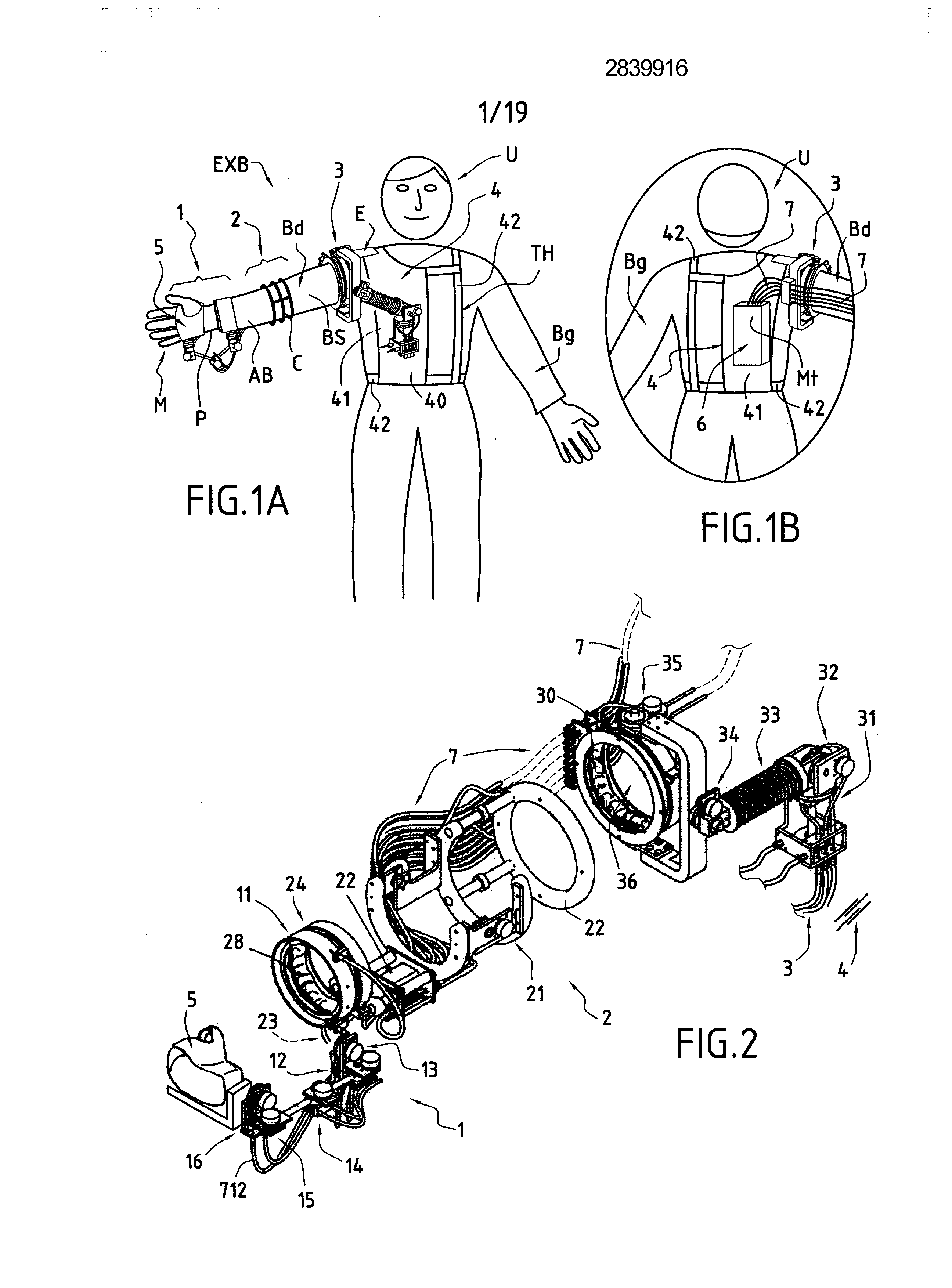
EXOSQUELETTE FOR HUMAN ARM, IN PARTICULAR FOR SPACE APPLICATIONS
A exoskeleton for a human arm. The invention is more particularly, although not exclusively, in the spatial technologies. It is first useful to recall the meaning of the term "exoskeleton", more particularly as used in the invention. "Exoskeletons" is a term used originally in the field of biology to designate the outer supporting structure of an animal. For example, arthropods have a outer exoskeleton chitin instead of a skeleton inside. Recently, the term has also been associated with structural devices for attachment around members of people. More recently still, a new class of devices has been added to the family exoskeletons: it is mechanisms used, for example, to increase the performance of human execution, in robotics or in interactions virtual reality. Other uses of these mechanisms will be detailed below. To fix the ideas, is will be effected in the following in the preferred application of the invention, in other words the spatial application technologies. More specifically further, consider is the case of the remote control of a humanoid robot type working outside of a space station, for example the International space station. It can be, in this framework, the robot called " [...]" which is expected to provide a very precise average and skillfully intervention for inspection, maintenance and repair of the equipment in highly hostile environment of the space. The robot has three arms kinematically similar to the human arm (i.e. with seven degrees of freedom). During the major portion of the time, the robot is programmed to perform predetermined tasks, but in some cases the robot needs to be controlled: -either by astronauts within the space station, or -either directly by operators remaining on earth. In both cases, the need for very precise manipulations has imposed the use of immersion techniques. To this end, the operator carries video glasses, gloves and a force feedback or exoskeleton (s) to experience sensations arm of the robot, i.e. those that would be experienced if it had performed the tasks performed by the robot. Exoskeleton The need to create a compatible with operators or astronauts is not without constraints. Here it is necessary to perform a light system (typically less than 5 kg), compact and easy to carry. The exoskeletons of the prior art generally suffer from various disadvantages and/or deficiencies, such as the following: -Untreatable feel all movements of the human arm and forces and torques feedback, without limiting the normal range of human motion arm. It is also necessary to obtain information on the position of the shoulder, elbow and wrist. -Difficulty produce a system actually "portable", which means that the movements of the operator should not be limited in use (rotation around an object, lean, walk, etc). -Application limited, which, for example, does not use the same exoskeleton, without substantial modification, for a high percentage of the male population, typically in a range covering 5% to 95%. More specifically, the human exoskeletons arm must overcome a main problem, in other words the mimicking of the kinematic joints complex human shoulder, elbow and wrist. The difficulty in the simulated results from the fact that these joints are closely wrapped, with their rotational axes moving with the changing posture of the arm. Exoskeletons The according to the state of the art, are endeavoured approach the problem of the shoulder through the implementation of a mechanism which rests on top rear of the human shoulder. Imperfections of this approach can be found within the footprint and the mass of the mechanism. This weighs of also on the arm. For the wrist, massive solutions also have been used. In general, there is also that, in the exoskeleton known, the complex kinematic joints of the human arm are simplified and-like joints to a single degree of freedom, hereinafter referred to as "DOF" (for "Degree Of Freedom", according to the terminology commonly used Anglo-Saxon) for the purpose of simplification of the description. The disadvantage of this solution is that the normal movement of the arms, called the "master" (that imposes the actions) is disturbed and a feeling of comfort, during operation of the arms, called the "slave" (force feedback) is not possible. Without whether exhaustive, is can now briefly describing some known solutions and show their boundaries. U.S. Patent US 4,575 297 The A (Hans Richter) described a robot having a chest plate, arm an upper limb, a lower limb of arms having finger units and in which the human limbs are inserted. A human operator, to which such robot limbs are attached, sits on a support structure such as a mobile chair. Members robot, their lengths, the joints between the members and the common axes correspond to those of the human operator. Each joint sensor device is associated with a hydraulic motor. Robotic The shoulder portion is limited to movement about two axes. Another axis permits flexing or extension of elbow. A axis parallel to the axis of the forearm allows rotation of the forearm. On the wrist, a swivel connection, which is parallel to the articulated joint of the elbow, provides the means of a wrist human motion. Exoskeleton The mechanism taught by the aforementioned Patent the kinematics normal copy of a human arm. Each joint actuated is controlled by hydraulic cylinders, which are directly mounted adjacent joints. The range of motion permitted is relatively limited. In particular, without repercussions movement is not possible. U.S. Patent US 5,967580 The A (Mark E. [...] ) is related to a pair of links connected and force generating means for their use in slave robotic systems. The patent is related to a mechanical manipulator anthropomorphic, providing some of the capabilities of a human chest and of the possibilities of movement similar to that of the chest, shoulder, arm, wrist and hand of a human. Again, the kinematic system of the robot described in the aforementioned patent resembles the kinematic structure of a human arm. As a result, it is desired to provide a mechanical manipulator resembling the human thorax upper and arm, and may be provided with possibility of movement substantially equivalent to those of the chest and the human upper arm. A mechanical structure that provides the means for engaging the hands of an operator. A mechanism anvil exoskeleton can be used as to control the slave robot, but is not optimized for such use as such. The can provide data from tactile force feedback only to the portion of the exoskeleton equivalent to the hand. Both mechanisms are equivalent to the upper structure member in terms of human kinematic (parameters of the members and joints). Each axis of rotation is directly controlled by the linear motors to direct current. Only a very limited range of normal human movements of arm may be covered with the exoskeleton mechanism described. As described above, the force feedback is only possible on the human hand, a feature being the main object of this patent. U.S. Patent US 6,301526 The A (Sang Kim and Mun al.) describes essentially a device having a function of feedback force and which is mounted on a human arm. This may return feedback of delivery limit operation by using the engine brakes. The main device is a daisy chain, serial type, fixed on the back of an operator. Second and third combining means are secured above and below the bend, as well as a fourth combining means is fixed on the rear part of the hand. Exoskeleton Seven axes have electrical brake units to generate torques. Position determination units, and units for amplifying the coupled, are associated with the actuator units. The base of the kinematic chain is fastened on the back of the operator and low on the chest. Movement exoskeleton can only be influenced by electric brakes passive, that may only be used to mitigate the normal movements of the human arm. The international patent application WO 95/32842 Α2 (AN, Bin) provides a system that has the same degree of freedom that the human arm, and thus must be tightly attached to the human arm. The system is also kinematically equivalent to the arm of an operator. The exoskeleton is attached to the back of the operator and any component which forms interface with the human body is adjustable. As a result, any misalignment between the operator and the system imposes kinematic constraints of human joints and cause discomfort and a large discomfort for a normal anatomical motion. This invention primarily concerns the problem of securing to the operator, which problem has been solved with the particular design features. Kinematic The is limited to only five degrees of freedom. The movements of the shoulder belt, as the movements of the wrist, are never discernible or controllable. Each axis is actuated directly by an engine device for direct current, which is mounted near a common axis suitable. The kinematic structure very simplified, many of the components are to be considered to be set. The base of the exoskeleton is fixed to an upper portion of the back of the operator. Novel exoskeletons of known art, some just described, have significant limitations and are not able to respond fully to the needs which manifest, in particular for space applications. Exoskeletons The known in prior art are, for most, based on a mechanism which is intended to mimic or approximate best of the kinematics of the human limbs. Finally, emerge as the description of the invention which will follow, exoskeletons the mechanisms according to the prior art have important structural differences with the mechanism provided in the invention. The aim of the invention is, both, to the disadvantages of the prior art, and some of which have just been recalled, and to meet the needs which manifest, and which are also biased. The invention binds to an exoskeleton for a human arm having, in particular, all degrees of freedom thereof, light in weight, portable, because not limiting the motion of the operator, adaptable to a large percentage of the population, without substantial change, which experience all movements of the human arm, does not limit the natural range of motion, and is comfortable. For this purpose, and conveniently, the structure of an exoskeleton according to the invention has the following essential characteristics: The exoskeleton arm according to the invention is similar, in terms of its support base, to one half of a weave. It comprises two rigid plates chest (front and back) and a hinged handle. The breast plates are attached to the operator's chest by straps or equivalents any suitable means. The front plate serves as a structural base to of a jointed chain which articulates the handle. It provides a fixed reference for any movement of the exoskeleton. The back plate supports motors that move the joints of handle. Motors and joints are connected by a series of flexible tendons operate. The exoskeleton has several advantageous technical characteristics. In a first important feature, the kinematics own to an exoskeleton according to the invention is specifically designed. There is no attempt to mimic the kinematics of the shoulder, elbow and/or human wrist. Any on the contrary, a kinematic chain alternative, offering the same freedom of movement, is arranged parallel to the human joints. Human joints The chain and the form a closed kinematic loop which: -for the shoulder begins to the fastener of the arm (to the sternum), extends over the joints and ends and [...] scapulo-clavicula and ends in the middle of the humerus; -elbow begins in the middle of the humerus and ends in the middle of the forearm; and -wrist begins in the middle of the forearm and ends in the middle of the palm. Although the parallel kinematic of the exoskeleton is different from that of the arm, each pose human joints can be clearly determined by the corresponding posture of the kinematic chain exoskeleton. The advantages of such an approach are many, and can be summarized as follows: The weight of the system is not carried by the arm but by the chest. The full range of movement of shoulder, elbow and wrist is possible. The joints themselves are simpler and more reduced It is not necessary to align axes human joints with those of the exoskeleton: thus, no long and complex fitting procedure is required before that the exoskeleton is operational. The base of the exoskeleton is a part of the human body. Therefore, the exoskeleton can be configured as a portable system that provides more flexibility for the general movement of the operator. By using a portable controller exoskeleton, remote controls weightless, or for the least in micro-gravity, are very simplified because no resultant force on the body of the operator will not cause move away from the control station. As example, when using joystick feedback force, type "joysticks" (according to the Anglo-Saxon terminology), create forces thereof against the body of the astronaut, which repel the away from the handle. Therefore, it is to be attached at an appropriate place and its operational possibilities are thus limited. A second important feature is that all the joints actuated in the exoskeleton (i.e., non-passive) are controlled by transmissions cable tendon. In the prior art, usually is used to electrical driving members directly mounted on the exoskeleton. These arrangements make the exoskeleton bulky, heavy and require a large number of control units for that it remains compatible with a high weight. Tendons The use according to the invention allows placement the control units on a back plate of the exoskeleton. The weight of the drivers is thus carried by the chest. The result is an arm extremely light which can be controlled by smaller actuators. A third important feature relates to the possible adaptation of the exoskeleton according the invention to different human subjects. Indeed, its specific structural characteristics, which will be detailed herein enable the possible adaptation of the master arm to practically any human subject (percentage range above). The adjustments required for adapting the exoskeleton can be performed while carrying the same, and are limited typically to tighten two screw or equivalent means, as also will be shown below. The invention has for its main object an exoskeleton arm for acquiring data representative of movement of the arm link of a human operator by means of measuring sensors and applying feedback to said joints forces and/or torques using activation units associated with at least a portion of said joints, characterized in that it comprises a first device having the conformation of a handle, to be pulled over at least one of said arms, to form a drive train of joints positioned in parallel to said arm link, said device comprising a first subset of said exoskeleton shoulder comprising a first determined number of joints associated with the shoulder joints said operator, a second subset of said exoskeleton elbow including a second determined number of joints associated with the elbow joints said operator and a third subset of said exoskeleton wrist comprising a third determined number of hinges associated with the hinges wrist of the operator, and in that said activation units are controlled by flexible tendons running along said subsets, said first to third sub-assemblies being mechanically disassociated to be individually controlled by said flexible tendons. The invention also relates to the application of an exoskeleton arm to the remote control of a humanoid robot type working outside of a space station spatial with arms and artificial performing tasks under the control of a human operator, said exoskeleton arm being fitted onto at least one of its arms, said robot receiving data forcing executing movements in one-to-one relationship with movements of said arm and transmitting data forcing said feedback executing movements to all or a portion of said hinges of said exoskeleton arm and resulting in corresponding movement of said arm. The invention will now be described in more detail by referring to the accompanying drawings, of which: figures 1A and 1B schematically illustrate an example embodiment of an exoskeleton arm according to the invention carried by an operator, for the front and back, respectively; figure 2 is a view illustrating the burst three main subassemblies of an exoskeleton according to a preferred embodiment of the invention: the subsets of wrist, elbow and shoulder, respectively; figure 3A illustrates in more detail the subset of wrist of the exoskeleton of Figure 2, in front view, carried by the hand of an operator; figure 3B is a schematic representation, in three dimensions, illustrating the different joints associated with the subset of wrist of the exoskeleton of Figure 3A and their axes of rotation; figures 3C1 3C3 to illustrate a first member of the subset of wrist of the exoskeleton of Figure 3A, three-dimensional, in side view and a cross section of the figure 3C2, respectively; 3d3 figures 3D1 to illustrate a first member of the subset of wrist of the exoskeleton of Figure 3A, three-dimensional, when viewed from above and a ^ cutting of Figure 3D2, respectively; figures 3E1 3E3 to illustrate a third member of the subset of wrist of the exoskeleton of Figure 3A, three-dimensional, in side view and a cross section of the figure 3E2, respectively; the 3F3 figures 3F1 to illustrate a fourth member of the subset of wrist of the exoskeleton of Figure 3A, three-dimensional, in plan view and a cross section of the figure 3F2, respectively; figures 3G1 3G3 to illustrate a fifth member of the subset of wrist of the exoskeleton of Figure 3A, three-dimensional, in side view and a cross section of the figure 3G2, respectively; figures 3:001 3:003 to illustrate a sixth member of the subset of wrist of the exoskeleton of Figure 3A, three-dimensional, in front view and a cross section of the figure 3:002, respectively; figure 4A illustrates in more detail the subset bend the exoskeleton of Figure 2, in the space in front view, threaded on the arm of an operator and attached to its bend; figure 4B is a schematic representation, in three dimensions, illustrating the different joints associated with the subset of bend of the exoskeleton of Figure 4A, and their axes of rotation; figures 4C1 4C2 and illustrate in more detail, in side and top views respectively, the beam tendons and the precharge unit due sub-elbow assembly figures 3A and 3B; figures 4D1 4D3 and illustrate in more detail, the members of one of the links of the subset of bend of the exoskeleton figures 4A and 4B, in side and top views respectively, three-dimensional, in plan and a cross section of the figure 4D2, respectively; figures 5A and 5B illustrate in more detail the subset of shoulder of the exoskeleton of Figure 2, threaded on the arm of an operator and attached to its shoulder, to three-quarters top and front view, respectively; figure 5C is a schematic representation, in three dimensions, illustrating the different joints associated with the subset of shoulder of the exoskeleton figures 5A and 5B, and their axes of rotation; figure 5D illustrates, as viewed from the rear, the pre-tensioner mechanism tendons associated with the subset of shoulder of the exoskeleton figures 5A and 5B; 5e3 figures 5E1 to illustrate in more detail a first member of the subset of wrist of the exoskeleton figures 5A to 5D, three-dimensional, in plan and a cross section of the figure 5E2, respectively; figures 5F1 5F4 to illustrate in more detail a second member of the subset of wrist of the exoskeleton figures 5A to 5D, consisting of a telescopic joint, to the elongated state, in side view, and in section, and to the elongated state, in side view and cross-section, respectively; -figure 5F5 illustrates a detail of the telescopic joint figures [...] 5F4; figures 5G1 to 5G3 illustrate in more detail a third member of the subset of wrist of the exoskeleton figures 5A to 5D, three-dimensional, in plan and a cross section of the figure 5G2, respectively; figures 5:001 5:002 to illustrate in more detail a third member of the subset of wrist of the exoskeleton figures 5A to 5D, comprising an airbag, three-dimensional and in section, respectively; figures 6A to 6C illustrate schematically an activation mechanism for joints of the exoskeleton of the invention via tendons cable figure 6D illustrates schematically the actuating mechanism of the telescopic joint to 5F5 figures 5F1; and figures 7A and 7B illustrate, in the sagittal section, members fixations grinding tool for the arm and the forearm, respectively. In the following, as has been indicated and not limited to anything in the range, will be effected is below in the context of the preferred application of the invention, i.e. in the case of remote control operation by an operator (a astronaut for example) of a robot spatial, humanoid type working outside of a space station, the operator carrying an exoskeleton arm according to the invention. The robot, as such, is not directly involved in the invention and has not been shown in Figures. In well known, for applications of this type, is provided usually data communications between the robot and a fixed station, in the space station and/or the earth, or directly between the robot and a data processing system associated with the exoskeleton. Any means can be used two-way data transmission, advantageously of radio transmitting/receiving means-electric. The data "forward" consist of instructions transmitted to the robot for the operating, in response to a particular movements that the operator makes the exoskeleton. The robot reproduces the movements of the exoskeleton. In the opposite direction, it sends data called of "feedback" allowing the operator to "feel physically" forces and torques experienced by the robot, and not only "visually", e.g. in tasks performed by the robot on a display screen. This feedback on the operator is very important, because it allows, for example, of precisely metering and forces above torques exerted by the remote controlled robot. A working example of an exoskeleton arm according to a preferred embodiment of the invention will now be described by reference to Figures to 7B 1A. On these Figures, the identical elements bear the same references and will not be re-only described as needed. Figures 1A and 1B schematically illustrate an example of exoskeleton arm As previously indicated, the exoskeleton arm On figures 1A and 1B, the sub-assemblies, 1 to 3, of the exoskeleton arm These three subsets, 1 to 3, form a kinematic chain, whose specific characteristics will be described below. The chain is represented in more detail in exploded in Figure 2. In another important feature of the invention, said the drive train, more specifically, by the subset of wrist 1, is attached to a glove 5 threaded to a hand or both, In accordance with another important feature of the invention, said the drive train, more specifically, by the subset of shoulder 3, is attached to the chest In a preferred embodiment, the support base 4, resembles a half of weave. It comprises two rigid plates chest: to 40 (figure 1A) and back 41 (figure 1B). The breast plates, 40 and 41, are attached to the chest of the operator U In accordance with another important feature of the invention, the different subsets, 1 to 3, of the drive train are connected. Beams of tendons type flexible cable 7 to actuate particular joints associated with the subsets 1 to 3, said "active" joints and are actuated in turn by motors In reality, flexible tendons are constituted by two types of separate elements; cables themselves and claddings spiral guiding the cables on all or part of their lengths. On Figures, the visible portion of the beams 7 essentially comprises the sheaths. That is using the aforementioned active joints that forces and/or torques feedback can be printed in the exoskeleton arm There is two beams of different cables, arbitrarily called "beam [...] 1" and "beam No. 2". A first beam leads from the back of the operator In contrast, other joints, said "passive", however, being associated with motion sensors, allow the movements of the human arm The back plate 41 supports the aforementioned engines The housing 6 is in particular connected to the drive train, and more particularly to the subset of shoulder 3, by the beam tendons 7. They also comprise circuits for transmitting/receiving data and instruction communicating directly with the robot to be remotely controlled or via an intermediate station (not shown). The motors One will detail more accurately maintaining the drive train. In a whole, the master arm of the exoskeleton The joints are grouped, as recalled, in three subsets: the subset of wrist 1 (comprising six "DOF"). the subset of bend 2 (which includes four "DOF"); and the subset of shoulder 3 (comprising six "DOF") Figure 2 illustrates a split assembly of these three mechanisms, 1 to 3, connected by a bundle of flexible tendons 7. According one of the essential features of the invention, the master arm is not designed to mimic the human joints arrangement, but to connect them by a kinematic chain alternately arranged link above the human limb: One will now describe in more detail the three subassemblies, 1 to 3, of the kinematic chain the exoskeleton arm Figures 5A and 5B illustrate the subset of shoulder 3, in front view and a three-quarters high, respectively. On these Figures, the head of the operator The subassembly 3 includes six pivot pins, five of the type known as a pivot and said prismatic type. The figure 5C is an isometric view illustrating, in three dimensions, the relative positions of these six axes, referenced A31 to A36, for a particular posture C operator of the bend of the The subset 3 is adapted to perform the same movements that those of the human shoulder E, although the five "DOF" human shoulder E are simulated by a mechanism to six "DOF". By these arrangements, the movement of the exoskeleton of shoulder 3 is limited, or amplitude or dexterity. The base of the exoskeleton of shoulder 3 provides the complete base of the link series of the exoskeleton arm The distal end of the mechanism 3 is situated at the base of the upper arm Except of the third articulation Their rotating is performed by pulling tendons that are secured by pulleys on the corresponding axes of the joints, as will be shown facing the following description. More specifically, these joints are each operated by a pair of tendons, which enables movements, either in a clockwise direction, or in an opposite direction. For a more detailed description of the system, is will refer to the Figures. The first joint The hinge "joint 33", prism type and A-axis33, is provided with a telescopic tube The spring A link fixed telescopic joint The link The fifth joint, Therefore, the fastening flange fixes the shaft 352 351 353 on the outer ring, and the fastening flange 355 354 fixes the shaft on the bottom of the ring 353, respectively. The two shafts pass through the ball bearings, which are held between the plate and the upper plate 344 343,345 and the plate and the top plate 346, respectively. The hinge A pair of tendons 736', from the back of the operator The three joints The figure 5D is an isometric view, as viewed from the rear, illustrating, three-dimensional, the system 8 pretensioning of the tendons of the beam 7. Through this system, tendons, which are guided within the sheaths, may be pre-tensioned by bringing the outer sheath under tension. The figure 6C describes more detail the general configuration of such a pre-charge unit 8. Each pre-charge unit in the design of the exoskeleton A general description of the components involved and their function will now be provided. A rigid frame, which establishes a fixed reference, hereinafter referred to as The five "DOF" of the human arm and six "DOF" the subset of exoskeleton of shoulder 3 form a closed kinematic loop with the following properties: -the full range of movements of the human shoulder £can be performed; and -all human joints (even the scapulo-clavicular) can be detected and actuated. One will now describe in more detail the sub-base assembly 2, by reference to Figures to 4D3 4A. The figure 4A illustrates more specifically, as viewed from the rear, the subset of bend 2. This comprises four articulation axes. The figure 4B is an isometric view illustrating, in three dimensions, the relative positions of the four axes, A21 to A24, for a particular posture C operator of the bend of the On the left-hand side of figure 4A, is represented two telescopic tubes gemini, 200 and 202 respectively, adjustable in length, which provide the means for adapting the length of the exoskeleton to the upper arm The first ends of the telescoping tubes, 200 and 202, are secured to a ring-shaped part 204, surrounding the upper arm These two rings, which are connected by means of telescopic tubes, constitute a part of the adjusting unit. Two additional parts are connected to this unit: two plates base joint for the articulation The pre-load of the forearm 217 is secured to the hollow tubes 215 and 216 by means of screws. On the figure 4A, tendons which pass through the pre-charge unit are not represented. On figures 4C1 and 4C2, is represented the tendons of the wire harness 7 entering the pre-charge unit, tendons outgoing not shown. The link The pre-load carries a linear sensor 218, whose moving part is attached to a plate 223. The plate is fixed to the solid tubes, 221 and 222, by means of screws. Therefore, when the link The link Figures 4D1 4D3 and describe the members of the joint The mobile link on the joint The link child, The need for kinematic apparently complex, compared to the simplicity also exposed the elbow joint, is justified below. Indeed, cannot be considered by human joint elbow pure C as a hinge, in the sense that the position of the shaft oscillates during the movements. Therefore, use in an exoskeleton of a simple " DOF 1 common, to mimic the elbow bending cannot lead to accurate results and because of the friction in the mechanism, because the two axes of rotation does never coincide. It is therefore necessary to add the additional passive two joints above, The mechanism combined then accurate results for the elbow flexion C, even if the system is so very inaccurate. Overall, the system establishes a reference kinematic structure above the bend human C, from the upper arm One will now describe in more detail the subset of wrist 1 by reference to Figures to 3:003 3A. The figure 3A illustrates, in front view, the subset of wrist 1. This comprises six pivot pins, all type pivot. The figure 3B is an isometric view illustrating, in three dimensions, the relative positions of these six axes, to A16, for a particular posture Figures 3E1 3E2 and are used as reference for explaining the operation of the first joint of the wrist sub-assembly 1. Figures 3C1 3G3 to illustrate further views of the mechanism-assembled. The corresponding joints are referenced " The proximal end of the sub-assembly 1 is fitted on the forearm The link Further means of the link " The sectional view of the joint The hinge The distal end of the cylindrical beam 143 is held in a further cylindrical portion 144, which is attached to a shaft 145. The shaft 145 constitutes the mechanical axis of the passive articulation The distal end is attached to a glove of hard plastic 5, placed on the hand of the operator U The subset 1 is attached to the housing 50 of the glove 5 by any appropriate means (screw, etc), via a distal 54 associated with the hinge axis " The hinge Said base plate 160 is maintained at a second plate 161 to fix a shaft 162 orthogonal to the surfaces of the parts. The shaft 162 carries a ball bearing on the distal side, on which is attached the base plate 150 of the Briefly, the mobility of the handle subassembly can be detailed as follows: The three joints With the human skeletal structure and the fasteners on the human body the operator To understand how a torque is exerted to perform a wrist bending P, is shown in the isometric view shown in Figure 3B. The joints, To achieve these movements, the two joints, Since the human wrist P is an articulation ellipsoid and a ball joint, these five links alone cannot provide a optimal behaviour the mechanism during circumduction or any other combined movement. Therefore, the joint has been introduced in the drive train. The hinge Advantageously, all joints subset 1 are associated with sensors, Ca Ca12 to16 ( figures 3B) which measure the angles of rotation around the corresponding axes, Λ [...], [...], to A16. The data, results of the measurement, are transmitted, by any suitable means, to the reception systems localized e.g. in the space station, or directly in the housing 6 (figure 1B). Transmissions It can be wired or wireless (radio-transmission, etc). These aspects, per se, are well known to one skilled in the art and it is not necessary to detail further. As a result of these provisions that the sub-assembly 1 allows for free movements of the wrist P, without limit in any way the degree of mobility of the operator One will now describe in more detail the operation of the control unit of the hinges. Since it has been indicated, according to one of the important features of the invention, the drive torques of live hinges are remotely transmitted by using cords tendons 7', guided along the exoskeleton structure In a practical embodiment, are advantageously used, the tendons of the beam 7', of multicore cables, typically and 7x19 of 1 mm diameter. This choice enables minimize friction of curvature and allows loads of up to 50 nm. To efficiently transfer torques tendon using a transmission cable, the cables are to be subjected to forces to be pre-tensioned to half their operating load, is 25 nm in the example described. Figures [...], 6B and 6C schematically illustrate how a pair of tendons cable, arbitrarily referenced 700', actuates one of the active joints, of arbitrarily referenced A pulley, arbitrarily referenced On the figure 6A, the two parts and A ^ Of course, a torque in the opposite direction (clockwise) affect the movable part in its first state Tendon 700' are guided on the exoskeleton The figure 6C described in greater detail the mechanical units included along the path of a tendon, from an engine and terminating at a joint activated. The figure 6C describes the general case of activating the joints of rotation. Tendon 700 ', which are fixed to the pulleys Guide through the precharge unit, tendons 700' are guided by a sheath 700 leading to a motor unit ( Therefore, for carrying action of the activation unit, the motor is to It should be understood that the controller joint just described is located at active all the joints have been described previously. A special case of linear activation is comprehended by reference to Figure 6D which describes schematically the linear on the common joint prismatic The function of the pre-initial charge is identical to the functionality described herein as facing the figure 6C. The main difference resides in the activation unit. The linear articulation is operated by only one tendon 700', which is inserted at the center of the telescopic tubes After pass through the pre-charge unit, the tendon 700' and the sheath 700 reach the motor unit. The motor unit includes a reference plate M If the engine pulls the tendon 700', the plate One will now describe in more detail the manner of fixing to an operator To return, the exoskeleton complete In the fixations Figures 7A and 7B illustrate, in the sagittal section, the cushions inflatable annular subsets of shoulder 3 (cushion 30) and wrist or elbow 2 1 (cushion 28), respectively, also as shown in Figure 2. The annular inflatable cushions, 30 and 28, are inserted in two rings outer rigid, 31 and 240 respectively. Advantageously, inflatable annular these pads can be made of silicone rubber and may be inflated by pumps which can be off by clamps. When inflated, the rings create a slip-resistant binding between the human arm, In order to minimize the friction at each joint and thereby increase the efficiency of the overall system, with each axis is advantageously of ball bearings, for example the ball bearings 242 referenced in Figure [...]. Therefore, the human motion mechanisms follow each upper arm In one example of the practical realization of the exoskeleton arm The last interface to the human arm In view of the foregoing, there is easily that the invention achieves the goals that it is attached. The exoskeleton arm according to the invention provides, as it has been biased, many advantages, that it is not necessary to recall. This is due, on the one hand to the original design of the kinematics, which does not attempt to mimic the kinematics human. This is due, on the other hand, to the use of cable tendon to actuate the hinges. This is due to the implementation of airbags, allowing high adaptability of the exoskeleton, without the need for tedious procedure settings: adjusting two screw members or the like, located in the telescoping tubes, is typically sufficient to provide a match It should be clear however that the invention is not restricted to only those Exemplary embodiments explicitly described, particularly in connection with Figures 1A to 7B. Also, although the invention has been described in its preferred application, in other words the remote control of a humanoid robot type working outside of a space station, it is clear that the invention is by no means limited to that application. Any on the contrary, it is applicable in many fields, and, but not limited to, in the following fields: remote control highly accurate real or virtual robots for nuclear operations, for operations of the type known as "offshore", for clearing, for manipulations of hazardous materials, for biological decontamination, etc; re-education of individuals with temporary alterations of the arm: the exoskeleton is used for passive gymnastics; actuation of passive prostheses for disabled persons, orders are performed by the voice or by transmitting nerve impulses; entertaining drive of the physical form: in addition to video glasses, the exoskeleton may provide the arm exercise a set of physical form; drive of the physical form of astronauts in orbit, in long-term mission: the biased use is similar to that above, but more precisely with the purpose of combating wasting of bone and muscle; increasing force for patients suffering from muscular deficiencies; realistic animation of virtual characters for the television industry and/or movies: movement of the arm of a character follows that of the moderator, providing a smoothly and very natural behavior; said immersion video games; teaching of the industrial robotics, for example for tasks and high-precision tasks to reduced scale, such as robotic assemblies for micro-electro-mechanical systems (said "MEMS" according to the Anglo-Saxon terminology) or technologies micro-and-Nano (said "MNT" according to the Anglo-Saxon terminology); and drive of astronauts in a virtual environment. The exoskeleton (EXB) includes a kinematic chain of parallel pivots on the pivoting of the human arm (Bd). It comprises a shoulder exoskeleton (3), a curved exoskeleton (2), and a hand exoskeleton (1). The main exoskeleton has six degrees of freedom. There is a support (4) carried by the thorax (TH) of the human operator (U), having a rigid front plate (40) and a rear rigid plate (41). The shoulder exoskeleton is fixed in its proximal extremity to the front plate, this forming a fixed reference for all movement of the exoskeleton, and the exoskeleton of the hand is fixed to a rigid glove (5) on the hand of the operator. The active flexing areas are controlled by flexible tendons of cables along the exoskeleton, these activated by control units disposed on the rear rigid plate. 1. Exoskeletons arm for acquiring data representative of movement of the arm link of a human operator by means of measuring sensors and applying feedback to said joints forces and/or torques using activation units associated with at least a portion of said joints, characterized in that it comprises a first device having the conformation of a handle, to be pulled over at least one of said arms, to form a drive train of joints positioned in parallel to said arm link, said device comprising a first subset of said exoskeleton shoulder comprising a first determined number of joints associated with the shoulder joints said operator, a second subset of said exoskeleton elbow including a second determined number of joints associated with the elbow joints said operator and a third subset of said exoskeleton wrist comprising a third determined number of hinges associated with the hinges wrist of the operator, and in that said activation units are controlled by flexible tendons running along said subsets, said first to third sub-assemblies being mechanically disassociated to be individually controlled by said flexible tendons. 2. Exoskeletons according to claim 1, characterized in that it comprises a second device, support, carried by the chest said operator, comprising a rigid plate front, said chest, and a rigid plate rear, said back, in that said shoulder exoskeleton is attached at its proximal end to said front plate, thereof provides a fixed reference for any movement of said exoskeleton, and in that said exoskeleton wrist is secured to its distal end to a hand of said operator. 3. Exoskeletons according to claim 2, characterized in that said flexible tendons comprise cables threaded in guide sheaths spiral and in that they are actuated by motorised control units disposed on said rigid plate back. 4. Exoskeletons according to claim 3, characterized in that the sum of the first, second and third numbers determined joints is equal to sixteen, so as to allow sixteen degrees of freedom. 5. Exoskeletons according to claim 4, characterized in that said shoulder exoskeleton comprises six joints each associated with an axis of rotation, and in that said first, second, fourth, fifth and sixth joints are of type and said third pivot joint is prism type. 6. Exoskeletons according to claim 5, characterized in that said shoulder exoskeleton comprises a first member providing said attachment to said rigid plate and chest associated with of the first and second joints type pivot. 7. Exoskeletons according to claim 6, characterized in that said shoulder exoskeleton comprises a second member with air bag threaded on the upper portion of said arm, so as to block said exoskeleton shoulder thereon, in that said air bag is enclosed in an annular piece disposed between the ends of the branches of a piece in the shape of "U", and in that said ends are associated with third and fourth type pivot joints. 8. Exoskeletons according to claim 7, characterized in that said shoulder exoskeleton comprises a third member with a telescopic tube surrounded by a pretensioning spring, in that said third member is attached by a first end, freely rotatable about the axis of said second joint, to said first member, and by a second end, at a point of the base of said "U", said attachment point forming the fifth type joint pivot, in that said third member forms said prismatic joint, and in that the said spring is actuated by a cable of said tension exerting a force thereon, to the compressing or the retract, in the direction of said force exerted. 9. Exoskeletons according to claim 5, characterized in that said first, second and sixth joints, pivot type, called active, are actuated by flexible tendons determined, and in that said fourth and fifth joints, type pivot, said passive, are actuated by any of said flexible tendons. 10. Exoskeletons according to claim 4, characterized in that said exoskeleton elbow includes four joints each associated with an axis of rotation, and in that said first, third and fourth joints are of type and said second pivot joint is prism type. 11. Exoskeletons according to claim 10, characterized in that said elbow exoskeleton comprising a first member having a first part, ring-shaped, and a second piece, horseshoe-shaped, secured to one another by telescoping tubes adjustable in length by means of a screw device, said first and second pieces being threaded above said bend, on the upper portion of said arm. 12. Exoskeletons according to claim 11, characterized in that said elbow exoskeleton comprises a second member having a third part, horseshoe-shaped, secured to said second part, horseshoe-shaped, by an intermediate part, said third part being threaded below said bend, on the forearm of said arm. 13. Exoskeletons according to claim 5, characterized in that said first and fourth joints, pivot type, called active, are actuated by flexible tendons determined, and in that the said second and third joints, type pivot, said passive, are actuated by any of said flexible tendons. 14. Exoskeletons according to claim 4, characterized in that said exoskeleton comprises six wrist joints each associated with an axis of rotation, and in that said first to sixth joints are of type pivot. 15. Exoskeletons according to claim 14, characterized in that exoskeleton wrist includes a first member with air bag mounted on a forearm said operator, near the hand, so as to block said exoskeleton wrist thereon, in that said air bag is enclosed in an annular part, and in that said first member is associated with said first joint. 16. Exoskeletons according to claim 15, characterized in that, said hand being inserted into a rigid glove, said exoskeleton wrist comprises a second member comprising a piece of rigid attachment to said glove. 17. Exoskeletons according to claim 16, characterized in that said rigid glove has openings leaving the free passage to the fingers of said hand and is provided with fastening means constituted by a woven fabric self-engaging. 18. Exoskeletons according to claim 16, characterized in that said wrist exoskeleton comprises a third member a mechanical linkage between said first and second members, in that said device comprises a fitting on said ring, said fastener being associated with said second joint, and first and second connecting rods articulated, at a first end, around an intermediate part, associated with said third joint, in that said first rod is secured, at a second end, to said fixing part at said ring, for free rotation about an axis associated with the third joint, in that said second rod is secured, at a second end, to said fastener on said glove rigid, for free rotation about an axis associated with said fifth joint, and in that said fastener to said rigid glove is further associated to said fifth and sixth joints. 19. Exoskeletons according to claim 14, characterized in that said first, second, fourth and sixth joints, called active, are actuated by flexible tendons determined, and in that the said third and fifth joints, said passive, are actuated by any of said flexible tendons. 20. Exoskeletons according to any one of claims 9,13 or 19, characterized in that said hinges comprise pulleys drive axis of rotation which coincide with the axes of the said hinges and in that said pulleys are driven in a clockwise direction or in the counterclockwise direction by a pair of flexible tendons, so as to induce corresponding rotational movement of the joint associated with said pulley. 21. Exoskeletons according to claim 3, characterized in that it comprises members pretensioning subjecting said flexible tendons an initial force of predetermined magnitude, fraction of a maximum value of load to be supported, and in that these pre-tensioning members are disposed on said shoulder exoskeleton. 22. Exoskeletons according to claim 21, characterized in that said pre-voltage comprise screws clamping/unclamping acting on the ends of said cable guide sheaths. 23. Exoskeletons according to claim 3, characterized in that said control units operating said flexible tendons are direct current motors disposed on said rigid plate back. 24. Exoskeletons according to claim 4, characterized in that said joints are provided with angle sensors measuring the rotation of the shafts associated with these joints. 25. Exoskeletons according to claim 2, characterized in that said breast plates and back of said support are attached to each other by straps fabric self-engaging. 26. Application of an exoskeleton arm according to any one of the preceding claims to the remote control of a humanoid robot type working outside of a space station spatial with arms and artificial performing tasks under the control of a human operator, said exoskeleton arm being fitted onto at least one of its arms, said robot receiving data forcing executing movements in one-to-one relationship with arm movements and transmitting data forcing said feedback executing movements to all or a portion of said hinges of said exoskeleton arm and resulting in corresponding movement of arm.