자동 슬라이딩 도어용 구동 시스템
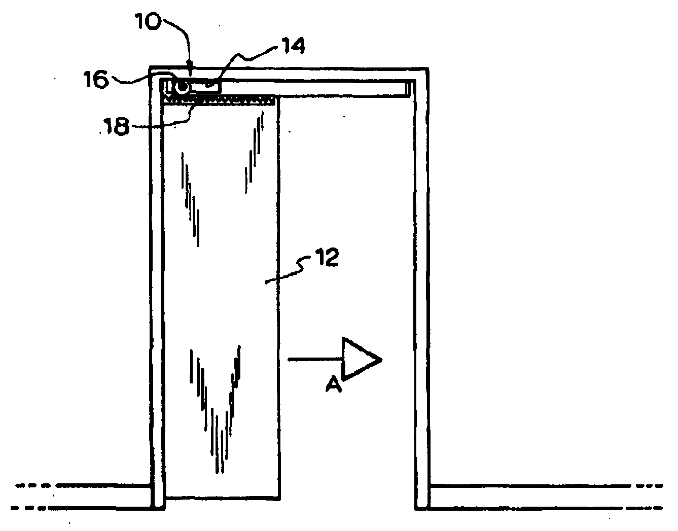
The present invention refers to a drive system for automatic sliding door are disclosed. The present invention refers to in addition driven system sliding door driving device whether a suitable are disclosed. Sliding door installed existing sliding door or window in the field styles or geometric irrespective of the structure or redirect (retrofitting) drive system has a general requirement can be [...] number flow tides. In addition, overload time wasted and expensive cost for repairing a cascaded systems since, automatic sliding door drive system level of the pressing has been. The purpose of the invention is useful alternative drive system number [...][...] meet said request number at least 30 to 60 seconds. According aspects of the present invention number 1, automatic sliding door system is ball number, said drive system is, Driver; and Number 1 or number 2 co-operates with corresponding rack associated with said door when said door of sliding movement in the direction connected to and adapted to cause a pinion; Said driver and said pinion is located is selectively attachable 2: is said 2 position, (A) causing said door of sliding movement in the direction number 1 number 1 position; (B) causing said door of sliding movement in the direction number 2 number 2 position are disclosed. Preferably, door to door frame formed along a top rail and 2 frame made glazing or panel. In the upper area of panel top rail is held in place by guard or glass number preferably. Guard generally ceiling attached to the substrate. More preferably driver comprises a motor or gear box. In a preferred embodiment, rack via a frangible connector glass or panels in the upper area of top rail configured to be coupled to received signals. This standard size frame by glazing with partition door on top rail formed on a runner (patio door) is referenced to a carriage suspended with guard attached to the cavity door (cavity door) is most suitable for the disclosed. The channel preferably adapted by a driver connector between a door over an interval. Each channel has L-shaped cross-section are disclosed. Optionally, channel of elongated cavity having an open end (open a-ended) can be. A drive system provides a channel one or more termination can be applied to zero and one or more cap. Preferably, each cap is fixed means in at least one screw can be formed like. Alternatively, when short partition door on top rails, rack side door frame or side door frame extending from the one or more instant (grab) can be attached to the door frame. Preferably, number 1 number 2 direction is the opposite direction to the matrix. In a preferred embodiment, driving system includes a connector that is complementary to and adapted to be fitted without using a tool member. Distance between the bottom part and driver door member is preferably adapted to concealer (concealer) connected are disclosed. Preferably coding device driver is bound to operate together. Preferably, coding device is a remote number as soon as possible following disclosed. Coding device may any sliding door 4 the mode of operation selected from the group consisting preferably manner. Number 1 (automatic) mode which is located in one or more sensors such that acts in response to a door opening or out can be sliding door. Number 2 (locking) mode inner locking mechanisms to the underside of the sliding door in the closed position comprising. Inner locking mechanism or motor can be associated with or essential elements. Preferably, inner locking mechanism remote number as soon as possible following disclosed. Number 3 (frame for) mode sliding door comprising Image is preserved. (FET (pet)) mode coding device is adapted to respond to performance number 4 of the sliding door to operate at one or more of the States both sides to each other. Preferably conveniently, coding a different coding device relative to another device connected to the moving object. This e.g., fly screen door on involving partition is most suitable for the disclosed. Preferably coding device may operate so as to enable the set consists of master and slave. Thus, operation of the door and partition on complementary fly screen can be synchronized. Coding device may beam reflected from an object sensor adapted to detect object including an activator (activator) which emits infrared emitter generating infrared beams and adapted to respond to received signals. Preferably, the misfortune mote hemp cloth shakes off door guard, holder adapted to be attached to wall or ceiling movably connected thereto. A pair of ratchet (ratchet bar) back plate holder extending therefrom having a predetermined wavelength. Preferably inclined ratchet teeth having a curved substrate. Generating infrared beams transmitted by the instructed to the operating zones in release of said in the embodiment angle misfortune mote hemp cloth defining other. Mobile is preferably adjust with ratchet pair misfortune mote hemp cloth. The misfortune mote hemp cloth shakes off on ratchet teeth which number of places where it is required by the selected pairs of inclined ball can be fixed. According to one aspect of the present invention number 2, driven system sliding door driving device whether a number is suitable to ball, Number 1 end and adapted to be pulled by a user At least one scale including region; and Selectively with respect to one scale and adapted to be detachably attached to the light sources and number 2, number 2 number 1 end said region is between to the lungs. Number 1 stage including a loop preferably adapted to be held by the user. The capacity against a particular drive system according to the scale selected, then comprise a drive system of the present invention number 1. Preferably, scale area of the at least partially Fixed to the loop portion and number 2 stage Hook portion consists of, or consists of vice-versa. Other attachment method can be used. In use, a user device such as the door handle is attached to the attachment means, and number 2 end attached to a desired scale, door number 1 to pull selected direction employing a substrate. When the desired end away from said scale during number 2, driving sliding door not adapted to index that in turn holds the drive system are disclosed. In this case, the user can be more powerful e.g. the entire driving system is selected. The inspiration device number 1 number 2 then driven system suitable for selectively driving sliding door are used to determine whether a. In order to more clearly understand properties of the present invention, one preferred embodiment of the present invention number will not are then described, this example does not only by Image, described by reference to a drawing appended will. In the embodiment of the present invention Figure 1 shows a side view of one preferred drive system as also along, mobile [...] lock door direction can be maximized. Figure 2 shows a door mounted so as to movable in the direction of drive system of Figure 1 also opposes are disclosed. In the embodiment of Figure 3 shows a perspective view of the present invention drive system as also partially magnifying, driver engine decodes pinion arranged in one position. Figure 4 shows a perspective view and partially magnifying for the driving system, engine driver and pinion arranged in a position different from the etched also of Figure 3. Figure 5 shows a short top rails also mounted on cross-section of the drive system of 3 or 4 door on partition also are disclosed. Figure 6 shows a top rail than on door 3 or 4 mounted on cross-section of the drive system of party also are disclosed. Figure 7 shows a cross-section of the drive system of 3 or 4 mounted in cavities formed on a door also are disclosed. Figure 8 shows a corresponding blind of sensors mounted thereon also cap are disclosed. Figure 9 shows a drive system of Figure 4 or 3 also adjusted rack mounted partition movement also focused on door apparatus of sensors mounted thereon are disclosed. Figure 10 2 diaphragm grams of coding configuration are disclosed. Figure 11 shows a drive system of Figure 1 shown associated with a side of misfortune mote hemp cloth under actuator of 2 are disclosed. Figure 12 shows a perspective view of Figure 11 of misfortune mote hemp cloth holder adapted for holding are disclosed. Figure 13 shows a perspective view of device in the embodiment of the present invention number 2 of which then also, driven system exhibits a cylindrical shape sliding [...] whether driving. Figure 14 shows a also sliding door of Figure 13 device applied to the front face of the disclosed. Of the present invention drive system is preferably designed to be specified that the will be dubbed inlater home. Large scale commercial building sliding door drive system for driving even more powerful motor, which require many different component of adaptation are disclosed. The reference 1 and 2 also, automatic sliding door (12) of the drive system (10) the driver (14) and pinion (16) comprises. Pinion (16) a door (12) related corresponding rack (18) when connected to operate together corresponding rack (18) to (also 1) with A indicated number 1 (closed) or reversibly B number 2 (reverse) direction (also 2) directed to one or more door (12) of sliding to induce motion other. At this time, the door closing direction is 2q2p (12) can be opened and closed. Driver (14) is not shown motor and gearbox having a predetermined wavelength. Also 3 and 4 as well as unreliable also, pinion (16) optionally 2 is located in driver (14) attachable to disclosed. As shown in fig. 3, number 1 position number 1 A direction door (12) are used to cause sliding movement. On the contrary, as shown in the direction of the panel number 2 position number 2 B 4 also causes sliding movement adapted thereto. Pinion (16) the driver (14) number to which ball hollow (15) is received in a shaft (13) with each other. Bolt (not shown) a pinion (16) axis (13) the hollow (15) in place in number to ensure other. Also 5 to 7 and 9 also verifies the, in the embodiment other door (12) is top rail (24 (5 also), 26 (6 also) or 28 (also 9)) and two side door frame (30, 32, also 9) glazing formed by frame (22) or panel (20) made of vehicle from the outside. In the upper area of panel (also 7) (34,) or glass (22, also 5, 6 and 9) top rail (24, 26 or 28) is formed as the (36, 38 or 40) being maintained in place by respective number. Guard (36, 38 or 40) is ceiling (42) attached to the substrate. Also with reference to the 5 and 6, partition on door (44, 46) are all partially top rail (24, 26) formed by respective frame glazing (22) having a predetermined wavelength. In both two in the embodiment, rack (18) is glass via a frangible connector (22) top rail (24 or 26) is connected thereto. Connector generally L shaped cross section and having a channel (48) form. Channel (48) on the partition door (44, 46) and driver (14) over an interval between 2000. Channel (48) in addition the open end extending cavity (50) two groove (52, 54) contact with each other. On partition door (44, also 5) top rail (24) on the partition door (46) top rail (26) can be shorter than the door frame. Said reasons, channel (48) with a top rail (24) when is brief (5 also), vertical walls (56) arranged to be triggered, top rail (24) greater (6 also), inversely disposed thereon. Also 5 and 6 also shown in channel (48) on the partition door (44, 46) in storage suitable, normal size top rail frame formed by each glazing (22) contact with each other. 7 Also consults the, drive system (10) panel (20) consisting of a cavity door (58) is connected thereto. In said in the embodiment, rack (18) channel (64) order to turn on the connector in the form of (20) in the upper area of (34) connected to, channel (64) also present in the auditory canal 5 and 6 open end cavity (50) is etched out number does not exist. Cavity door (58) includes a guard attached to the runner (62) is referenced to a carriage suspended (60) supported by the substrate. As shown in 8 and 9 also, cap (66) channel (64) end (68, 70) adapted to each encoded ball number. Cap (66) channel (64) groove (52, 54, also 5 and 6) that engages a projection (72, 74) contact with each other. Cap (66) channel (48, also 5 and 6) end of KIPO the will fit will be disclosed. 8 Also well as shown, cap (66) by the screw (not shown) such as a fastening means for the receiving hole (76) with each other. Cap (66) is glass (22) or right angle can be structured such that it is in parallel to one another. 8 And 9 may also reference a, partition on door (78) in the embodiment is of very short top rail (28) having a frame with each other. In this case, rack (64) at one end of side door frame (30) is attached to the, other one end side door frame (32) extending from the instant door frame (80) attached to the substrate. Packer (82, also 8) is attached to the cap (66) and door frame (30) between the ball number encoded. Packer (82) in addition hole (84) with screw receiving substrate. Packer (82) is attached to the cap (66) and tightly coupled rack (64) the door frame (30) connected to ensure that substrate. The reference also 10, driver (14) includes a remotely adjustable coding device (92) coupled with each other to operate together. Coding device (92) door (12) is to operate are four mode one can. Number 1 (automatic) mode in response to one or more sensors located or out of the door will operate by means of a sliding door. Number 2 (locking) mode door (12) in the extended position to the underside of the closed by the internal locking mechanism comprising. Inner locking mechanism associated with the key components is formed or motor engine can be expected. The remote locking mechanism employed in magnets remote unit number number of known. Number 3 (frame for) mode door (12) comprising maintaining in open position. Number 4 (FET) adapted to respond to the performance of a coding mode device including a groove, sliding door (12) to operate at one or more of the States as follows. In this case, coding the device (94) associated with programmed to access or sensor (94) within a heat radiation detectable by object is reacted with each other. Coding device (92) is carried out manually or remote number the device (98) by on/off adjustable mode selector switch (96) contact with each other. Sensor (94) is operated in an idle state or a stationary thermal radiation during or detects an object can react or can be removing. This e.g., FET region at the entrance for stopping WIPO. Selected areas range in the event of a sensor (94) defined by beams emitted from one or more. In addition bottom pressure sensor (100), active IR detector and motion sensor (102) such as other forms of sensor coding device (92) associated to are taken into account. Drive system (10) to fit existing of sliding door can easily fly screen design re setting is, for example, summer, as original door back later wishes are confirmed each other. In addition also 10 as shown, coding device (92) connected to other moving object another coding device (104) can be associated. This e.g., fly screen door on involving partition is most suitable for the disclosed. Coding device (92, 104) to fix the die master and slave is set consists of manner. As said, partition on door (12) and a supplemental fly screen (not shown) can be the movement of the synchronization. Each master and slave switch (106, 108) manually using, or remote number the device (98) electrically using, capable of active or deactivated. In operation, command transmission communication channel established between directional master slave receiver with respect with each other. In order to ensure sink as well as retaining the door operation, door and fly screen used and all sensors the wireless communication or wired communication interface is continued remote number by one master coding device (92) must be associated with, 'open' and 'closed' command is not the master can be known by both number should be. The reference 11 and 12 also, coding device (92) is adapted to detecting beam generating infrared beams reflected from an object sensor (122) and emitting infrared emitter object including an activator (110) designed to response. Each activator (110,112) includes a wall (16, also 11) attached to the holder (114, also 12) movably connected thereto. Holder (114) is as shown in (118) extending from a pair of curved ratchet back plate (120) having a predetermined wavelength. As shown in fig. 11, generating infrared beams (122) release angle Is an activator (110,112) indicated by the direction of adjustable, defining the operating zones to be coated. An activator (110,112) the movement of the ratchet (120) is adjusted so that with manual or electrically adjusted pair can be. An activator (110, 112) includes a ratchet (120) inclined teeth which number on ball (124) by the pairs of secured in selected locations. Vertical beam angle is used (i.e., When 0 is also), an activator (110,112) is present merely by changing the un number doorway obstacle and therefore will not maintain a specific trigger for door closure preventing any obstacle 'safety curtain' will form. The reference also 13, device (26) driving a drive system suitable for whether a belt in the form of sliding door. Belt (26) is number 1 stage (128), number 2 stage (130) number 1 and number 2 area positioned between end (132) comprises. Number 1 stage (128) held by user configured to loop (134) contact with each other. Region (132) includes a plurality of scale (136) with some of which label display in the nanometer range. Number 2 stage (130) is optionally releasably scale (136) are affixed to a selected one of the. Scale region (132) is Consists of the loop portion of the antenna. Number 2 end of a hook portion (130) secured to. However said configuration is the possibility of being exchanged be vice versa. The reference also 14, in use, the user first belt (26) forms (140) handle (138) attachment means are attached to the form. Number 2 stage (130) is then attached to a desired scale are disclosed. When the user number 1 stage (128) direction selected door (140) a used to pull each other. In said number 2 stage (130) separated from scale if desired, this door (140) is too heavy or too much friction system exists, a load indicated by the selected scale processing driven system sliding door (140) not adapted as an index for driving are disclosed. In this case, e.g. the user selects system is used together diffuse to the driving system of more powerful specifications. The number of the present invention has been discussed in greater detail below in the embodiment is preferably several, out-of-one skilled art drive system and an instruction device number of advantages at least below [...] ms. frames are: 1. The present invention refers to installation and application are easy copyright 2000. 2. Styles or sliding direction used to sliding door can be installed. 3. Also fly screen can be synchronizing the opening and closing of door and partition. 4. The detection region can be easily selected. 5. A drive system overload or improper selection indicating device preventing substrate. One skilled are the specification specified just described invention are described rather than deformation and plan will understand. The device must be taken into account in the mental and in all deformation and change of the invention, techniques of the present invention will be determined from the movement of the matter to be protected against. A driving system for an automatic sliding door includes a driver and a rack and pinion mechanism. The pinion is selectively attachable to the driver in a first position to cause sliding movement of the door in the first direction and in a second position to cause sliding movement of the door in the second direction. A device for indicating whether a driving system is suitable for driving a sliding door includes a first end, a region including one or more calibrations; and a second end. The first end is adapted to be pulled by a user. The second end is adapted to be selectively and detachably attached to one of the calibrations. The region is located between the first end and the second end. Automatic sliding door system, said drive system is, hollow having a driver, said driver is constructed to selectively attachable door frame 2 located in one, position number 1 and number 2 position number 1 sliding door driver that are aligned with edge position number 2 sliding door driver that are aligned with and edge position, the edge number 1 number 2 edge combat, driver; and axis with the pinion, said rack number 1 or number 2 related to cooperate with corresponding door direction adapted to cause movement of sliding door direction when connected, said 2 is selectively attached and located in said driver pinion, is located in said 2, (a) position number 1, number 1 direction to move said sliding door, hollow driver from a side of a shaft that is inserted into the, position number 2 (b), number 2 direction to move said sliding door, other side of the driver from a non-inserted into the hollow shaft, a drive system for automatic sliding door. According to Claim 1, said door panel or top rail and 2 upper region of the sliding door along a frame formed by glazing made, a drive system for automatic sliding door. According to Claim 1 or Claim 2, including said driver motor and gear box, a drive system for automatic sliding door. According to Claim 2, further comprising a connector, said connector through said rack in the upper area of said panel or glass configured to top rail, a drive system for automatic sliding door. According to Claim 4, said connector over an interval between said driver and said door and configured to channel, channel extension cavity having an open end and L-shaped in cross-section, a drive system for automatic sliding door. According to Claim 5, said part of the at least one capping agent that is configured to channel one or more tailored including, a drive system for automatic sliding door. According to Claim 4, further comprising a connector configured to fit within said member, said member adapted to connect to said display device and said distance between the door to the lower end, a drive system for automatic sliding door. According to Claim 1, said driver as soon as possible following coding device which is connected to the remote number, a drive system for automatic sliding door. According to Claim 8, said four modes hereinafter said coding device may be operated by a sliding door can be any selected one of a mode, said mode, said sliding door sensor acts in response to one or more number 1 adapted to number 1 mode; said sliding door is moved into its closed position to sufficiently enlarge the number 2 mode; said sliding door is opened and adapted to be retained in an active position number 3 mode; and said coding device is detectable by a sensor number 2 in response said sliding door is configured of object [chul presently said number 1, number 2 and number 3 mode including operating in at least one of the mode number 4 mode, a drive system for automatic sliding door. According to Claim 8, other coding device communicating with said coding device may connected to another moving object, a drive system for automatic sliding door. According to Claim 10, said coding device may said sliding door and said other moving object using synchronized motion disclosing for master and slave can be set that is configured to operate, a drive system for automatic sliding door. Back number Back number Back number Back number Back number Back number Back number Back number Back number Back number Back number Back number Back number Back number Back number