Torsional anomalies detection system
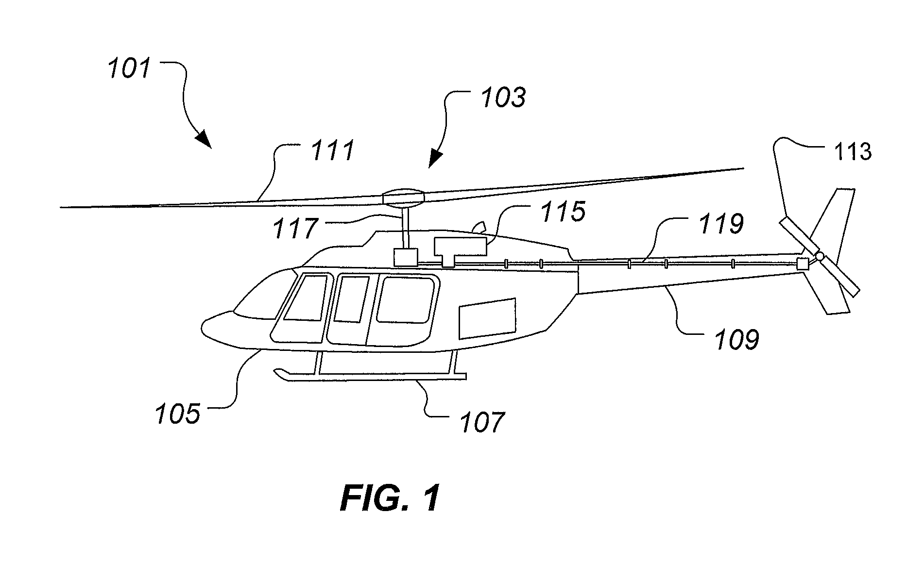
Technical Field The system of the present application relates in general to the field of drive system health monitoring, and relates specifically to the drive systems rotational oscillations and torsional oscillations and steady windup and detection of mechanical anomalies indicated by these changes in rotational oscillations and torsional oscillations and steady windup of a series of drive shafts. Description of Related Art Typically, in rotorcrafts parts are replaced based upon the number of hours flown. Therefore, parts are inspected and replaced regularly to insure the aircraft is flightworthy. Instrumentation systems, based upon accelerometers, provide fault detection of drive trains. As the aircraft parts fail, harmonic analysis of the vibratory patterns changes and indicates a failing part. However, accelerometers must be spread out along the length of the drive train as vibrations resulting from faulty parts are generally localized to the faulty part. Accelerometers must be regularly calibrated to verify their output requiring additional maintenance. Hence, there is a need for a method and apparatus for fault detection in a tail rotor drive shaft without accelerometers. The novel features believed characteristic of the system of the present application are set forth in the appended claims. However, the system itself, as well as, a preferred mode of use, and further objectives and advantages thereof, will best be understood by reference to the following detailed description when read in conjunction with the accompanying drawings, wherein: While the system of the present application is susceptible to various modifications and alternative forms, specific embodiments thereof have been shown by way of example in the drawings and are herein described in detail. It should be understood, however, that the description herein of specific embodiments is not intended to limit the system to the particular forms disclosed, but on the contrary, the intention is to cover all modifications, equivalents, and alternatives falling within the spirit and scope of the present application as defined by the appended claims. Illustrative embodiments of the system of the present application are described below. In the interest of clarity, not all features of an actual implementation are described in this specification. It will of course be appreciated that in the development of any such actual embodiment, numerous implementation-specific decisions must be made to achieve the developer's specific goals, such as compliance with system-related and business-related constraints, which will vary from one implementation to another. Moreover, it will be appreciated that such a development effort might be complex and time-consuming but would nevertheless be a routine undertaking for those of ordinary skill in the art having the benefit of this disclosure. In the specification, reference may be made to the spatial relationships between various components and to the spatial orientation of various aspects of components as the devices are depicted in the attached drawings. However, as will be recognized by those skilled in the art after a complete reading of the present application, the devices, members, apparatuses, etc. described herein may be positioned in any desired orientation. Thus, the use of terms such as “above,” “below,” “upper,” “lower,” or other like terms to describe a spatial relationship between various components or to describe the spatial orientation of aspects of such components should be understood to describe a relative relationship between the components or a spatial orientation of aspects of such components, respectively, as the device described herein may be oriented in any desired direction. A method and apparatus for determining failure diagnosis of drive systems of rotorcrafts through measuring the spectral characteristics of rotational oscillations and torsional oscillations and steady windup of a drive shaft. Mechanical anomalies of the drive system will alter the spectral characteristics of oscillations, both rotational and torsional, and steady windup as detected by a variable reluctance sensor in conjunction with a radial grating mounted on the drive shaft. The system produces a frequency spectrum based upon the output of the sensor and compares the frequency spectrum based upon the output of the sensor to a known good state and automatically detects oscillations that would indicate mechanical faults. The system provides a drive train and rotor system diagnostic tool to both the maintainer and the pilots. The system is configured to measure two types of oscillations in a drive system. First, the system measures torsional oscillations and steady wind-up along the drive train. Second, the system measures rotational oscillations along the drive train. Both types of oscillations can be used by the system to detect and indicate faults along the drive train. Referring to Referring now also to Sensor system 201 utilizes a first hanger bearing 121 and a second hanger bearing 123 as stationary sensor mounting platforms, while rotating sensor components are adjacently located on tail rotor drive shaft 119. Preferably, the stationary sensor mounting positions are located adjacent the circular targets. Tail rotor drive shaft 119 can include a plurality of drive shaft segments, such as drive shaft segment 119 First sensor assembly 203 is comprised of a first forward sensor 203 Second sensor assembly 205 is comprised of a first aft sensor 205 During operation, torque produced by engine 115 is transferred to tail rotor blades 113 via tail rotor drive shaft 119. The torque load on tail rotor drive shaft 119 can cause a variable torsional deflection. The torsional deflection can be referred to as a “wind-up” or “phase shift”, for example. Further, the torsional deflection can be the result of torsional loading in a variety of operational conditions. Sensor system 201 is configured to detect the difference in “phase shift” between the torsional deflections measured from first sensor assembly 203 and second sensor assembly 205. A processor 207 is configured to process the measurement data from sensor system 201. In one embodiment, processor 207 communicates the measurement data to a pilot of rotorcraft 101 in a display 209. More specifically, display 209 can provide a visual indication of real-time torque values, as well as past torque values, experienced in tail rotor drive shaft 119. Alternatively, the processor 207 communicated the measured data to a health and usage monitoring system (HUMS) 211. Referring now also to An algorithm stored in the processor compares measured windup, both steady and oscillatory, to a reference windup. Reference windup is determinable from either analytical models and/or empirical observations. Faults in the drive system and/or the rotor system, such as rubbing, looseness, or wear, will create a different windup. Additionally, transient conditions, such as a tail rotor bird strike, will also lead to different windups when compared to the reference windup. First sensor assembly is comprised of a first sensor 307, a second sensor 311, a support bracket 315, and radially shaped grating 317. First sensor 307 and second sensor 311 are preferably variable reluctance sensors or Hall effect sensors that reacts to grating 317 rotating in close proximity to the sensors. First sensor 307 and second sensor 311 are located 180 degrees apart from each other mounted to support bracket 315. Having two sensors in a sensor assembly improves accuracy, but a single sensor is sufficient in most locations. Support bracket 315 typically mounts to the airframe of the aircraft around the hanger bearing support Alternatively bracket 315 mounts to the hanger bearing support directly. First sensor 307 and second sensor 311 are axially adjusted till the tip of the sensors is typically 1-2 mm away from an outer edge of the radial grating 317. Radial grating 317 is typically ferrous and is mounted to the drive shaft coupling 321. Drive shaft coupling 321 couples the first drive shaft 304 and the second drive shaft 305. Referring now also to Referring now also to The system of the present application provides significant advantages, including: (1) providing diagnostic and fault detection information about the drive train, (2) measures windup and torque of the drive shaft, (3) does not require the use of wireless high frequency rotating instrumentation, and (4) does not use accelerometers. It is apparent that a system with significant advantages has been described and illustrated. Although the system of the present application is shown in a limited number of forms, it is not limited to just these forms, but is amenable to various changes and modifications without departing from the spirit thereof. A method and apparatus for determining failure diagnosis of drive systems of rotorcrafts through measuring the spectral characteristics of rotational oscillations and torsional oscillations and steady windup of a drive shaft. Mechanical anomalies of the drive system will alter the spectral characteristics of rotational oscillations and torsional oscillations and steady windup as detected by a pair of variable reluctance sensors in conjunction with a radial grating mounted on the drive shaft. 1. A system for detecting torsional anomalies of an aircraft during a failure, the aircraft having a first drive shaft and a second drive shaft, the system comprising:
a grating, having;
a plurality of teeth extending from the grating, the grating coupled to a first interconnection between the first drive shaft and the second drive shaft; a support bracket in close proximity to the first interconnection and positioned about the grating; a first sensor mounted on the support bracket; a second sensor mounted on the support bracket; and a processor comprising;
a lookup table comprising;
a plurality of spectral data of predetermined faults; the processor for comparing a spectral analysis of an output of the first sensor and second sensor to the lookup table; wherein the first sensor and second sensor are configured to detect the teeth of the grating. 2. The system according to 3. The system according to 4. The system according to a center aperture; wherein the center aperture is configured to allow the first interconnection to pass through the grating. 5. The system according to a display; wherein the processor provides a real-time indication of torque values of the first drive shaft on the display. 6. The system according to 7. A system for detecting torsional anomalies of an aircraft during a failure, the aircraft having a first drive shaft and a second drive shaft, the system comprising:
a first sensor assembly having;
a forward support bracket; a first forward sensor; a second forward sensor; and a first grating, having;
a plurality of teeth radially extending from the first grating; the first and second forward sensors being mounted on the forward support bracket and positioned about the first grating; a second sensor assembly having;
an aft support bracket; a first aft sensor; a second aft sensor; and a second grating; the first and second aft sensors being mounted on the aft support bracket and positioned about the second grating; and a processor having;
a lookup table; wherein the lookup table comprises a plurality of spectral data of predetermined faults, the processor configured for analyzing a spectral analysis of an outputs of the first and second forward sensors and a spectral analysis of an outputs of the first and second aft sensors; wherein the first and second forward sensors are configured to detect the teeth of the first grating. 8. The system according to 9. The system according to a display; wherein the processor provides a real-time indication of torque values of the first drive shaft on the display. 10. The system according to a center aperture configured for passing the first drive shaft through the center aperture. 11. The system according to 12. The system according to 13. The system according to 14. The system according to BACKGROUND
DESCRIPTION OF THE DRAWINGS
DESCRIPTION OF THE PREFERRED EMBODIMENT


CPC - классификация
BB6B64B64CB64C2B64C27B64C27/B64C27/0B64C27/00B64C27/006B64DB64D2B64D20B64D204B64D2045B64D2045/B64D2045/0B64D2045/00B64D2045/008B64D2045/0085B64D4B64D45B64D45/B64D45/0B64D45/00GG0G01G01HG01H1G01H1/G01H1/0G01H1/00G01H1/003G01H11G01H11/G01H11/0G01H11/02G01MG01M1G01M13G01M13/G01M13/0G01M13/02G01M13/028G01M13/04G01M13/045G01M15G01M15/G01M15/0G01M15/04G01M15/042G01M15/1G01M15/12G01M17G01M17/G01M17/0G01M17/00G01M17/007IPC - классификация
BB6B64B64CB64C2B64C27B64C27/B64C27/0B64C27/00B64DB64D4B64D45B64D45/B64D45/0B64D45/00GG0G01G01HG01H1G01H1/G01H1/0G01H1/00G01H11G01H11/G01H11/0G01H11/02G01MG01M1G01M13G01M13/G01M13/0G01M13/02G01M13/028G01M13/04G01M13/045G01M15G01M15/G01M15/0G01M15/04G01M15/1G01M15/12G01M17G01M17/G01M17/0G01M17/00G01M17/007Цитирование НПИ
324/207.25324/226
324/765.01
33/501.13
340/508
340/679
340/681
340/683
376/252
377/3
384/624
475/331
701/99
702/113
702/145
702/179
702/182
702/182
702/185
702/189
702/199
702/35
702/56
702/56
702/6
714/25
73/121
73/593
73/593
73/618
73/629
73/637
73/639
73/650
73/660
73/800
J.C. Wachel, “Analysis of Torsional Vibrations in Rotating Machinery,” Twenty-Second Turbomachinery Symposium, 1993, 26 pages, Engineering Dynamics Incorporated, San Antonio, Texas.