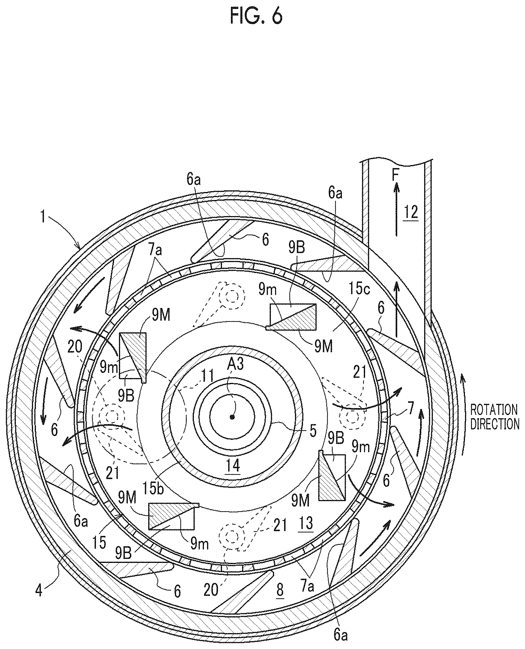
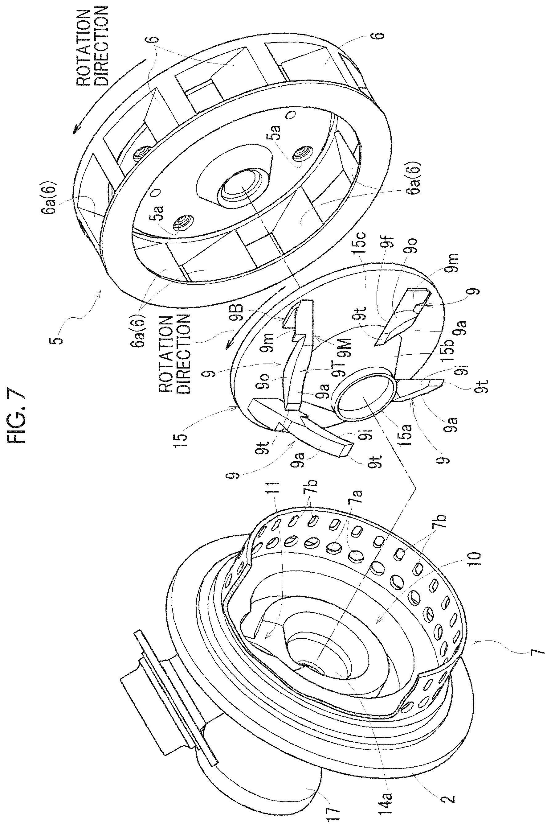
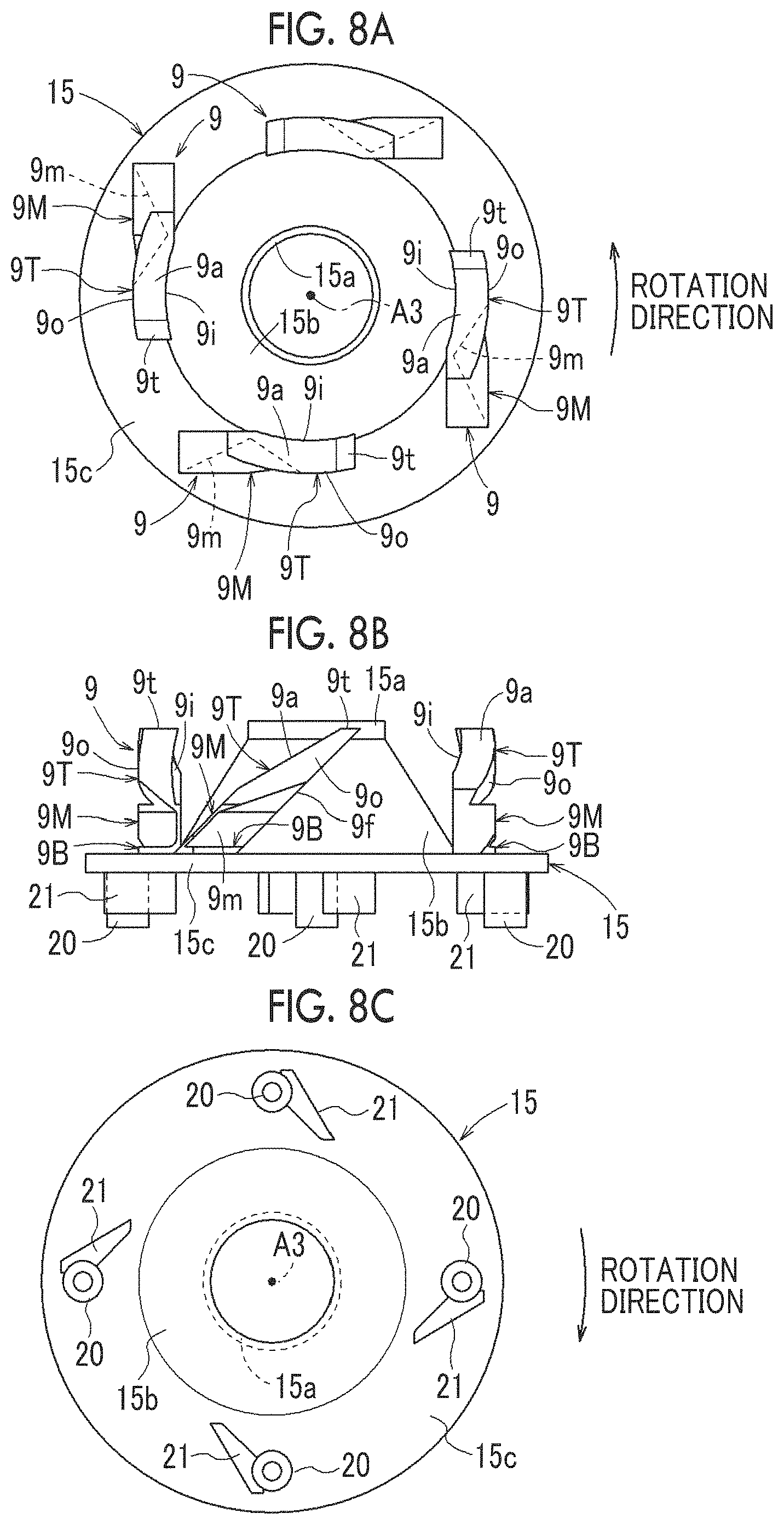
Slurry production apparatus
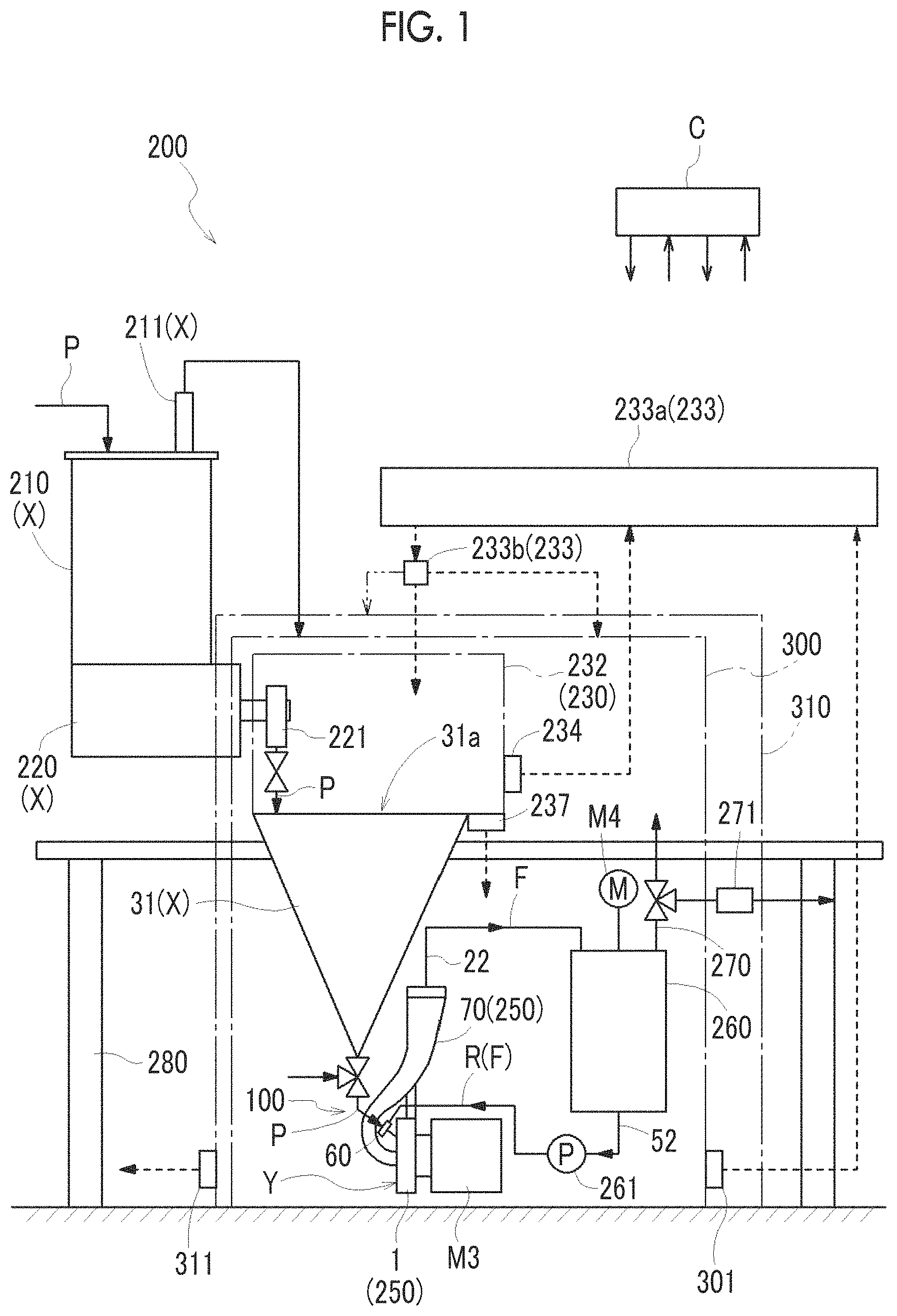
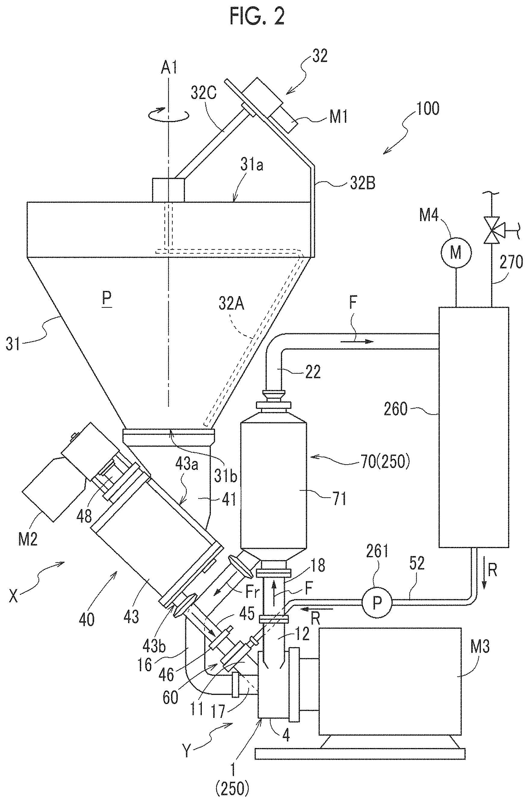
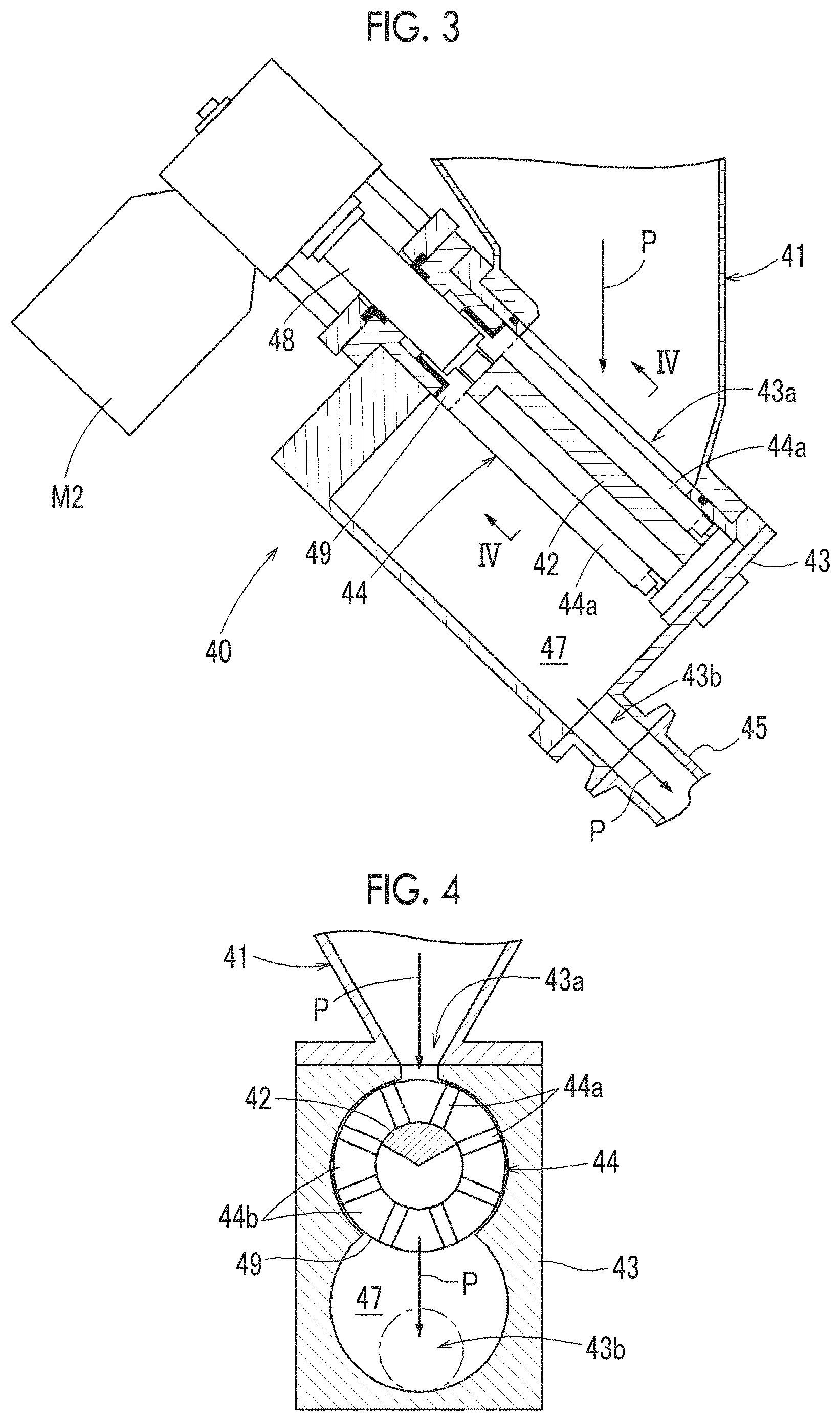
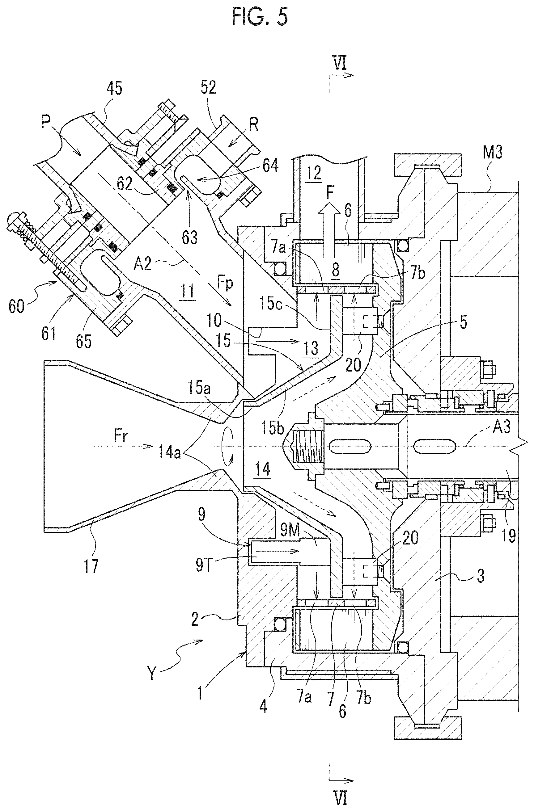
The content of Japanese Patent Application No. 2019-056461, on the basis of which priority benefits are claimed in an accompanying application data sheet, is in its entirety incorporated herein by reference. Certain embodiments of the present invention relate to a slurry production apparatus. Hitherto, a slurry production apparatus for producing a slurry by mixing a powder and a liquid has been used. The related art discloses a dispersion system that suctions and mixes a powder supplied to a hopper and liquid with a centrifugal dispersion mixing pump. Configuration 1 A slurry production apparatus includes: a mixing device that mixes a liquid and a powder to produce a slurry; a powder supply device that supplies the powder to the mixing device; a powder dry box that accommodates at least an opening portion of the powder supply device; and a first dry booth that accommodates the mixing device and the powder dry box. According to the above configuration, since the opening portion of the powder supply device is accommodated in the powder dry box, a situation where the powder comes into contact with moist air can be avoided, and deterioration of the quality of the slurry can be suppressed. Further, the mixing device and the powder dry box are accommodated in the first dry booth. Therefore, the opening portion of the powder supply device is accommodated in the powder dry box and further accommodated in the first dry booth, so that contact between the powder and moist air can be further suppressed. In addition to the opening portion of the powder supply device, the mixing device is also accommodated in the first dry booth. Therefore, even in a case where the powder is supplied from the powder supply device to the mixing device, contact between the powder and moist air can be suppressed. Therefore, introduction of the powder that absorbs moisture and deteriorates in quality into the mixing device can be suppressed, and as a result, deterioration of the quality of the slurry produced by the mixing device can be suppressed. Configuration 2 The slurry production apparatus may further include: a second dry booth that accommodates the first dry booth. According to the above configuration, since the first dry booth is accommodated in the second dry booth, the inside of the first dry booth can be further isolated from outside air. Accordingly, contact of the powder with moist air in the opening portion of the powder supply device accommodated in the first dry booth and the powder dry box can be further suppressed. Furthermore, even when the powder is supplied from the powder supply device to the mixing device, contact of the powder with moist air can be further suppressed. Therefore, deterioration of the quality of the slurry can be further suppressed. Configuration 3 In the slurry production apparatus, a first set dew point temperature of the first dry booth may be higher than a second set dew point temperature of the powder dry box. In the powder dry box, there is a possibility that the powder may come into contact with the air when the powder is fed into the powder supply device or when the powder is stirred. On the other hand, since the mixing device that mixes the liquid and the powder is in a closed space, the possibility that the powder may be directly exposed to the air is small in the first dry booth that accommodates the mixing device. Therefore, the dryness required for the first dry booth is lower than that of the powder dry box. As in the above configuration, since the first set dew point temperature of the first dry booth can be set to higher than the second set dew point temperature of the powder dry box, an increase in running cost can be suppressed. Furthermore, the dew point temperature can be lowered stepwise from the outside toward the first dry booth and the powder dry box. Therefore, it is easy to adjust the dew point temperature inside the powder dry box to be low, and the running cost can be reduced. Configuration 4 In the slurry production apparatus, an atmospheric pressure of the powder dry box may be higher than an atmospheric pressure of the first dry booth. According to the above configuration, since the atmospheric pressure of the powder dry box is higher than the atmospheric pressure of the first dry booth, the flow of the air of the first dry booth into the powder dry box can be suppressed. Accordingly, contact of the powder with the moist air in the opening portion of the powder supply device in the powder dry box can be further suppressed. Configuration 5 In the slurry production apparatus, the slurry may be a positive electrode active material slurry, a negative electrode active material slurry, or a solid electrolyte slurry used for manufacturing an all-solid-state battery. As described above, in the above slurry production apparatus, deterioration of quality due to contact of the powder used for producing the slurry with moist air can be suppressed. Therefore, by using the slurry production apparatus for producing a positive electrode active material slurry, a negative electrode active material slurry, or a solid electrolyte slurry as in the above configuration, deterioration of the quality of the slurry can be suppressed. Accordingly, deterioration of the quality of an all-solid-state battery can be suppressed. Configuration 6 In the slurry production apparatus, the powder may contain a sulfide solid electrolyte. As described above, in the above slurry production apparatus, in a case where a slurry is produced using a sulfide solid electrolyte that is a powder, contact of the powder with moist air can be suppressed. Therefore, in a case of using the sulfide solid electrolyte as the powder as in the above configuration, the generation of toxic hydrogen sulfide due to the contact of the sulfide solid electrolyte with moist air can be suppressed. Therefore, by producing a slurry in a state where the contact between the sulfide solid electrolyte and moist air is suppressed and manufacturing a battery, a decrease in battery performance such as a decrease in output characteristics and a reduction in service life can be suppressed. Furthermore, since generation of hydrogen sulfide can be suppressed, it is not necessary to provide a separate device such as a filter device for removing hydrogen sulfide, or the running cost can be reduced by reducing driving of the device. Configuration 7 In the slurry production apparatus, a filter may be provided in an exhaust portion of the first dry booth. According to the above configuration, discharge of odors, harmful gases, and the like to the outside of the first dry booth is suppressed by filtering the odors, harmful gases, and the like using the filter. Configuration 8 The slurry production apparatus may further include: a dehumidifying unit that sends air at a third dew point temperature into the powder dry box; and a control unit that adjusts a first flow rate of the air at the third dew point temperature sent from the dehumidifying unit into the powder dry box so as to adjust a dew point temperature of the powder dry box to a second set dew point temperature, in which, when the dew point temperature of the powder dry box reaches the second set dew point temperature or lower, the control unit performs at least one of an adjustment of a second flow rate of the air at the third dew point temperature sent from the dehumidifying unit into the first dry booth, and an adjustment of a third flow rate of air sent from the powder dry box into the first dry booth. According to the above configuration, the control unit adjusts the first flow rate of the air at the third dew point temperature sent from the dehumidifying unit into the powder dry box so as to adjust the powder dry box to the second set dew point temperature. Furthermore, when the dew point temperature of the powder dry box reaches the desired second set dew point temperature or lower, the control unit adjusts the second flow rate of the air at the third dew point temperature sent from the dehumidifying unit into the first dry booth. Accordingly, a portion of the air at the third dew point temperature that has been sent from the dehumidifying unit into the powder dry box is used for adjusting the dew point temperature of the first dry booth. Accordingly, the air at the third dew point temperature from the dehumidifying unit can be effectively utilized to cause the first dry booth to reach the first set dew point temperature. In addition, when the dew point temperature of the powder dry box reaches the desired second set dew point temperature or lower, the control unit adjusts the third flow rate of the air sent from the powder dry box into the first dry booth. Accordingly, while maintaining the inside of the powder dry box at the desired second set dew point temperature, the air in the powder dry box can be effectively utilized to cause the first dry booth to reach the desired first set dew point temperature. Among powders used as materials for a slurry, there are some powders that absorb moisture in the air and deteriorate or solidify. In a case of producing a slurry with an apparatus of the related art using such a powder, the following problems are incurred. In the apparatus of the related art, the upper inlet of the hopper is opened. Then, when the powder is fed into the hopper or when the powder stored in the hopper is stirred, the powder absorbs moisture in the surrounding air, and the quality of the slurry deteriorates. Therefore, it is considered that in order to prevent the powder from absorbing moisture, a device for each portion such as a device for a portion in which the powder is fed into the hopper and a device for a portion in which the powder is stirred is installed in a sealed container such as a glove box which is dehumidified and reduced in dew point temperature. The glove box is a box whose inside is blocked from the outside air, and a hand can be inserted into the inside via a glove sealed from the outside of the glove box. However, the space in the glove box is a limited space that allows a worker to work via the glove. Furthermore, the work range is narrow due to work via the glove, and the carry-in and discharge of articles into the glove box are limited by the size of a pass box (opening portion provided in the glove box). For this reason, it is difficult to dispose the entire dispersion apparatus including the device for each portion such as the device for the portion in which the powder is fed into the hopper, the device for the portion in which the powder is stirred, and the like in the glove box without deteriorating the dew point temperature. In addition, even in a case where the device for each portion is disposed in the glove box, size restrictions are imposed on the device for each portion and work is restricted. Furthermore, when the devices for the respective portions are disposed in the glove box, it is difficult to connect the devices for the portions to form the dispersion apparatus. Embodiments of the present invention have been made in view of the above-described problems, and it is desirable to provide a slurry production apparatus capable of suppressing a reduction in slurry quality. (1) Configuration of Slurry Production Apparatus (1-1) Overall Configuration As illustrated in (1-2) Schematic Configuration of Dispersion System The configuration of each part of the dispersion system 100 will be briefly described below, and the detailed configuration will be described in detail later. The dispersion system 100 is configured to include a powder supply device X, a dispersion mixing section Y, a mixing mechanism 60, a recirculation mechanism portion 70, a cooling device 250, a tank 260, and a pressure vent portion 270. The powder supply device X is configured to include a feeder hopper 210, a feeder 220, a hopper 31, and a quantitative supply section 40 ( The feeder hopper 210 is a hopper that temporarily stores a powder P dry-transported from upstream. The feeder hopper 210 has an air vent 211 connected to the powder dry box 230. The air vent 211 discharges the dry air inside the feeder hopper 210 into the first dry booth 300 when the internal pressure of the feeder hopper 210 increases with the feeding of the powder P from the upstream. The air vent 211 is provided with a check valve, and when the feeder hopper 210 is not under pressure, the feeder hopper 210 is preferably closed so that the powder P is not affected by moisture. A filter may be provided at the discharge port of the air vent 211, and the dry air inside the feeder hopper 210 may be discharged from the air vent 211 into the first dry booth 300 via the filter. Alternatively, a filter may be provided at the discharge port of the air vent 211 so that the dry air inside the feeder hopper 210 is not discharged into the first dry booth 300 but may be opened to the atmosphere. The feeder 220 discharges the powder P stored in the feeder hopper 210 from a powder discharge port 221 (an example of an opening portion) while measuring the powder P. The feeder 220 is, for example, a screw type feeder. The powder discharge port 221 is disposed inside the powder dry box 230. The powder P discharged from the powder discharge port 221 is fed into the hopper 31 from an upper opening portion 31 The hopper 31 is a member having an inverted conical shape which is decreased in diameter from the upper portion toward the lower portion, and causes the powder P received from the upper opening portion 31 The mixing mechanism 60 mixes a liquid R (or slurry F) supplied from the tank 260 with the powder P. The dispersion mixing section Y disperses and mixes the powder P and the liquid R mixed by the mixing mechanism 60. The recirculation mechanism portion 70 circulates and supplies the liquid R containing the powder P that has not been completely dissolved (hereinafter, undissolved slurry Fr), to the dispersion mixing section Y. The cooling device 250 is a device that cools the dispersion mixing section Y in order to suppress alteration of the slurry F due to a temperature rise. Specifically, the cooling device 250 is a cold water jacket through which supplied cold water flows, and is provided so as to cover a main body casing 1 of the dispersion mixing section Y and the recirculation mechanism portion 70. The dew point temperature in the first dry booth 300 is set to −40° C. (first set dew point temperature), and the cooling device 250 is accommodated in the first dry booth 300. Accordingly, the occurrence of condensation on the surface of the cooling device 250 can be suppressed, which is desirable. The tank 260 is configured to continuously supply the liquid R in the tank 260 to the dispersion mixing section Y at a set flow rate. Therefore, the tank 260 functions as a solvent supply source that supplies the liquid R to the dispersion mixing section Y. Furthermore, the slurry F is supplied to the tank 260 from the recirculation mechanism portion 70. Therefore, the tank 260 functions as a slurry recovery source for recovering the slurry F. The pressure vent portion 270 reduces the pressure in the tank 260 by exhausting gas from the tank 260. Specifically, the pressure vent portion 270 is a gas flow path, and connects the inside of the tank 260 to the powder dry box 230 via a valve. A gas flow path branched from the valve to exhaust the gas from the tank 260 to the outside is provided, and a filter 271 is disposed in the gas flow path. When the gas is exhausted from the tank 260 to the outside, the gas in the tank 260 is exhausted through the filter 271. Accordingly, malodor and scattering of substances are suppressed. In the dispersion system 100 of the slurry production apparatus 200, the slurry F is generally produced as follows. The powder P supplied from the powder supply device X and the liquid R (or slurry F) supplied from the tank 260 by a pump 261 are mixed by the mixing mechanism 60 and supplied to the dispersion mixing section Y. In the dispersion mixing section Y, the powder P and the liquid R are dispersed and mixed and sent to the recirculation mechanism portion 70. The recirculation mechanism portion 70 circulates and supplies the liquid R containing the powder P that has not been completely dissolved (hereinafter, undissolved slurry Fr) to the dispersion mixing section Y, and sends the slurry F to the tank 260. The slurry F inside the tank 260 is stirred by a tank stirring motor M4. (1-3) Dehumidifying Unit The dehumidifying unit 233 has a dehumidifying portion 233 For example, the dehumidifying portion 233 For example, the dehumidifying portion 233 The flow rate adjusting portion 233 In the present embodiment, it is assumed that the flow rate of the air having a dew point temperature of −80° C. (third dew point temperature) sent out by the dehumidifying portion 233 The air sent from the dehumidifying portion 233 In the above description, the dew point temperature of the air sent out by the dehumidifying portion 233 Similarly, in the above description, the dew point temperature in the powder dry box 230 is set to −80° C. and the dew point temperature in the first dry booth 300 is set to −40° C. However, the dew point temperatures are not particularly limited as long as the powder treated by the slurry production apparatus 200 can be prevented from coming into contact with moist air. For example, the dew point temperature in the powder dry box 230 may be −40° C. to −90° C. The dew point temperature in the first dry booth 300 may be −30° C. or lower. The dew point temperature in the first dry booth 300 may be any dew point temperature that does not cause condensation in the cooling device 250 installed in the first dry booth 300, and for example, may be −20° C. to −30° C. In the above description, the dehumidifying unit 233 dehumidifies the air in the powder dry box 230 and the first dry booth 300 but may also dehumidify the air in the second dry booth 310. (1-4) Powder Dry Box, First Dry Booth, and Second Dry Booth The powder dry box 230, the first dry booth 300, and the second dry booth 310 are partitions separated from the external space in order to maintain the atmosphere of the internal space in a predetermined state. In particular, the powder dry box 230 is a partition for maintaining only the atmosphere of a limited necessary portion in the slurry production apparatus 200 in a predetermined state. For example, these partitions are synthetic resin panels. However, the powder dry box 230, the first dry booth 300, and the second dry booth 310 may be used to block the powder P in the internal spaces from moisture and may be made of various materials such as a vinyl curtain, materials having heat insulation, or metal. Regarding the relationship between the powder dry box 230, the first dry booth 300, and the second dry booth 310 described above, the powder dry box 230 is accommodated in the first dry booth 300, and the first dry booth 300 is accommodated in the second dry booth 310. Hereinafter, each of the powder dry box 230, the first dry booth 300, and the second dry booth 310 will be described. The powder dry box 230 accommodates the powder discharge port 221 (the example of the opening portion) of the feeder 220 which is an opening portion of the powder supply device X, and the upper opening portion 31 As described above, the air having a dew point temperature of −80° C. (third dew point temperature) is sent into the powder dry box 230 from the dehumidifying portion 233 In particular, the powder P discharged from the powder discharge port 221 of the powder supply device X falls inside the powder dry box 230 and is fed into the hopper 31 from the upper opening portion 31 The powder dry box 230 is provided with the damper 234 that causes the powder dry box 230 to communicate with the dehumidifying portion 233 In the present embodiment, the dew point temperatures of the powder dry box 230 and the first dry booth 300 are adjusted according to the control of the control unit C, for example, as follows. First, by adjusting the opening degree of the flow rate adjusting portion 233 Next, when the dew point temperature in the powder dry box 230 reaches −80° C. (second set dew point temperature), the damper 234 is closed. Then, by adjusting the opening degree of the flow rate adjusting portion 233 By such control, the inside of the powder dry box 230 can be adjusted to −80° C. (second set dew point temperature), and the inside of the first dry booth 300 can be adjusted to −40° C. (first set dew point temperature). Here, in the present embodiment, as illustrated in In such an arrangement, the damper 237 is provided in a lower portion of the powder dry box 230 so as to open downward. Accordingly, when the damper 237 is opened, the air having a dew point temperature of −80° C. in the powder dry box 230 is sent from the powder dry box 230 so as to advance downward in the first dry booth 300. In addition, the first dry booth 300 accommodates the powder dry box 230 and the mixing device. For example, the mixing device includes the dispersion mixing section Y, the mixing mechanism 60, the recirculation mechanism portion 70, the cooling device 250, the tank 260, and the pressure vent portion 270. In the present embodiment, as illustrated in As described above, the air having a dew point temperature of −80° C. (third dew point temperature) is sent from the dehumidifying portion 233 In addition to the opening portion of the powder supply device X, the mixing device is also accommodated in the first dry booth 300. Therefore, even in a case where the powder is supplied from the powder supply device X to the mixing device, contact of the powder with moist air can be suppressed. Therefore, introduction of the powder that absorbs moisture and deteriorates in quality into the mixing device can be suppressed, and as a result, deterioration of the quality of the slurry produced by the mixing device can be suppressed. Furthermore, as described above, the set dew point temperature of the air in the first dry booth 300 is −40° C. (first set dew point temperature), and the set dew point temperature of the air in the powder dry box 230 is higher than −80° C. (second set dew point temperature). In this case, the dew point temperature can be managed more precisely by providing a plurality of dehumidifying units. The plurality of dehumidifying units include a dehumidifying unit for adjusting the dew point temperature of the first dry booth 300 and a dehumidifying unit for adjusting the dew point temperature of the powder dry box 230. In the powder dry box 230, there is a possibility that the powder may come into contact with the air when the powder is fed into the powder supply device X or when the powder is stirred. On the other hand, since the mixing device that mixes the liquid and the powder is in a closed space, the possibility that the powder may be directly exposed to the air is small in the first dry booth 300 that accommodates the mixing device. Therefore, the dryness required for the first dry booth 300 is lower than that of the powder dry box 230. As described above, since the set dew point temperature (−40° C.: first set dew point temperature) of the first dry booth 300 can be set to higher than the set dew point temperature (−80° C.: second set dew point temperature) of the powder dry box, an increase in running cost can be suppressed. Furthermore, the dew point temperature can be lowered stepwise from the outside toward the first dry booth 300 and the powder dry box 230. Therefore, it is easy to adjust the dew point temperature inside the powder dry box 230 to be low, and the running cost can be reduced. Although the air exhausted from the first dry booth 300 returns to the dehumidifying unit 233, it is preferable that the filter 301 is provided in an exhaust portion of the first dry booth 300. The filter 301 is preferably formed of a material capable of filtering odors, harmful gases, and the like. Accordingly, introduction of odors, harmful gases, and the like into the dehumidifying unit 233 and further into the powder dry box 230 and the first dry booth 300 is suppressed, and contamination of the air therein can be suppressed. The second dry booth 310 accommodates the first dry booth 300. Since the first dry booth 300 is accommodated in the second dry booth 310, the inside of the first dry booth 300 can be further isolated from outside air. Accordingly, contact of the powder with moist air in the opening portions of the powder supply device X accommodated in the first dry booth 300 and the powder dry box 230 can be further suppressed. Furthermore, even when the powder is supplied from the powder supply device X to the mixing device, contact of the powder with moist air can be further suppressed. Therefore, deterioration of the quality of the slurry can be further suppressed. In the present embodiment, as illustrated in By the control of the control unit C, the atmospheric pressure in the powder dry box 230 is adjusted to a positive pressure higher than the atmospheric pressure outside the second dry booth 310 (hereinafter referred to as “outside air pressure”). The atmospheric pressure of the powder dry box 230 is, for example, higher than the outside air pressure by about 5 Pa. Accordingly, the flow of outside air into the powder dry box 230 can be suppressed. Therefore, the dew point temperature in the powder dry box 230 can be kept low, and contact of the powder with the moist air in the opening portions of the powder supply device X can be further suppressed. In addition, by the control of the control unit C, the atmospheric pressure of the first dry booth 300 is adjusted to a positive pressure higher than the outside air pressure. The atmospheric pressure of the first dry booth 300 is higher than the outside air pressure, for example, by about 2 to 3 Pa. Accordingly, the flow of outside air into the first dry booth 300 can be suppressed. Therefore, contact of the powder with the moist air in the opening portions of the powder supply device X in the powder dry box 230 accommodated in the first dry booth 300 can be further suppressed. Furthermore, even when the powder is supplied from the powder supply device X to the mixing device, contact of the powder with moist air can be further suppressed. Although described above, the dehumidifying unit 233 may dehumidify the air in the second dry booth 310 as indicated by a two-dot chain line in As described above, the atmospheric pressure of the powder dry box 230 (higher than the outside air pressure by about 5 Pa) is higher than the atmospheric pressure of the first dry booth 300 (higher than the outside air pressure by about 2 to 3 Pa). Therefore, the flow of the air of the first dry booth 300 into the powder dry box 230 can be suppressed. Accordingly, contact of the powder with the moist air in the opening portions of the powder supply device X in the powder dry box 230 can be further suppressed. Moreover, by the control of the control unit C, the atmospheric pressure of the second dry booth 310 is adjusted to a negative pressure lower than the outside air pressure (lower than the outside air pressure by about 2 to 3 Pa). Therefore, the outflow of the air in the second dry booth 310 can be suppressed. Accordingly, the outflow of the air in the space of any of the powder dry box 230, the first dry booth 300, and the second dry booth 310 is suppressed, and the outflow of, for example, odors and harmful gases in these spaces can be suppressed. Since the atmospheric pressures in the powder dry box 230 and the first dry booth 300 are more positive than the outside air pressure, there are cases where the air in the powder dry box 230 and the first dry booth 300 flows to the second dry booth 310. By causing the atmospheric pressure in the second dry booth 310 to be a negative pressure lower than the outside air pressure, while suppressing the flow of the air from the outside into the powder dry box 230 and the first dry booth 300, and the outflow of odors, harmful gases, and the like in the powder dry box 230, the first dry booth 300, and the second dry booth 310 can be suppressed. Here, in a case where the dew point temperature of the powder dry box 230 is maintained at −80° C. or lower and the dew point temperature of the first dry booth 300 is maintained at −40° C. or lower, the air flow is as follows, for example. First, air flows in a circulation of a flow from the dehumidifying unit 233 through the powder dry box 230 and the first dry booth 300 to the dehumidifying unit 233. Second, air flows in a circulation of a flow from the dehumidifying unit 233 through the first dry booth 300 to the dehumidifying unit 233. By configuring the air flow in this way, the dehumidifying unit 233 can be shared by the powder dry box 230 and the first dry booth 300, and there is no need to separately provide the dehumidifying unit for the first dry booth 300 and the dehumidifying unit 233, thereby suppressing an increase in cost. (1-5) Control Unit The control unit C is a calculation processing device including a CPU, a storage unit, and the like, and controls the overall operation of the slurry production apparatus 200. In particular, the control unit C adjusts the flow rate of the air from the dehumidifying unit 233 to the powder dry box 230 and the first dry booth 300, and adjusts the flow rate of the air from the powder dry box 230 to the first dry booth 300. First, the control unit C adjusts the first flow rate Q1 of the air at −80° C. (third dew point temperature) sent from the dehumidifying portion 233 In addition, the control unit C opens the damper 234 of the powder dry box 230 so as to cause the air sent into the powder dry box 230 to return to the dehumidifying portion 233 Next, when the dew point temperature of the powder dry box 230 reaches −80° C. (second set dew point temperature) or lower, the control unit C closes the damper 234 and performs the following adjustment. The control unit C controls the flow rate adjusting portion 233 Furthermore, the control unit C controls the damper 237 to perform a second adjustment of the third flow rate Q3 of the air so as to send the air in the powder dry box 230 into the first dry booth 300. As described above, when the dew point temperature of the powder dry box 230 reaches −80° C. (second set dew point temperature) or lower, the control unit C closes the damper 234 to send the air having a dew point temperature of −80° C. (third dew point temperature) from the dehumidifying portion 233 By the first adjustment described above, the second flow rate Q2, which is a portion of the air at −80° C. (third dew point temperature) that has been sent from the dehumidifying portion 233 In addition, by the second adjustment described above, while maintaining the inside of the powder dry box 230 at the desired −80° C. (second set dew point temperature), the air in the powder dry box 230 can be effectively utilized to cause the first dry booth 300 to reach the desired −40° C. (first set dew point temperature). Further, by performing both the first adjustment and the second adjustment by the control unit C, the air at −80° C. (third dew point temperature) from the dehumidifying portion 233 In the above description, when the dew point temperature of the powder dry box 230 reaches −80° C. (second set dew point temperature) or lower, the control unit C performs both the first adjustment and the second adjustment described above, but may also perform only one of the first adjustment and the second adjustment when the dew point temperature of the powder dry box 230 reaches −80° C. (second set dew point temperature) or lower. This will be described below. In a case where the dew point temperature of the powder dry box 230 reaches −80° C. (second set dew point temperature) or lower and only the first adjustment is performed, the following control is performed, for example. When the dew point temperature of the powder dry box 230 reaches −80° C. (second set dew point temperature) or lower, the control unit C closes the damper 234. The control unit C closes the damper 237 so as not to send the air in the powder dry box 230 into the first dry booth 300. Such control is preferably performed after the powder P is fed into the hopper 31 from the powder discharge port 221 and the powder P is supplied to the dispersion system 100. Furthermore, the control unit C performs control to adjust the opening degree of the flow rate adjusting portion 233 On the other hand, in a case where the dew point temperature of the powder dry box 230 reaches −80° C. (second set dew point temperature) or lower and only the second adjustment is performed, the following control is performed, for example. When the dew point temperature of the powder dry box 230 reaches −80° C. (second set dew point temperature) or lower, the control unit C closes the damper 234. The control unit C adjust the opening degree of the flow rate adjusting portion 233 Furthermore, the control unit C controls the damper 237 to adjust the third flow rate Q3 of the air sent from the powder dry box 230 into the first dry booth 300. Accordingly, the inside of the powder dry box 230 is adjusted to −80° C. (second set dew point temperature), and the inside of the first dry booth 300 is adjusted to −40° C. (first set dew point temperature). When the dew point temperature of the powder dry box 230 becomes higher than −80° C. (second set dew point temperature), the control unit C may perform control again to circulate the air between the dehumidifying portion 233 In the above description, when the dew point temperature in the powder dry box 230 reaches −80° C. (second set dew point temperature), the damper 234 is closed, but the opening degree of the damper 234 may be adjusted. As described above, the control unit C control the atmospheric pressures in the powder dry box 230, the first dry booth 300, and the second dry booth 310 by controlling the dehumidifying unit 233. The control unit C controls the atmospheric pressure in the powder dry box 230 to, for example, a positive pressure higher than the outside air pressure by about 5 Pa. Similarly, the control unit C controls the atmospheric pressure of the first dry booth 300 to a positive pressure higher than the outside air pressure by about 2 to 3 Pa, and controls the atmospheric pressure of the second dry booth 310 to a negative pressure lower than the outside air pressure by about 2 to 3 Pa. (2) Slurry Produced by Slurry Production Apparatus In the slurry production apparatus 200, it is possible to produce the slurry F using various kinds of powder P and liquid R. In particular, the slurry production apparatus 200 can be suitably used for producing a slurry for manufacturing a positive electrode, a negative electrode, or a solid electrolyte of an all-solid-state battery, that is, a positive electrode active material slurry, a negative electrode active material slurry, or a solid electrolyte slurry. In the slurry production apparatus 200, deterioration of quality due to contact of the powder used for producing the slurry with moist air can be suppressed. Therefore, by using the slurry production apparatus 200 for producing a positive electrode active material slurry, a negative electrode active material slurry, or a solid electrolyte slurry, deterioration of the quality of the slurry can be suppressed. Accordingly, deterioration of the quality of an all-solid-state battery can be suppressed. The positive electrode active material slurry is produced by dispersing a positive electrode active material, a conductivity aid, a binder, and the like in a solvent. The negative electrode active material slurry is produced by dispersing a negative electrode active material, a conductivity aid, a binder, and the like in a solvent. The solid electrolyte slurry is produced by dispersing a solid electrolyte, a conductivity aid, a binder, and the like in a solvent. The positive electrode active material slurry may contain a solid electrolyte. The negative electrode active material slurry may contain a solid electrolyte. The positive electrode active material is exemplified by an olivine type positive electrode active material. The olivine type positive electrode active material is a material having an olivine type structure, and is not particularly limited as long as it is a positive electrode active material that can be used for a lithium-ion battery. Examples of the olivine type positive electrode active material include active materials represented by a chemical formula LixMyPOz(M=Fe, Mn, Co, and Ni, 0.5≤x≤1.5, 0.5≤y≤1.5, 2≤z≤7). Particularly, LiFePO4, which is an olivine type positive electrode active material having high material stability and a large theoretical capacity, is preferable. Moreover, application to a positive electrode material highly containing nickel alkalized by moisture in the air is also possible. The negative electrode active material is not particularly limited as long as lithium ions and the like can be occluded and released. Specific examples of the negative electrode active material may include metals such as Li, Sn, Si, or In, alloys of Li and Ti, Mg, or Al, or carbon materials such as hard carbon, soft carbon, or graphite, and combinations of these. In particular, from the viewpoint of cycle characteristics and discharge characteristics, lithium titanate (LTO, Li4Ti5O12) and a lithium-containing alloy are preferable. As the solid electrolyte, a sulfide solid electrolyte used as a solid electrolyte of an all-solid-state battery can be used. Examples thereof include Li2S—SiS2, LiX—Li2S—SiS2, LiX—Li2S—P2S5, LiX—Li2S—P2S5, LiX—Li2S—Li2O—P2S5, Li2S—P2S5, Li3PS4—LiI—LiBr, and the like. Here, “X” represents I and/or Br. In the slurry production apparatus 200 described above, in a case where a slurry is produced using a sulfide solid electrolyte that is a powder, contact of the powder with moist air can be suppressed. Therefore, in a case of using the sulfide solid electrolyte as the powder, the generation of toxic hydrogen sulfide due to the contact of the sulfide solid electrolyte with moist air can be suppressed. Therefore, by producing a slurry in a state where the contact between the sulfide solid electrolyte and moist air is suppressed and manufacturing a battery, a decrease in battery performance such as a decrease in output characteristics and a reduction in service life can be suppressed. Furthermore, since generation of hydrogen sulfide can be suppressed, it is not necessary to provide a separate device such as a filter device for removing hydrogen sulfide, or the running cost can be reduced by reducing driving of the device. The conductivity aid is exemplified by, as well as carbon materials such as vapor grown carbon fiber (VGCF), acetylene black, ketjen black, carbon nanotube (CNT), or carbon nanofiber (CNF), metals such as nickel, aluminum, or stainless steel, and combinations thereof. The binder is exemplified by polymer resins such as polyvinylidene fluoride (PVDF), polytetrafluoroethylene (PTFE), polyimide (PI), polyamide (PA), polyamide-imide (PAI), butadiene rubber (BR), styrene butadiene rubber (SBR), nitrile-butadiene rubber (NBR), styrene-ethylene-butylene-styrene block copolymer (SEBS), or carboxymethylcellulose (CMC), and combinations thereof. The solvent is exemplified by butyl butyrate and dehydrated heptane. (3) Detailed Configuration of Slurry Production Apparatus Hereinafter, a part of the configuration of the dispersion system 100 and the control unit C in the configuration of the slurry production apparatus 200 will be described in more detail. Powder Supply Device As illustrated in The hopper 31 is formed in an inverted conical shape that is decreased in diameter from the upper portion toward the lower portion ad is disposed in a posture with a center axis A1 directed along a vertical direction. The transverse sectional shape of each of the upper opening portion 31 The stirring mechanism 32 is configured to include: a stirring blade 32A that is disposed in the hopper 31 and stirs the powder P in the hopper 31; a blade drive motor M1 that rotates the stirring blade 32A around the center axis A1 of the hopper 31; an attachment member 32B that supports the blade drive motor M1 to be positioned above the upper opening portion 31 The stirring blade 32A is configured by bending a rod-shaped member into a substantially V-shape, and is disposed so that in a state where one side portion is directed along the inner wall surface of the hopper 31, an end portion of the other side portion is pivotally supported so as to rotate coaxially with the center axis A1 of the hopper 31. Furthermore, the stirring blade 32A has a transverse sectional shape formed in a triangular shape, and is disposed so that a surface forming one side of the triangle is substantially parallel to the inner wall surface of the hopper 31. Accordingly, the stirring blade 32A is disposed so as to rotate around the center axis A1 along the inner wall surface of the hopper 31. As illustrated in Specifically, the quantitative supply section 40 is configured to include: an introduction portion 41 connected to the lower opening portion 31 The introduction portion 41 is formed in a tubular shape that causes the lower opening portion 31 Although an example in which the casing 43 is formed in a substantially rectangular parallelepiped shape and is connected to the hopper 31 via the introduction portion 41 in a posture inclined at 45 degrees with respect to the horizontal direction (left-right direction in As illustrated in The metering rotator 44 is configured by attaching a plurality of (for example, eight) plate-shaped partition walls 44 With the rotation of the metering rotator 44, each powder accommodation chamber 44 Therefore, in the powder supply device X, the powder P stored in the hopper 31 is supplied to the quantitative supply section 40 while being stirred by the stirring blade 32A, and the powder P is quantitatively supplied by the quantitative supply section 40 from the discharge port 43 More specifically, the pressure in the expansion chamber 47 in the casing 43 is in a negative pressure state (for example, about −0.06 MPa) due to the negative pressure suction force from the dispersion mixing section Y connected to the downstream side of the discharge port 43 In this state, as the powder P in the vicinity of the inner wall surface of the hopper 31 and the lower opening portion 31 In the above description, the powder P in the hopper 31 is supplied to the dispersion mixing section Y via the quantitative supply section 40. However, in a case of a powder P having adhesiveness, the quantitative supply section 40 is not used, and for example, the powder P may be directly supplied to the dispersion mixing section Y via the hopper 31 from the feeder 220 by controlling the rotation thereof. Alternatively, a passage that directly connects the hopper 31 and the dispersion mixing section Y is separately formed to be switchable between the supply of the powder P from the hopper 31 to the dispersion mixing section Y via the quantitative supply section 40 and the supply of the powder P from the hopper 31 to the dispersion mixing section Y, depending on the properties of the powder P. As illustrated in Tank and Mixing Mechanism As illustrated in The tank 260 is provided with: a solvent supply pipe 52 that connects the tank 260 to the mixing mechanism 60 and allows the liquid R to pass therethrough; a pump 261 that is provided in the solvent supply pipe 52 and delivers the liquid R from the tank 260 to the mixing mechanism 60 via the solvent supply pipe 52; and a flow rate adjusting valve (not illustrated) that adjusts the flow rate of the liquid R delivered from the tank 260 to the solvent supply pipe 52 to a set flow rate. The mixing mechanism 60 mixes the liquid R adjusted to the set flow rate with the powder P quantitatively supplied from the quantitative supply section 40 and supplies the mixture to the feed port 11. As illustrated in The mixing member 61 is configured to include: a tubular portion 62 that is configured to have a smaller diameter than the cylindrical feed port 11 and is disposed in a state of being inserted into the feed port 11 so as to form an annular slit 63 with the feed port 11; and an annular flow path forming portion 65 that forms an annular flow path 64 in the outer peripheral portion of the feed port 11 in a state of communicating with the annular slit 63 over the entire circumference. The powder discharge pipe 45 is connected to the mixing member 61 in a state of communicating with the tubular portion 62, and the solvent supply pipe 52 is connected to the mixing member 61 to supply the liquid R to the annular flow path 64 in a tangential direction. The powder discharge pipe 45, the tubular portion 62 of the mixing member 61, and the feed port 11 are arranged to be inclined such that an axial center A2 thereof is in an inclined posture in which the supply direction is downward (the angle with respect to the horizontal plane (left-right direction in That is, the powder P discharged from the discharge port 43 Dispersion Mixing Section The dispersion mixing section Y will be further described with reference to As illustrated in As illustrated also in The cylindrical stator 7 is provided with a plurality of through-holes 7 As illustrated in As illustrated in As illustrated in As illustrated in As illustrated in The supply chamber 13 and the introduction chamber 14 are configured to communicate with the blade chamber 8 via the plurality of through-holes 7 Specifically, the supply chamber 13 and the blade chamber 8 communicate with each other through a plurality of the supply chamber side through-holes 7 Each portion of the dispersion mixing section Y will be further described. As illustrated in The rotor 5 is connected to a drive shaft 19 of the pump drive motor M3 that passes through the rear wall portion 3 and is inserted into the main body casing 1, in a state of being concentric with the main body casing 1 in the main body casing 1, and is driven by the pump drive motor M3 to rotate. The rotor 5 is configured to generate so-called local boiling (cavitation) on a surface (back surface) 6 As illustrated in As illustrated in As illustrated in As illustrated in As illustrated in As illustrated in As illustrated in The scraping blade 9 will be further described with reference to The scraping blade 9 is configured in a rod shape provided with the base end part 9B fixed to the partition plate 15, an intermediate portion 9M in a state of being exposed to the supply chamber 13, and the tip part 9T in a state of being fitted in (that is, entering) the annular groove 10 in series in a direction from the base to the tip. As illustrated in As illustrated in That is, by providing the rod-shaped scraping blade 9 in the inclined posture as described above, the intermediate portion 9M exposed to the supply chamber 13 of the scraping blade 9 is located closer to the radially outer side of the rotor 5 than the tip part 9T fitted into the annular groove 10, and the radiating surface 9 As illustrated in In addition, among the four side surfaces of the tip part 9T having the quadrangular prim shape, a scraping surface 9 Accordingly, the preliminary mixture Fp scraped from the annular groove 10 by the tip part 9T of the scraping blade 9 is directed radially outward of the rotor 5 by the scraping surface 9 Furthermore, a tip surface 9 When the rotor 5 is driven to rotate in a direction in which the tip of the scraping blade 9 is directed forward when viewed in the axial center direction (viewed in the direction into the paper in The four scraping blades 9 configured in the above-described shape are respectively provided with the base end parts 9B fixed to the annular flat plate portion 15 As illustrated in Then, the introduction chamber 14 having a tapered shape that decreases in diameter toward the front wall portion 2 side of the main body casing 1 is formed between the swelling front surface of the rotor 5 and the rear surface of the partition plate 15, and the introduction port 17 is configured to communicate with the introduction chamber 14 via the tubular sliding contact portion 15 The annular supply chamber 13 communicating with the feed port 11 is formed between the front wall portion 2 of the main body casing 1 and the front surface of the partition plate 15. When the rotor 5 is driven to rotate, the partition plate 15 rotates integrally with the rotor 5 in a state where the tubular sliding contact portion 15 Recirculation Mechanism Portion The recirculation mechanism portion (an example of a separation portion) 70 is configured to separate the dissolved liquid in the cylindrical container 71 by specific gravity, and as illustrated in Here, although not illustrated, the recirculation mechanism portion 70 is configured such that an introduction pipe to which the discharge path 18 is connected is disposed so as to protrude toward the inside from the bottom surface of the cylindrical container 71, a discharge portion connected to the discharge path 22 is provided in the upper portion of the cylindrical container 71, a circulation portion connected to the circulation path 16 is provided in the lower portion, and a twisted plate that turns the flow of the slurry F discharged from the introduction pipe is disposed at the discharge upper end of the introduction pipe. Accordingly, bubbles of the liquid R can be separated from the slurry F, and the undissolved slurry Fr circulated and supplied to the circulation path 16 can be supplied into the introduction chamber 14 in a state where the bubbles of the liquid R are separated. Control Unit The control unit C controls the overall operation of the slurry production apparatus 200, and controls, for example, the rotating speed of the rotor 5 (the rotor blades 6). Specifically, the control unit C sets the rotating speed of the rotor blades 6 so that the pressure of the outlet region of the supply chamber side through-holes 7 In addition, as described above, the control unit C also controls the dew point temperatures of the powder dry box 230 and the first dry booth 300 and the atmospheric pressures of the powder dry box 230, the first dry booth 300, and the second dry booth 310. Operation of Slurry Production Apparatus Next, the operation of the slurry production apparatus 200 will be described. First, the powder dry box 230, the first dry booth 300, and the second dry booth 310 are operated to lower the dew point temperatures. In addition, the cooling device 250 is operated. By adjusting the dehumidifying unit 233, the atmospheric pressure of the powder dry box 230 is set to a positive pressure (a state higher than the outside air pressure by about 5 Pa), the atmospheric pressure of the first dry booth 300 is set to a positive pressure (a state higher than the outside air pressure by about 2 to 3 Pa) and the atmospheric pressure of the second dry booth 310 is set to a negative pressure (a state lower than the outside air pressure by about 2 to 3 Pa). Next, the rotor 5 is rotated in a state where suction of the powder P via the powder discharge pipe 45 is stopped by closing the shutter valve 46, and thereafter only the liquid R of the tank 260 is supplied by operating the pump 261 to start the operation of the dispersion mixing section Y. By supplying the liquid R to the dispersion mixing section Y after rotating the rotor 5, a mechanical seal on the back surface of the rotor 5 is brought into close contact with the rotor 5, and liquid leakage from the back surface of the rotor 5 can be prevented. Due to the negative pressure suction force of the dispersion mixing section Y, the liquid R is quantitatively supplied to the mixing member 61 of the mixing mechanism 60 continuously in a predetermined amount. When a predetermined operation time has elapsed and the inside of the dispersion mixing section Y is in a negative pressure state (for example, a vacuum state of about −0.06 MPa), the shutter valve 46 is opened. Accordingly, the expansion chamber 47 of the powder supply device X is brought into a negative pressure state (about −0.06 MPa), and the inside of the introduction portion 41 and the vicinity of the lower opening portion 31 Then, the powder P is supplied from the feeder 220 to the hopper 31 by operating the powder supply device X. The powder P stored in the hopper 31 is quantitatively supplied to the mixing member 61 of the mixing mechanism 60 continuously in a predetermined amount via the expansion chamber 47 of the quantitative supply section 40 from the lower opening portion 31 In this case, depending on the properties of the powder, the quantitative supply section 40 is not used, and a predetermined amount of the powder may be supplied directly from the feeder 220 to the mixing mechanism 60 via the hopper 31. In this case, the powder is supplied to the mixing mechanism. 60 by controlling the supply speed of the feeder 220 so as not to exceed the powder processing capability of the mixing mechanism 60. The powder P is supplied from the mixing member 61 of the mixing mechanism 60 to the feed port 11 through the tubular portion 62 of the mixing member 61, and the liquid R is supplied to the feed port 11 through the annular slit 63 in the form of a hollow cylindrical vortex without a break, the powder P and the liquid R are premixed by the feed port 11, and the preliminary mixture Fp is introduced into the annular groove 10. When the supply of the predetermined amount of the powder P is completed, the powder discharge port 221 and the shutter valve 46 are closed to stop the suction of the powder P via the powder discharge pipe 45 such that the supply of the powder to the dispersion mixing section Y from the powder supply device X is stopped. When the rotor 5 is driven to rotate and the partition plate 15 rotates integrally with the rotor 5, the scraping blades 9 provided concentrically on the partition plate 15 revolve in a state where the tip parts 9T are fitted in the annular groove 10. Then, as indicated by solid line arrows in The preliminary mixture Fp introduced into the annular groove 10 undergoes a shearing action when scraped by the tip parts 9T of the scraping blades 9. In this case, a shearing action acts between the outward side surface 90 of the tip part 9T of the scraping blade 9 and the inward inner surface of the annular groove 10 on the inner side, and between the inward side surface 9 That is, since the shearing force can be applied to the preliminary mixture Fp in the supply chamber 13, the preliminary mixture Fp to be scraped out is mixed by receiving the shearing action from the scraping blades 9 and the supply chamber side through-holes 7 The slurry F discharged from the discharge portion 12 is supplied to the recirculation mechanism portion 70 through the discharge path 18, and in the recirculation mechanism portion 70, the undissolved slurry Fr in a state of containing the powder P that is not completely dissolved and the slurry F in a state where the powder P is almost completely dissolved are separated from each other, and the bubbles of the liquid R are separated. The undissolved slurry Fr is supplied again to the introduction port 17 of the dispersion mixing section Y through the circulation path 16, and the slurry F is supplied to the tank 260 through the discharge path 22. The undissolved slurry Fr is introduced into the introduction chamber 14 via the throttle portion 14 Here, the rotating speed of the rotor blades 6 is set by the control unit so that the pressure in the blade chamber 8 which is the outlet region of the supply chamber side through-holes 7 Accordingly, by setting the rotating speed of the rotor blades 6, the pressure in the blade chamber 8 which is the outlet region becomes equal to or lower than the saturation vapor pressure of the liquid R (3.169 kPa in the case of water at 25° C.) over the entire circumference. Therefore, at least in the region in the blade chamber 8 immediately after passing through the supply chamber side through-holes 7 Crushing of the aggregates of the powder P is promoted by the expansion and contraction of the bubbles due to the cavitation generated here. As a result, a high-quality slurry F in which the powder P is favorably dispersed in the liquid R can be generated over almost the entire slurry F present on the entire circumference in the blade chamber 8. (1) In the above-described embodiment, the powder supply device X is configured to include the feeder hopper 210, the feeder 220, the hopper 31, and the like. As another form of the powder supply device X, a form in which the powder P is suctioned with a hose or the like from a bag containing the powder P is also possible. In this form, the opening portion of the powder supply device X is the opening of the bag and the suction port of the hose, and these opening portions are accommodated in the powder dry box 230. (2) In the above-described embodiment, the powder dry box 230 accommodates the powder discharge port 221 (an example of the opening portion) of the feeder 220 that is the opening portion of the powder supply device X, and the upper opening portion 31 (3) In the above-described embodiment, the dispersion system 100 is formed by the powder supply device X, the dispersion mixing section Y, the mixing mechanism 60, the recirculation mechanism portion 70, the cooling device 250, the tank 260, and the pressure vent portion 270. In addition, the mixing device is exemplified by the dispersion mixing section Y, the mixing mechanism 60, the recirculation mechanism portion 70, the cooling device 250, the tank 260, and the pressure vent portion 270. The first dry booth 300 accommodates the mixing device, and the mixing device may include at least one of the dispersion mixing section Y, the mixing mechanism 60, the recirculation mechanism portion 70, the cooling device 250, the tank 260, and the pressure vent portion 270. More specifically, the mixing device may just include at least the mixing mechanism 60 among the devices. That is, the mixing mechanism 60, which is an example of the mixing device, mixes the liquid R adjusted to the set flow rate with the powder P that is quantitatively supplied from the powder supply device X and the first dry booth 300 may accommodate at least the mixing mechanism 60. (4) In the above-described embodiment, the dehumidifying unit 233 includes the flow rate adjusting portion 233 However, although the dehumidifying unit 233 including the dehumidifying portion 233 In this case, the control unit C adjusts the first flow rate Q1 of the air at −80° C. (third dew point temperature) sent from the dehumidifying portion 233 When the dew point temperature of the powder dry box 230 reaches −80° C. (second set dew point temperature) or lower, the control unit C closes the damper 234 and controls the flow rate adjusting portion 233 Unlike the above, the flow rate adjusting portion 233 In this case, the control unit C adjusts the first flow rate Q1 of the air at −80° C. (third dew point temperature) sent from the dehumidifying portion 233 When the dew point temperature of the powder dry box 230 reaches −80° C. (second set dew point temperature) or lower, the damper 237 is controlled to perform the second adjustment of the third flow rate Q3 of the air sent into the first dry booth 300 from the powder dry box 230 for the air in the powder dry box 230. (5) In addition to the configuration of the above-described embodiment, a configuration that monitors the amount of the powder P fed into the hopper 31 may be added. For example, a sensor A capable of detecting the powder P is provided in the lower portion of the hopper 31 at a predetermined position from the lowermost end. The sensor A can detect that the powder P has been fed into the hopper 31 from the lowermost end of the hopper 31 to the predetermined position. In a case where the sensor A detects the powder P, a control unit (not illustrated) slows down the supply speed of the powder P from the feeder 220 to the hopper 31. Accordingly, excessive supply of the powder P to the hopper 31 can be suppressed, and clogging of the powder P in the hopper 31 can be suppressed. Furthermore, a sensor B that detects accumulation of the powder P in substantially the entire hopper 31 may be provided in the vicinity of the uppermost end of the hopper 31. In a case where the sensor B detects the powder P, a control unit (not illustrated) stops the supply of the powder P from the feeder 220 to the hopper 31. Accordingly, an overflow of the powder P from the hopper 31 can be suppressed. (6) In the above-described embodiment, an example in which the dispersion system 100 is formed by the powder supply mechanism X, the dispersion mixing section Y, the mixing mechanism 60, the recirculation mechanism portion 70, the cooling device 250, the tank 260, and the like is described. However, a mixer in which a powder is fed from the upper portion of a tank and dispersed by a self-rotating stirring blade or a biaxial kneader may be used. The configurations disclosed in the above-described embodiments (including other embodiments, the same applies hereinafter) can be applied in combination with the configurations disclosed in the other embodiments as long as no contradiction arises. In addition, the embodiments disclosed in this specification are merely examples, and the embodiments of the present invention are not limited thereto and can be appropriately modified without departing from the scope of the embodiments of the present invention. It should be understood that the invention is not limited to the above-described embodiment, but may be modified into various forms on the basis of the spirit of the invention. Additionally, the modifications are included in the scope of the invention. A slurry production apparatus includes: a mixing device (including a dispersion mixing section) that mixes a liquid and a powder to produce a slurry; a powder supply device that supplies the powder to the mixing device; a powder dry box that accommodates an opening portion of the powder supply device; and a first dry booth that accommodates the mixing device and the powder dry box. 1. A slurry production apparatus comprising:
a mixing device configured to mix a liquid and a powder to produce a slurry; a powder supply device configured to supply the powder to the mixing device; a powder dry box configured to accommodate at least an opening portion of the powder supply device; and a first dry booth configured to accommodate, within the first dry booth, the mixing device and the powder dry box, wherein:
the powder supply device comprises a hopper, and the powder dry box surrounds an opening portion of the hopper so that the opening portion of the hopper is not open to the atmosphere. 2. The slurry production apparatus according to a second dry booth configured to accommodate the first dry booth. 3. The slurry production apparatus according to wherein a first set dew point temperature of the first dry booth is higher than a second set dew point temperature of the powder dry box. 4. The slurry production apparatus according to wherein an atmospheric pressure of the powder dry box is higher than an atmospheric pressure of the first dry booth. 5. The slurry production apparatus according to wherein the slurry is a positive electrode active material slurry, a negative electrode active material slurry, or a solid electrolyte slurry used for manufacturing an all-solid-state battery. 6. The slurry production apparatus according to wherein the powder contains a sulfide solid electrolyte. 7. The slurry production apparatus according to wherein a filter is provided in an exhaust portion of the first dry booth. 8. The slurry production apparatus according to a dehumidifying unit configured to send air at a third dew point temperature into the powder dry box; and a control unit configured to adjust a first flow rate of the air at the third dew point temperature sent from the dehumidifying unit into the powder dry box so as to adjust a dew point temperature of the powder dry box to a second set dew point temperature, wherein, when the dew point temperature of the powder dry box reaches the second set dew point temperature or lower, the control unit performs at least one of an adjustment of a second flow rate of the air at the third dew point temperature sent from the dehumidifying unit into the first dry booth, and an adjustment of a third flow rate of air sent from the powder dry box into the first dry booth.RELATED APPLICATIONS
BACKGROUND
Technical Field
Description of Related Art
SUMMARY
BRIEF DESCRIPTION OF THE DRAWINGS
DETAILED DESCRIPTION
Other Embodiments
CPC - классификация
BB0B01B01FB01F2B01F20B01F203B01F2035B01F2035/B01F2035/9B01F2035/98B01F21B01F210B01F2101B01F2101/B01F2101/5B01F2101/59B01F23B01F23/B01F23/5B01F23/50B01F23/53B01F23/56B01F23/565B01F23/59B01F23/7B01F23/70B01F23/704B01F25B01F25/B01F25/5B01F25/52B01F25/53B01F25/6B01F25/64B01F3B01F33B01F33/B01F33/8B01F33/82B01F33/821B01F33/86B01F35B01F35/B01F35/1B01F35/18B01F35/187B01F35/189B01F35/2B01F35/22B01F35/221B01F35/2213B01F35/2215B01F35/4B01F35/43B01F35/7B01F35/71B01F35/717B01F35/7173B01F35/71731B01F35/7176B01F35/8B01F35/88B01F35/9B01F35/92HH0H01H01MH01M1H01M10H01M10/H01M10/0H01M10/05H01M10/056H01M10/0562H01M4H01M4/H01M4/1H01M4/13H01M4/139YY0Y02Y02EY02E6Y02E60Y02E60/Y02E60/1Y02E60/10IPC - классификация
BB0B01B01FB01F2B01F23B01F23/B01F23/0B01F23/00B01F23/5B01F23/50B01F23/7B01F23/70B01F25B01F25/B01F25/5B01F25/52B01F3B01F35B01F35/B01F35/2B01F35/22B01F35/221Цитирование НПИ
118/688149/109.6
Search Report issued in European Application No. 19215892.1, dated Oct. 21, 2020.