Load Distribution System and Power Management System and Method
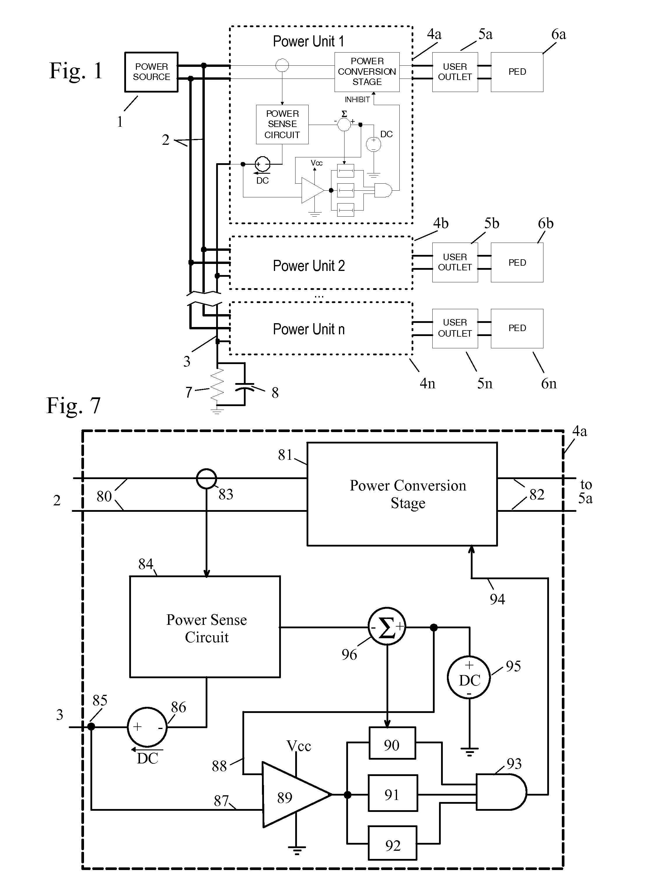
This application claims one or more inventions which were disclosed in the following U.S. Provisional Applications: No. 61/610,775, filed Mar. 14, 2012, entitled “Load Distribution System and Power Management System and Method”; No. 61/611,204, filed Mar. 15, 2012, entitled “Power Management System using Power Supplies Adapted To Use Tri-State Power Management Signals”; No. 61/611,713, filed Mar. 16, 2012, entitled “Load Distribution System and Power Management System and Method”; and No. 61/616,078, filed Mar. 27, 2012, entitled, “Power Management System using Power Supplies Adapted To Use Tri-State Power Management Signals”. The benefit under 35 USC §119(e) of the United States provisional application is hereby claimed, and the aforementioned application is hereby incorporated herein by reference. 1. Field of the Invention The invention pertains to the field of power supplies. More particularly, the invention pertains to a system and method for power management and load distribution. 2. Description of Related Art Electronic systems are often deployed where a plurality of end user nodes are serviced via a power system where there is not enough power available to allow simultaneous operation of all nodes. In an aircraft system, the power source is typically 115V 400 Hz AC generated by one or more engine-powered generators, or supplied by an Auxiliary Power Unit (APU) or battery-powered inverter when the aircraft is on the ground. The available power from the power source is limited by the total output of the generator(s) or APU or inverter, and by demands on the power source by the aircraft's own systems. Increasingly there is a demand for passengers to be able to hook up their own electronic devices in flight, such as laptop computers or media players, etc. These devices usually expect a voltage of 120-240VAC at 50-60 Hz, so power converter units are required to provide power at an appropriate voltage and frequency to a power outlet into which the passenger can plug his or her device. Airlines would like to provide under-seat outlets to allow all of the passengers to plug such devices in for use, but the total current drawn if all passengers in a large jet were to simultaneously plug in laptop computers would exceed the total available for such use. In some present systems outlets which are not currently in use are disabled when a total measured power drawn by enabled outlets exceeds a certain threshold. This threshold is typically set to 200 watts or so below the maximum desired load limit on the branch circuit so that the last user will not cause an overload. This “buffer” power is usually wasted capacity, since a typical user may only need half that amount or less. Once that limit is reached, subsequent users are simply denied any power at all, even though they may have paid “full fare” for their ticket. Various methods have been developed in the prior art to monitor delivered power and then deny service to new subscribers, or deny power to existing subscribers, effectively removing them from the network. To date, these methods are either administered from a central power distribution unit (PDU), or are set up in such a way that they are not easily adaptable or scalable to various deployment scenarios. Legacy systems often employ a centralized power management scheme where power is monitored in a Master Control Unit (MCU) and when the MCU determines delivered power is reaching the limits of what is available for that branch, it issues a signal to all units on that branch which allows existing users to continue to receive power, but does not allow new users to receive power. This signal also provides a third state that forces all units on the branch to shut down. This system has proven to be an impediment to passenger/customer satisfaction in that significant portions of passengers may be denied power during a flight. The power management system of the invention allows precise power control and easy adaptability for distributed power management from a power source to multiple users served by a plurality of power units, where there are limitations on the amount of power available to the power units from the power source. Each power unit in the system uses a monitor bus to monitor total power usage on a branch to which the power unit is assigned, allowing power to be delivered if it won't result in the branch current being exceeded, and denying access if it would. Each power unit adds a signal to the monitor bus proportional to the current it is drawing from the power source. In a first embodiment, the signal added by the power units is an analog current and there is a resistor terminating the monitor bus at the power distribution point or the end of the branch (or elsewhere), which creates a voltage which determines the allowable branch current. The total current draw for all of the power units on the branch is measured by measuring the voltage on the monitor bus. In an alternate embodiment, a pulse train having a repetition rate proportional to current is imposed on the monitor bus by each power unit instead of a current, and the power units determine total current by the signal frequency (number of pulses per second) on the monitor bus. When a potential user plugs into the outlet on a power unit, the power unit recognizes this fact, and if the signal on the monitor bus is below a predetermined amount which represents a total draw below maximum, the inverter turns on. It stays on for a short time and the actual current draw of the power unit is measured and a proportional signal is added to the monitor bus. Assuming the signal on the monitor bus does not rise above the maximum the user continues to receive power. If the power unit is drawing too much current to maintain the total branch current below the maximum, one or more of the power units on the branch turn off, preventing an overload. All other existing users continue to receive uninterrupted AC power. The system is adaptable for implementation in legacy systems that employ Master Control Units which utilize tri-state signals to manage load power. The system will be described herein in terms of power system for a large aircraft such as an airliner, where the limited power available from the aircraft's power system will need to be allocated to outlets used by passengers to power laptop computers and the like, but it will be understood that the system is equally applicable to other applications where a limited power resource needs to be distributed among a plurality of varying loads. Referring to the block diagram of As noted before, the power distribution bus 2 in an aircraft is typically powered at 115VAC 400 Hz, and under-seat power outlets 5 Each of the power units 4 In this embodiment, each power unit 4 The power unit 4 The current in the power conversion stage 81 is measured by a sensor 83, which is input to power sense circuit 84. The example shows sensor 83 sensing current in the input 80 to power conversion stage 81, so that the sensor 83 directly reads current drawn from the power bus 2. It will be understood that the current sensing could also be done on the output 82 of the power conversion stage within the teachings of the invention, although since the output 82 might be at a different voltage, some adjustments might have to be made so that the method correctly controls the current demand on the power bus 2. Power sense circuit 84 has an output to a control input of a controlled DC current source 86, which adds a controlled current to a lead 85 which is connected to monitor bus 3. As explained further below, the current added by current source 86 is controlled by power sense circuit 84 to be proportional to the current drawn by power conversion stage 81 through input 80 from power bus 2. The voltage on monitor bus 3 is input through lead 85, and connects to one input 87 of comparator 89. The other input 88 of comparator 89 is connected to a reference voltage 95. The output of comparator 89 is connected to several timing circuits—in this example shown as timing circuits 90, 91 and 92, although it will be understood that more or fewer circuits may be used as desired. The reason for having multiple timing circuits is to enable the various timing and randomization methods described in the operational discussion below. A current signal from power sense circuit 84 is subtracted from the reference voltage from source 95 in summing junction 96 and the result inputs into timing circuit 90. The outputs of timing circuits 90, 91 and 92 are input into OR-gate 93, so that if any of the timers 90-92 are timed out, the output of OR-gate 93 raises the INHIBIT signal 94, as noted above. If the power monitor bus voltage as measured by comparator 89 reaches the above reference 95, the first internal timing circuit 90 initiates and sets a certain short time delay inversely proportional to the current consumed by that unit as measured by its sensing circuit (for example 10 to 50 ms). If during this time delay the voltage did not drop below maximum allowable limit, the INHIBIT line 94 causes this unit to go into a timeout mode, where its output 82 remains inhibited for a predetermined or randomized amount of time set by the second timing circuit 91, for example, one minute. As an example, assume a 10 ampere (A) branch current limit is required on power bus 2 to prevent a circuit breaker in the power source (master power unit) from tripping. The power units 4 This could be 10 users at 1 A each, or 20 users at 0.5 A each, etc. Any number of subscribers at any potential load will be summed, and the total current draw on power bus 2 is available for each power unit 4 Since the only way to determine what a potential subscriber will draw in his or her device 6 Preferably, a predetermined “headroom” amount will be determined based on typical use which represents how much below the maximum 2.5V the voltage needs to be before the power unit 4 For the purposes of this example, let us say that at the time the user plugs in device 6 Let us suppose at this point that a user plugs another device 6 It should be noted here that rather than power unit 4 With the outlet 5 In one embodiment, power unit 4 The control circuit in each power unit 4 Other methods of managing power when the current on the power bus 2 approaches the maximum are possible within the teachings of the invention. For example, the power unit 4 The power units 4 In another implementation, a random timer can be used to delay the shutdown of the power unit. When the current limit level is reached, each unit would have a random time delay before it shut down. So the unit with the shortest time delay would turn off first, reducing the load. If the reduction was not enough, a second unit might turn off before the current is reduced sufficiently, preventing any more units from shutting down. In still another implementation, the current limit threshold can have a small random signal imposed on it. This means that when the system is close to the current limit point, one power unit will randomly cross the limit first and shut down, lowering the total current draw. If the reduction is not enough, a second unit might shut down before the overall draw is reduced to below the limit, preventing any more units from shutting down. If after shut down of one unit the total node power still reaches its limit, the unit with the next highest power level and accordingly the next shortest shutdown delay will be the next one to inhibit its output. As the result of this process, the total node power is always assured to be below the maximum allowable limit. Each inhibited unit will return to active mode after a pre-determined or random time delay set by a second timing circuit (for example, one minute) and its third internal timing circuit will keep that unit “safe” for another pre-determined or random time (for example, five minutes). If after the return of previously inhibited unit to active mode the total node power again reaches its allowable limit, this time another unit which consumes highest current which sets the shortest shutdown delay time, will be the first one to inhibit. In another possible implementation, the reference voltage level in each unit is inversely proportional to the power consumed by the unit. As the result, when the total power consumed by all units on a given power node reaches a certain pre-determined threshold, the power monitor bus voltage will first reach the reference voltage level in the unit that consumes the lowest amount of power and which probably has an already charged PED. In another possible implementation, the reference voltage in each unit is the same value and a non-synchronized ramp voltage is imposed on top of this reference. When the power monitoring bus reaches its allowable limit, the non-synchronized nature of the ramp will cause a randomizing effect as to which unit is shut off for power management purposes. Once a unit is inhibited, the total node power will most likely drop below the maximum limit and the remaining units will continue to operate. The unit that was shut down will be re-enabled after a predetermined or random time delay set by an internal timing circuit (for example, one minute). Once it is re-enabled, if the monitoring bus reaches its allowable limit all units on the bus will once again be subject to possible shut down, with the unit whose reference+ramp reaches the shutdown threshold first being the one that is shut off. The unit may have a modification to be installed in high priority locations such as in first class seats, with a higher reference voltage level to assure these “priority” passengers will always get power (provided their net amount does not exceed a set limit for a given power branch), while the rest of the seats would get only remaining power when it's available. In another possible implementation, individual power units 4 In another possible implementation, end users can be provided with a choice of either an AC powered outlet, or a low voltage USB power port powered by the power conversion stage 81 or by a separate power conversion unit (not shown). In this implementation, the AC outlet can be subjected to power management with any of the aforementioned schemes. The USB power port can be set up to either be powered (or unpowered) in conjunction with its partnered AC outlet, or the USB port can be set to remain on, even if its associated AC outlet is subject to power management. This is another manner in which the carrier can provide preferential treatment to low power users who are the typical consumers of airline provided, on board content. The operation of the system allows all users access to the power by periodically rotating enabled inverters. This system requires no “buffer” power level, so it typically allows an extra person to have full access to power. If additional users plug in, exceeding the branch capacity, users are dropped for a short time, as described above. In most cases a passenger whose outlet is temporarily disabled would not even notice this as they are likely operating from internal battery power during this short interval. In another possible implementation, the “zero current” reference voltage could be a positive or negative voltage, and the voltages could be pulled high or low as units sum their currents. Referring to The current in the power conversion stage 81 is measured by a sensor 83, which is input to power sense circuit 84. The example shows sensor 83 sensing current in the input 80 to power conversion stage 81, so that the sensor 83 directly reads current drawn from the power bus 2. It will be understood that the current sensing could also be done on the output 82 of the power conversion stage within the teachings of the invention, although since the output 82 might be at a different voltage, some adjustments might have to be made so that the method correctly controls the current demand on the power bus 2. Power sense circuit 84 has an output 108 which provides a voltage proportional to the sensed current to a control input of a voltage-to-frequency converter 101. The voltage-to-frequency converter 101 converter produces short pulses (1 μS, as an example) and impresses these pulses on the monitor bus 3 through a diode or a tri-state driver 105. The frequency (number of pulses per second) output by the voltage-to-frequency converter 101 would be proportional to the voltage 108 with a scale factor, for example, of 1 kHz per ampere of current measured by sensor 83. The signal on the monitor bus 3, which would comprise all of the pulses output from the pulse unit 4 Thus, if there were ten power units 4 When the total current on bus 2 reaches the critical point (for example, 15 Amps corresponds to 15 kHz), the microcontroller 102 detects this by counting the pulses per second on the bus, detecting the pulses exceed and raises a voltage 107 which is input to the power conversion stage 81 as INHIBIT input 94. This shuts down the converter 81 for a fixed amount of time to reduce the total bus 2 current. Since all of the microprocessors in the power units 4 The operation of the system will now be described with reference to the time marks t0-t7 in The system continues on from that point, as loads are added to and removed from the bus 2. In another possible implementation, the analog share bus is implemented digitally by any one of a number of common communications buses, such as CAN bus or Ethernet. Each unit would report its load current, and each unit could then know all the currents. Any type of algorithm could be implemented to drop of users for load shedding. The first user to be dropped could be the user who has been on the longest time, the user who has consumed the least watt-hours, the user who has consumed the most watt-hours, etc. Legacy aircraft cabin power systems employ a centrally generated tri-state signal that is daisy chained between units. The power units 21 The legacy systems used the TS line to control the power units 21 While these are the usual modes which can be commanded by MCU 20 on the tri-state control line TS, the actual correspondence between the state and the mode may differ. The following table presents the different possibilities for the tri-state signal. It is possible within the teachings of the invention to adapt the system of the invention to work in an aircraft cabin wired for a legacy power management system using tri-state control. In adapting the system of the invention to legacy systems with tri-state control, the adapted system is set up to reinterpret the existing tri-state signals, as follows. In this adapted system, power units 31 The last output connector 23 Because conductor TS is used as the monitor bus 3, it must be isolated from the tri-stage control signals from MCU 20 during normal operation. This isolation is done in the head end connector 30, and the different scenarios from table 1, above, require different embodiments of the head end connector 30. These embodiments are shown in This scenario uses the head end connector 30 shown in A “low” signal on the power management bus TS will pull the monitor bus 3 to zero volts plus a diode drop, and circuitry internal to the power units 33 This scenario uses the head end connector 30 shown in If the tri-state signal on TS is set “high”, this will force a high voltage on monitor bus 3, and circuitry internal to the power units 33 This is the same situation as scenario 1A, except that the functions of “high” and “open” are reversed by the MCU 20 for operating the legacy system in local control and power management mode. Since the power units 33 This scenario uses the head end connector 30 as shown in An “open” signal from the tri-state power management bus TS will force the head end connector 30 circuit 60 to pull the power management bus TS below 1V and thereby force all power units 33 This is the same situation as scenario 1B, except that the functions of “low” and “open” are reversed by the MCU 20 for operating the legacy system in local control and power management mode. Since the power units 33 This is the same situation as scenario 2B, except that the functions of “low” and “high” are reversed by the MCU 20 for operating the legacy system in local control and power management mode. Since the power units 33 Accordingly, it is to be understood that the embodiments of the invention herein described are merely illustrative of the application of the principles of the invention. Reference herein to details of the illustrated embodiments is not intended to limit the scope of the claims, which themselves recite those features regarded as essential to the invention. A power management system for distributed power management from a power source to a plurality of power units, using a monitor bus to monitor total power usage on a branch to which the power unit is assigned, allowing power to be delivered if it won't result in a maximum current draw from the power source being exceeded, and denying access if it would. Each power unit adds a signal to the monitor bus proportional to the current it is drawing from the power source. 1. A load distribution system and power management system for distributing electrical power from a power source having a maximum current draw to a plurality of user devices, comprising:
a) a power bus coupled to the power source; b) a monitor bus; c) a plurality of power units coupled to the power bus and the monitor bus, each power unit comprising:
i) a power conversion stage having an input coupled to the power bus, an inhibit input and an output for connection of a user device; ii) a current sensor sensing current drawn from the power bus by a user device connected to the output of the power conversion stage; iii) a power sense circuit having an input coupled to the current sensor, and an output coupled to the monitor bus, the power sense circuit putting a signal on the monitor bus proportional to the current sensed by the current sensor, such that the total signal on the monitor bus is proportional to the total current being drawn from the power bus by the power conversion stages of the plurality of power units; and iv) a comparator having an input coupled to the monitor bus for comparing the total signal on the monitor bus to a reference, and an output coupled to the inhibit input of the power conversion stage; such that when the total signal on the monitor bus rises to a selected value relative to the reference, the comparator output causes a signal on the inhibit input of the power conversion stage, thus causing the power to the user device to be disconnected; and the reference being chosen such that when the total signal on the monitor bus reaches the reference, the power conversion units in the plurality of power units are drawing the maximum current draw from the power source on the power bus. 2. The load distribution system and power management system of the signal put on the monitor bus by each power unit is a current proportional to the current drawn from the power bus by the power unit; the monitor bus has a reference resistor creating a voltage on the monitor bus proportional to current on the monitor bus; the reference is a voltage; and the comparator is a voltage comparator. 3. The load distribution system and power management system of the signal put on the monitor bus by each power unit is a train of pulses having a frequency proportional to the current drawn from the power bus by the power unit, such that the monitor bus has a signal representing a total of the trains of pulses from each power unit, thus having a frequency proportional to total current drawn by the power units from the power bus; and the reference is a frequency. 4. The load distribution system and power management system of 5. The load distribution system and power management system of 6. The load distribution system and power management system of 7. The load distribution system and power management system of 8. The load distribution system and power management system of 9. A power unit for a load distribution and power management system for distributing electrical power from a power source having a maximum current draw to a plurality of user devices, the system comprising a power bus coupled to the power source and a monitor bus; the power unit comprising:
a) a power conversion stage having an input coupled to the power bus, an inhibit input and an output for connection of a user device; b) a current sensor sensing current drawn from the power bus by a user device connected to the output of the power conversion stage; c) a power sense circuit having an input coupled to the current sensor, and an output coupled to the monitor bus, the power sense circuit putting a signal on the monitor bus proportional to the current sensed by the current sensor, such that the total signal on the monitor bus is proportional to the total current being drawn from the power bus by the power conversion stages of the plurality of power units; and d) a comparator having an input coupled to the monitor bus for comparing the total signal on the monitor bus to a reference, and an output coupled to the inhibit input of the power conversion stage; such that when the total signal on the monitor bus rises to a selected value relative to the reference, the comparator output causes a signal on the inhibit input of the power conversion stage, thus causing the power to the user device to be disconnected; and the reference being chosen such that when the total signal on the monitor bus reaches the reference, the power conversion units in the plurality of power units are drawing the maximum current draw from the power source on the power bus. 10. The power unit of the signal put on the monitor bus by each power unit is a current proportional to the current drawn from the power bus by the power unit; the monitor bus has a reference resistor creating a voltage on the monitor bus proportional to current on the monitor bus; the reference is a voltage; and the comparator is a voltage comparator. 11. The power unit of the signal put on the monitor bus by each power unit is a train of pulses having a frequency proportional to the current drawn from the power bus by the power unit, such that the monitor bus has a signal representing a total of the trains of pulses from each power unit, thus having a frequency proportional to total current drawn by the power units from the power bus; and the reference is a frequency. 12. The power unit of 13. The power unit of 14. The power unit of 15. A method of operating a load distribution and power management system for distributing electrical power from a power source having a maximum current draw to a plurality of user devices, the system comprising a power bus coupled to the power source; a monitor bus; and a plurality of power units coupled to the power bus and the monitor bus, each power unit comprising a power conversion stage having an input coupled to the power bus and an output for connection of a user device, each power unit putting a signal on the monitor bus proportional to current drawn from the power bus by a user device on the output of the power conversion stage of the power unit; a selected total signal on the monitor bus indicating the point at which the power conversion units in the plurality of power units are drawing the maximum current draw from the power source on the power bus, wherein the method comprises:
a) when a user connects a user device to the output of the power conversion stage of a power unit, the power unit supplying power from the power bus to the user device; b) the power unit sensing the signal on the monitor bus after supplying power to the user device; and c) if, after the power unit supplies power to the user device, the signal on the monitor bus is greater than a value related to the selected monitor bus reference, the power unit disconnecting power to the user device. 16. The method of 17. The method of 18. The method of 19. The method of 20. The method of 21. The method of 22. The method of 23. The method of 24. The method of 25. The method of REFERENCE TO RELATED APPLICATIONS
BACKGROUND OF THE INVENTION
SUMMARY OF THE INVENTION
BRIEF DESCRIPTION OF THE DRAWING
DETAILED DESCRIPTION OF THE INVENTION
Embodiment 1
DC Current Monitor Bus Control
Embodiment 2
Pulse Rate Monitor Bus Control
Embodiment 3
Control by Digital Signals on Digital Monitor Bus
Tri-State Signal Interface
Tri-state Signal Control Scenarios Commanded Scenario Scenario Scenario Scenario Scenario Scenario Module Mode 1A 1B 2A 2B 3A 3B Local Control Open Open High High Low Low Power Management High Low Open Low Open High Shut Down Low High Low Open High Open Interpretation of MCU Generated Tri-state Control Signals Control Mode Legacy Operation Present System Operation Local Control Normal operation - Normal operation - allow new allow new users users up to the point where Power Management Do not allow new power management mode is users entered as determined by the power monitor bus. Shut Down Units shut down Units shut down Scenario 1A
“Normal Operation” is Denoted by Either “High” or “Open” Tri-State Signal, Shut Down on “Low” Tri-State Signal
Scenario 1B
“Normal Operation” is Denoted by Either “Low” or “Open” Tri-State Signal, Shut Down on “High” Tri-State Signal
Scenario 2A
“Normal Operation” Denoted by a “Open” or “High” Tri-State Signal, Shut Down on “Low” Tri-State Signal
Scenario 2B
“Normal Operation” Denoted by a “High” or “Low” Tri-State Signal, Shut Down on “Open” Tri-State Signal
Scenario 3A
“Normal Operation” Denoted by a “Low” or “Open” Tri-State Signal, Shut Down on “High” Tri-Stage Signal
Scenario 3B
“Normal Operation” Denoted by a “Low” or “High” Tri-State Signal, Shut Down on “Open” Tri-State Signal