SHEET PROCESSING APPARATUS AND IMAGE FORMING APPARATUS
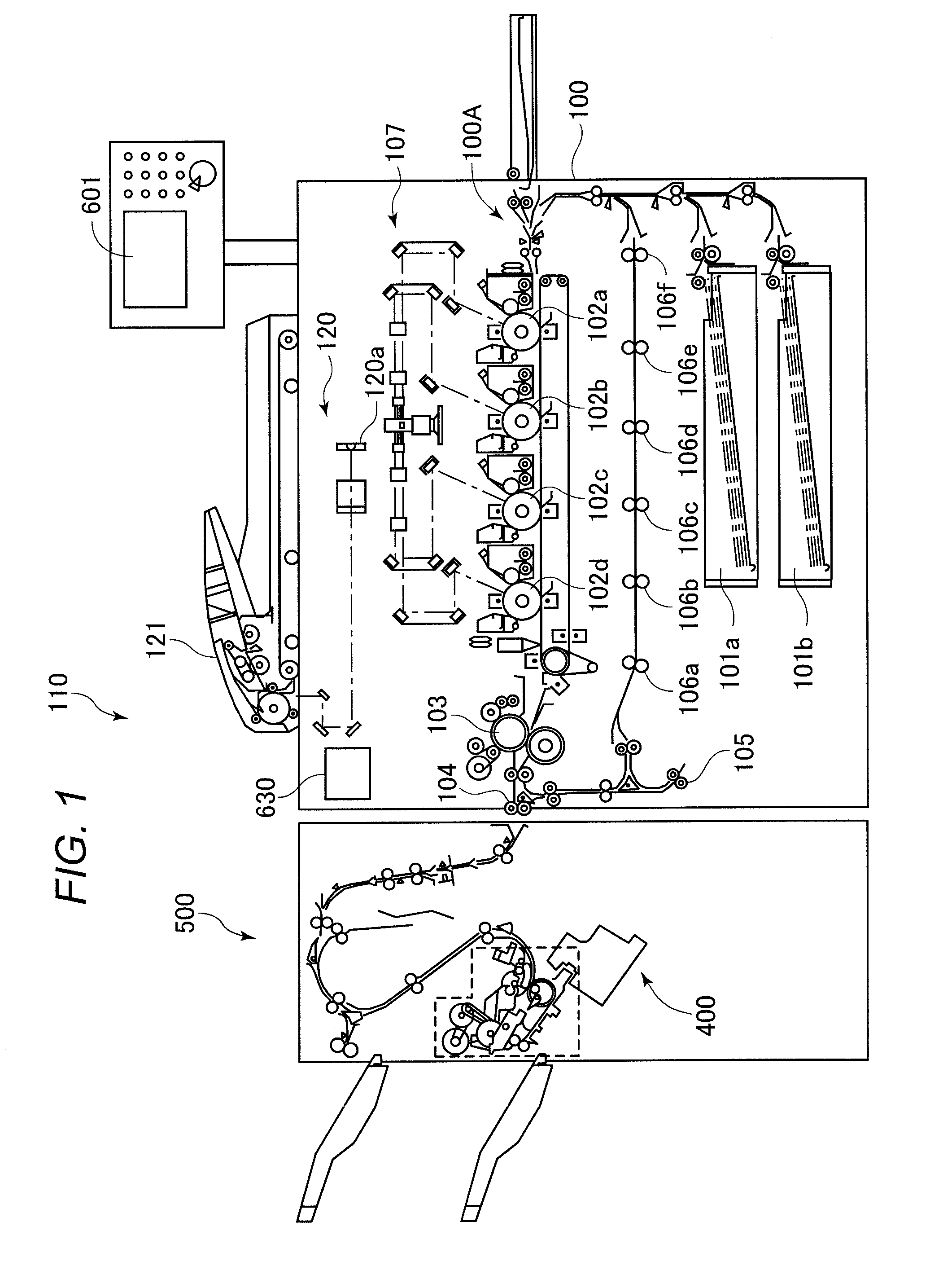
1. Field of the Invention The present invention relates to a sheet processing apparatus and an image forming apparatus. 2. Description of the Related Art Hitherto, as an image forming apparatus such as a copying machine, a laser beam printer, a facsimile machine, and a multifunction peripheral having functions of those apparatus, there is an image forming apparatus including a sheet processing apparatus configured to perform processes such as a binding process and a sorting process on sheets having images formed thereon. Further, there is widely known an image forming apparatus (image forming system) including the sheet processing apparatus connected to a discharge port formed in a main body of the image forming apparatus so as to automatically perform the above-mentioned processes on the sheets on-line. As the sheet processing apparatus, there is widely used a sheet processing apparatus configured to perform the processes such as a binding process on a sheet bundle, which is formed by stacking a plurality of sheets onto an intermediate processing tray provided inside the sheet processing apparatus. For example, there is an apparatus configured to bind the sheet bundle by a binding unit at the time of the binding process, discharge the bound sheet bundle from the intermediate processing tray by a bundle discharge roller pair serving as a rotary member pair, and to stack the discharged sheet bundle onto a stacking tray (see Japanese Patent Application Laid-Open No. 2012-96869). When a first sheet is to be stacked onto the intermediate processing tray, an upper bundle discharge roller of the bundle discharge roller pair is lowered so as to nip the sheet between the upper bundle discharge roller and a lower bundle discharge roller. Then, the upper bundle discharge roller is rotated in a reverse direction so as to convey the sheet toward a trailing edge stopper provided on the intermediate processing tray. When a second or subsequent sheet is to be stacked, the upper bundle discharge roller is moved upwardly so as not to interfere with the succeeding sheet sliding toward the trailing edge stopper along an upper surface of the sheet, which is already stacked on the intermediate processing tray. When the sheet bundle is bound and the bound sheet bundle is to be discharged, the upper bundle discharge roller is lowered so as to nip the sheet bundle between the upper bundle discharge roller and the lower bundle discharge roller, to thereby discharge the sheet bundle. When the first sheet is to be stacked onto the intermediate processing tray in the related-art sheet processing apparatus, the bundle discharge roller pair is rotated in the direction opposite to the rotational direction at the time of discharging the sheet onto the stacking tray. In this case, the drive configuration of the bundle discharge roller pair is set so that the drive is first transmitted to the lower bundle discharge roller and then transmitted to the upper bundle discharge roller via a drive transmission unit including a plurality of gears. That is, when the sheet bundle is to be discharged onto the stacking tray in the related-art sheet processing apparatus, the lower bundle discharge roller is first rotated, and the rotation of the lower bundle discharge roller is then transmitted via the drive transmission unit so that the upper bundle discharge roller is rotated. In the case of this drive configuration, when the bound sheet bundle is to be discharged onto the stacking tray, during the rotation of the lower bundle discharge roller in the sheet discharge direction, backlashes of the drive transmission unit may cause a delay in the drive transmission to the upper bundle discharge roller. As a result, the start of rotation of the upper bundle discharge roller is delayed as compared to the lower bundle discharge roller. Thus, when the sheet bundle is to be discharged, a lower sheet of the sheet bundle, which is held in contact with the lower bundle discharge roller, is conveyed but, due to the delay in the start of rotation of the upper bundle discharge roller, an upper sheet of the sheet bundle, which is held in contact with the upper bundle discharge roller, is not conveyed at this time, with the result that the upper sheet is distorted. When the drive is then transmitted to the upper bundle discharge roller, the sheet bundle is conveyed under a state in which the upper sheet is distorted. When the sheet bundle is conveyed in this state, the binding portion of the sheet bundle passes through the bundle discharge roller pair without a relief region for the distorted portion of the upper sheet. The distorted portion is crushed by the bundle discharge roller pair, with the result that creases may be generated in the binding portion. To prevent the generation of creases, there is conceived a method of reducing a press-contact force of the bundle discharge roller pair to suppress the distortion of the upper sheet when the bundle discharge roller pair abuts against the sheet bundle and conveys the sheet bundle. When the conveyance force of the bundle discharge roller pair is excessively reduced, however, in a case of a thick sheet bundle, the conveyance force is insufficient, which may cause slippage between the bundle discharge rollers and the sheet bundle during the conveyance of the sheet bundle by the bundle discharge roller pair. When the sheet bundle is slipped, marks of slippage are generated on the surface of the sheet bundle by the bundle discharge roller pair, with the result that the quality of a product may be degraded. The present invention has been made in view of the above-mentioned circumstances, and provides a sheet processing apparatus capable of preventing degradation of the quality of a product. According to one example of the present invention, there is provided a sheet processing apparatus, including: a sheet conveying portion configured to convey the sheet; a sheet stacking portion on which a sheet conveyed by the sheet conveying portion is stacked; a regulating portion configured to regulate a position of the sheet on the sheet stacking portion; a binding portion configured to bind a plurality of sheets regulated by the regulating portion; a rotary member pair having a first rotary member and a second rotary member, the rotary member pair configured to convey the sheet toward the regulating portion through rotation in a first direction, and configured to convey a sheet bundle, which is bound by the binding portion, through rotation in a second direction opposite to the first direction; a moving portion configured to move the second rotary member to a separation position, at which the second rotary member is separated away from the first rotary member, after the rotary member pair conveys the sheet toward the regulating portion, and configured to move the second rotary member from the separation position to a nipping position, at which the second rotary member and the first rotary member nip the sheet bundle, before the rotary member pair conveys the bound sheet bundle; a drive portion configured to drive the first rotary member and the second rotary member; and a control portion configured to control the drive portion and the moving portion so as to rotate the rotary member pair in the second direction after the second rotary member is moved to the separation position and before the second rotary member is moved to the nipping position. According to other example of the present invention, there is provided a sheet processing apparatus, including: a sheet stacking portion on which a sheet is stacked; a binding portion configured to bind a plurality of sheets stacked on the sheet stacking portion; a rotary member pair configured to convey a sheet toward the binding portion through rotation in a first direction, and configured to convey a bound sheet bundle, which is bound by the binding portion, through rotation in a second direction opposite to the first direction; a changing portion configured to change a state of the rotary member pair into a state in which the rotary member pair does not nip a sheet after the rotary member pair conveys the sheet toward the binding portion, and thereafter to change the state of the rotary member pair into a nipping state in which the rotary member pair nips the bound sheet bundle; a drive portion configured to drive the rotary member pair; and a control portion configured to control the drive portion so as to rotate the rotary member pair in the second direction while the state of the rotary member pair is in the state in which the rotary member pair does not nip a sheet. According to other example of the present invention, there is provided an image forming apparatus, including: an image forming portion; a sheet stacking portion on which a sheet having an image formed thereon by the image forming portion is stacked; a regulating portion configured to regulate a position of the sheet on the sheet stacking portion; a binding portion configured to bind a plurality of sheets regulated by the regulating portion; a rotary member pair having a first rotary member and a second rotary member, the rotary member pair configured to convey the sheet toward the regulating portion through rotation in a first direction, and configured to convey a sheet bundle, which is bound by the binding portion, through rotation in a second direction opposite to the first direction; a moving portion configured to move the second rotary member to a separation position, at which the second rotary member is separated away from the first rotary member, after the rotary member pair conveys the sheet toward the regulating portion, and configured to move the second rotary member from the separation position to a nipping position, at which the second rotary member and the first rotary member nip the sheet bundle, before the rotary member pair conveys the bound sheet bundle; a drive portion configured to drive the first rotary member and the second rotary member; and a control portion configured to control the drive portion and the moving portion so as to rotate the rotary member pair in the second direction after the second rotary member is moved to the separation position and before the second rotary member is moved to the nipping position. Further features of the present invention will become apparent from the following description of exemplary embodiments with reference to the attached drawings. Now, exemplary embodiments of the present invention are described in detail with reference to the drawings. The copying machine main body 100 includes sheet feeding cassettes 101 The monochrome/color copying machine 110 forms an image of an original (not shown) on the sheets as follows. First, the image of the original conveyed by the original conveying device 121 is read with an image sensor 120 Next, the toner images of those four colors are transferred onto the sheet fed from the sheet feeding cassette 101 In a mode of forming images on both sides of the sheet, the sheet is delivered from the fixing portion 103 to reverse rollers 105. Then, the reverse rollers 105 is reversed at a predetermined timing so that the sheet is conveyed toward duplex conveying rollers 106 (106 The finisher 500 sequentially introduces the sheets discharged from the copying machine main body 100, and performs a process of aligning and bundling the plurality of introduced sheets into one bundle, and a punching process of punching a hole in the vicinity of a trailing edge of each of the introduced sheets. Further, the finisher 500 performs, for example, a stapling process (binding process) of stapling a trailing edge side of the sheet bundle. The finisher 500 includes a stapling portion 400 serving as a binding portion configured to staple the sheets. As illustrated in After the misalignment of the sheet in the width direction is corrected, the sheet is then conveyed by conveying rollers 504, and reaches a buffer roller pair 505. After that, when the sheet is discharged onto an upper tray 515, a drive portion (not shown) such as a solenoid causes an upper path switching member 506 to rotate clockwise. With this, the sheet is guided to an upper conveying path R2, and is discharged by upper discharge rollers 507 onto the upper tray 515. When the sheet conveyed by the buffer roller pair 505 is not discharged onto the upper tray 515, the sheet is guided to a bundle conveying path R3 by the upper path switching member 506 illustrated by a solid line. After that, conveying rollers 508 and a bundle conveying roller pair 509 cause the sheet to sequentially pass through the conveying path, and the sheet is conveyed to a discharge path R4. The sheet conveyed to the discharge path R4 is then sequentially conveyed by a lower discharge roller pair 513 serving as a sheet conveying portion onto an intermediate processing tray 409 serving as a sheet stacking portion configured to process the sheet bundle formed by stacking the sheets in alignment state. On the intermediate processing tray, a predetermined number of the conveyed sheets are aligned by a returning portion including a draw-in paddle 414 and a belt roller 416 illustrated in When a preceding sheet bundle is being aligned or bound on the intermediate processing tray, a predetermined number of first sheets for forming a succeeding sheet bundle are superimposed one on top of the other through forward and reverse rotation of the buffer roller pair 505. After the preceding sheet bundle is discharged, the predetermined number of first sheets are conveyed to the intermediate processing tray 409. The process of superimposing the predetermined number of first sheets for forming the succeeding sheet bundle one on top of the other is a buffering process to be performed for the purpose of securing a processing time of the preceding sheet bundle on the intermediate processing tray. Subsequent sheets for forming the succeeding sheet bundle are sequentially conveyed to the intermediate processing tray 409 one by one. Next, the sheet bundle aligned on the intermediate processing tray is bound as appropriate by a stapler 300 serving as a binding portion. After that, the sheet bundle is discharged by a bundle discharge roller pair 514 onto the lower stacking tray 516. The stapler 300 is freely movable in the width direction orthogonal to the sheet conveying direction (hereinafter referred to as “depth direction”). The stapler 300 is capable of binding a plurality of points on the trailing edge portion of the sheet bundle. The image signal control portion 634 outputs the data to a printer control portion 635, and the printer control portion 635 outputs data from the image signal control portion 634 to an exposure control portion (not shown). Note that, an image reader control portion 633 outputs an image of an original read by the image sensor 120 The operation portion 601 includes a plurality of keys for setting various functions of image formation, a display portion for displaying setting conditions, and the like. The operation portion 601 outputs key signals corresponding to operations of the keys by a user to the CPU circuit portion 630, and in response to signals from the CPU circuit portion 630, displays information pieces corresponding to the signals on the display portion. Based on the control programs stored in the ROM 631 and the settings from the operation portion 601, the CPU circuit portion 630 controls the image signal control portion 634, and the original conveying device 121 (see In this embodiment, the finisher control portion 636 is mounted to the finisher 500, and drives and controls the finisher 500 through exchange of information with the CPU circuit portion 630. The finisher control portion 636 may be arranged integrally with the CPU circuit portion 630 on the copying machine main body side so that the finisher 500 is directly controlled from the copying machine main body. Next, a configuration of the stapling portion 400 including the intermediate processing tray 409 is described. As illustrated in The intermediate processing tray 409 includes, at its middle portion, a pair of alignment plates 440 configured to move independently of each other along the width direction relative to the intermediate processing tray 409 and abut against both side edges of the sheet stacked onto the intermediate processing tray 409, to thereby align the sheet. Further, as illustrated in When a trailing edge of the sheet conveyed onto the intermediate processing tray passes through a nip of the lower discharge roller pair 513 serving as the sheet conveying portion, the trailing edge drop members 412 are moved downwardly and biased toward the intermediate processing tray 409. After that, through counterclockwise rotation of the draw-in paddle 414 and the belt roller 416, the upstream edge of the sheet in the discharge direction (upstream edge in a conveying direction) is brought into abutment against the trailing edge stopper 417, and thus the position of the trailing edge of the sheet in the discharge direction is aligned (regulated). The draw-in paddle 414 is arranged above the intermediate processing tray 409, and is rotatable about a paddle drive shaft 413. As illustrated in The trailing edge drop member HP sensor S1 provided to the trailing edge drop member holder 421 detects the position of the trailing edge drop member HP flag 420, and thus the finisher control portion 636 controls the positions of the trailing edge drop members 412. The cams 410 are provided corresponding to the respective trailing edge drop members 412, and all the cams 410 have the same phase. Thus, through the rotation of the cams 410 by the trailing edge drop member drive motor M2, the trailing edge drop members 412 can be lowered at the same time. The home positions (HPs) of the trailing edge drop members 412 correspond to positions illustrated in As illustrated in Due to the configuration that the upper bundle discharge rollers 514 When the upper openable/closable guide 401 is pivoted upwardly, the sheet conveyed from the lower discharge roller pair 513 is slid down along a stacking surface of the intermediate processing tray 409 or a sheet stacked on the intermediate processing tray 409 due to the draw-in paddle 414 and the inclination of the intermediate processing tray 409. After that, the sheet thus slid down is conveyed (transported) through the counterclockwise rotation of the belt roller 416, and is stopped when the trailing edge (upstream edge in the discharge direction) is brought into abutment against the trailing edge stopper 417. After that, the sheet is aligned in the width direction on the intermediate processing tray 409. This operation is performed every time a sheet is conveyed onto the intermediate processing tray 409 until the sheet bundle is formed. After that, the sheet bundle formed of the plurality of sheets is subjected to a process such as binding. When the process for the sheet bundle is finished on the intermediate processing tray 409, the upper openable/closable guide 401 is pivoted downwardly. Thus, the upper bundle discharge rollers 514 Next, a configuration for opening and closing the upper openable/closable guide 401 and a configuration for driving the bundle discharge roller pair 514 are described with reference to As illustrated in In this embodiment, the opening/closing links 404, the link rotating plates 406, the upper openable/closable guide 401, the opening/closing motor M1 for the upper openable/closable guide, and the like serve as a moving portion 400A configured to move the upper bundle discharge rollers 514 As illustrated in Next, the drive of the bundle discharge roller pair 514 is described. As illustrated in A drive gear 427 is provided to the other end portion of the roller shaft 514 An idler pulley 433 is provided coaxially with the idler pulley 431. A timing belt 437 is looped between the idler pulley 433 and a drive pulley 435 attached to one end of a roller shaft 514 In this embodiment, through the forward rotation of the bundle discharge motor M3, the bundle discharge roller pair 514 is rotated in the sheet discharge direction, to thereby discharge the sheet bundle from the intermediate processing tray 409. Through the reverse rotation of the bundle discharge motor M3, the bundle discharge roller pair 514 is rotated in the reverse direction, to thereby convey the sheet, which is conveyed from the lower discharge roller pair 513, to the trailing edge stopper 417. In this embodiment, as illustrated in A solenoid link 443 configured to press the stiffness imparting member attaching plate 442 and a link pivot shaft 444 configured to move the solenoid link 443 are attached to the stiffness imparting member biasing solenoid 445. When the stiffness imparting member biasing solenoid 445 is turned ON, the link pivot shaft 444 is pulled, and the solenoid link 443 is pivoted along with the pull of the link pivot shaft 444, to thereby press the stiffness imparting member attaching plate 442. Thus, the stiffness imparting member attaching plate 442 is moved from a position illustrated in In this embodiment, the stiffness imparting members 441 protrude after the sheet bundle is bound. After the stiffness imparting members 441 protrude, the upper openable/closable guide 401 is pivoted downwardly so as to bring the upper bundle discharge rollers 514 That is, in this embodiment, the stiffness imparting members 441 protrude under a state in which the upper openable/closable guide 401 is pivoted upwardly and the upper bundle discharge rollers 514 Next, an operation to be performed in a binding job of the stapling portion according to this embodiment is described with reference to The lower discharge sensor S3 detects the sheet P1 and switches ON (“Y” in Step S802). Based on this detection, the finisher control portion 636 then activates the trailing edge drop member drive motor M2 so as to lower the trailing edge drop members 412 as illustrated in Next, as illustrated in The above description is directed to the operation to be performed in a case where no preceding sheet bundle is being processed on the intermediate processing tray. In a case where a preceding sheet bundle is being processed on the intermediate processing tray, however, a predetermined number of first sheets for forming a succeeding sheet bundle are conveyed in a state of being superimposed one on top of the other. Also in this case, the operation and control are performed in the same manner as in the case where a first single sheet is conveyed onto the intermediate processing tray. Next, a second sheet P2 is conveyed from the lower discharge roller pair 513 onto the intermediate processing tray 409. At this time, as illustrated in When the alignment of the trailing edge of the sheet P2 is finished, the finisher control portion 636 then operates the alignment plates 440 so as to align the sheet P2 in the width direction similarly to the first sheet P1. After that, a sheet succeeding the second sheet is stacked onto the intermediate processing tray 409 as described above (S806). When the last sheet is conveyed onto the intermediate processing tray (“Y” in Step S807), the last sheet is aligned so that a sheet bundle PA is formed. After that, the sheet bundle PA is bound by the stapler 300 (S808). When the binding process is finished, the finisher control portion 636 then turns ON the stiffness imparting member biasing solenoid 445 (S809) so as to protrude the stiffness imparting members 441 with respect to the lower bundle discharge rollers 514 When the first sheet P1 is conveyed to the belt roller 416, the bundle discharge motor M3 is stopped after rotating the lower bundle discharge rollers 514 Next, the finisher control portion 636 temporarily stops the bundle discharge motor M3 under a state in which the backlashes are eliminated (S811). After that, the upper openable/closable guide 401 is pivoted downwardly (S812). Thus, as illustrated in In this embodiment, the stiffness imparting members 441 are protruded with respect to the lower bundle discharge rollers 514 Due to the configuration that the sheet bundle PA is lifted, when the lower bundle discharge rollers 514 As described above, in this embodiment, the backlashes of the drive transmission portion 400B are eliminated before the upper openable/closable guide 401 is pivoted downwardly. Due to the configuration that the backlashes of the drive transmission portion 400B are eliminated in this manner, when the sheet bundle is discharged, delay in the drive transmission to the upper bundle discharge rollers 514 That is, in this embodiment, the backlashes of the drive transmission portion 400B are eliminated before the sheet bundle PA is discharged, and the bundle discharge roller pair 514 is rotated in the second direction under a state in which the backlashes of the drive transmission portion 400B are eliminated. Thus, it is possible to prevent generation of creases at the binding portion of the sheet bundle, and to therefore prevent degradation of the quality of a product, which may be caused by the backlashes of the drive transmission portion 400B. Next, a second embodiment of the present invention is described. In In Next, the trailing edge push-out member 450 is described with reference to Drive shafts 463 and 457 are attached to the frame 462. Pulleys 464 and 458 having the drive belt 459 looped therearound are attached to center portions of the drive shafts 463 and 457, respectively. A drive gear 456 is attached to the drive shaft 457. The drive gear 456 meshes with a gear 455 provided at one end of a drive coupling shaft 454 rotatable by the push-out motor M4. Thus, the drive of the push-out motor M4 is transmitted to the drive belt 459 via the gear 455, the drive gear 456, and the pulley 458, and accordingly the drive belt 459 is rotated. Along with the rotation of the drive belt 459, the trailing edge push-out member 450 is moved along the slide shaft 461 together with the push-out slide 460, to thereby push out the sheet bundle. A flag portion 460 Next, an operation to be performed in a binding job of the stapling portion according to this embodiment is described with reference to Next, the bundle discharge motor M3 is temporarily stopped under a state in which the backlashes are eliminated (S911). After that, the upper openable/closable guide 401 is pivoted downwardly (S912). Thus, as illustrated in In this embodiment, the trailing edge push-out member 450 is moved before the upper openable/closable guide 401 is pivoted downwardly, and the bundle discharge roller pair 514 is rotated in synchronization with the movement of the trailing edge push-out member 450. Further, in this embodiment, the movement speed (sheet push-out speed) of the trailing edge push-out member 450 is set equal to the sheet conveyance speed of the lower bundle discharge rollers 514 As described above, in this embodiment, the trailing edge push-out member 450 is moved before the upper openable/closable guide 401 is closed, and the backlashes of the drive transmission portion 400B of the bundle discharge roller pair 514 are eliminated in synchronization with the movement of the trailing edge push-out member 450. Due to the configuration that the backlashes of the drive transmission portion 400B are eliminated in this manner, when the sheet bundle is discharged, the delay in the drive transmission to the upper bundle discharge rollers 514 While the present invention has been described with reference to exemplary embodiments, it is to be understood that the invention is not limited to the disclosed exemplary embodiments. The scope of the following claims is to be accorded the broadest interpretation so as to encompass all such modifications and equivalent structures and functions. This application claims the benefit of Japanese Patent Application No. 2013-178991, filed Aug. 30, 2013, which is hereby incorporated by reference herein in its entirety. Provided is a sheet processing apparatus, including: a sheet conveying portion conveying a sheet to a sheet stacking portion; a regulating portion regulating a position of the sheet on the stacking portion; a rotary member pair having first and second rotary members and conveying the sheet toward the regulating portion through rotation in a first direction, and conveying a bound sheet bundle through rotation in a second direction opposite to the first direction; a moving portion moving the second rotary member to a separation position after the rotary member pair conveys the sheet, and moving the second rotary member to a nipping position before the rotary member pair conveys the sheet bundle; and a control portion controlling to rotate the rotary member pair in the second direction after the second rotary member is moved to the separation position and before the second rotary member is moved to the nipping position. 1.-10. (canceled) 11. A sheet processing apparatus, comprising:
a sheet conveying portion configured to convey a sheet; a sheet supporting portion configured to support the sheet conveyed by the sheet conveying portion; an abutting portion against which an edge of the sheet supported by the sheet supporting portion is abutted; a moving portion configured to contact with an upper surface of an uppermost sheet on the sheet supporting portion to move the sheet so that an edge of the uppermost sheet abuts against the abutting portion; a binding portion configured to bind a plurality of sheets having edges abutted against the abutting portion; a pair of rotary members configured to nip and convey the sheets on the sheet supporting portion which are bound by the binding portion; a stacking portion on which the sheets conveyed by the pair of rotary members are stacked; a drive portion configured to cause the rotary members to rotate; a changing portion configured to change a state of the pair of rotary members from a first state, in which the pair of rotary members does not nip the sheets supported by the sheet supporting portion, to a second state, in which the pair of rotary members nips the sheets supported by the sheet supporting portion; and a control portion configured to control the drive portion so as to rotate the rotary members in a conveying direction of the sheet toward the stacking portion when the pair of rotary members is in the first state. 12. A sheet processing apparatus according to an aligning portion configured to align the sheets, which are supported by the sheet supporting portion, in a width direction of the sheets orthogonal to a conveying direction of the sheet conveying portion, wherein the pair of rotary members is in the first state when the aligning portion is aligning the sheets. 13. A sheet processing apparatus according to wherein the state of the pair of rotary members is changed from the first state to the second state after the binding portion binds the sheets, and the pair of rotary members conveys the bound sheets. 14. A sheet processing apparatus according to 15. A sheet processing apparatus according to 16. A sheet processing apparatus according to 17. A sheet processing apparatus according to 18. An image forming apparatus, comprising:
an image forming portion configured to form an image on a sheet; a sheet conveying portion configured to convey the sheet on which the image is formed by the image forming portion; a sheet supporting portion configured to support the sheet conveyed by the sheet conveying portion; an abutting portion against which an edge of the sheet supported by the sheet supporting portion is abutted; a moving portion configured to contact with an upper surface of an uppermost sheet on the sheet supporting portion to move the sheet so that an edge of the uppermost sheet abuts against the abutting portion; a binding portion configured to bind a plurality of sheets having edges abutted against the abutting portion; a pair of rotary members configured to nip and convey the sheets on the sheet supporting portion which are bound by the binding portion; a stacking portion on which the sheets conveyed by the pair of rotary members are stacked; a drive portion configured to cause the rotary members to rotate; a changing portion configured to change a state of the pair of rotary members from a first state, in which the pair of rotary members does not nip the sheets supported by the sheet supporting portion, to a second state, in which the pair of rotary members nips the sheets supported by the sheet supporting portion; and a control portion configured to control the drive portion so as to rotate the rotary members in a conveying direction of the sheet toward the stacking portion when the pair of rotary members is in the first state.BACKGROUND OF THE INVENTION
SUMMARY OF THE INVENTION
BRIEF DESCRIPTION OF THE DRAWINGS
DESCRIPTION OF THE EMBODIMENTS