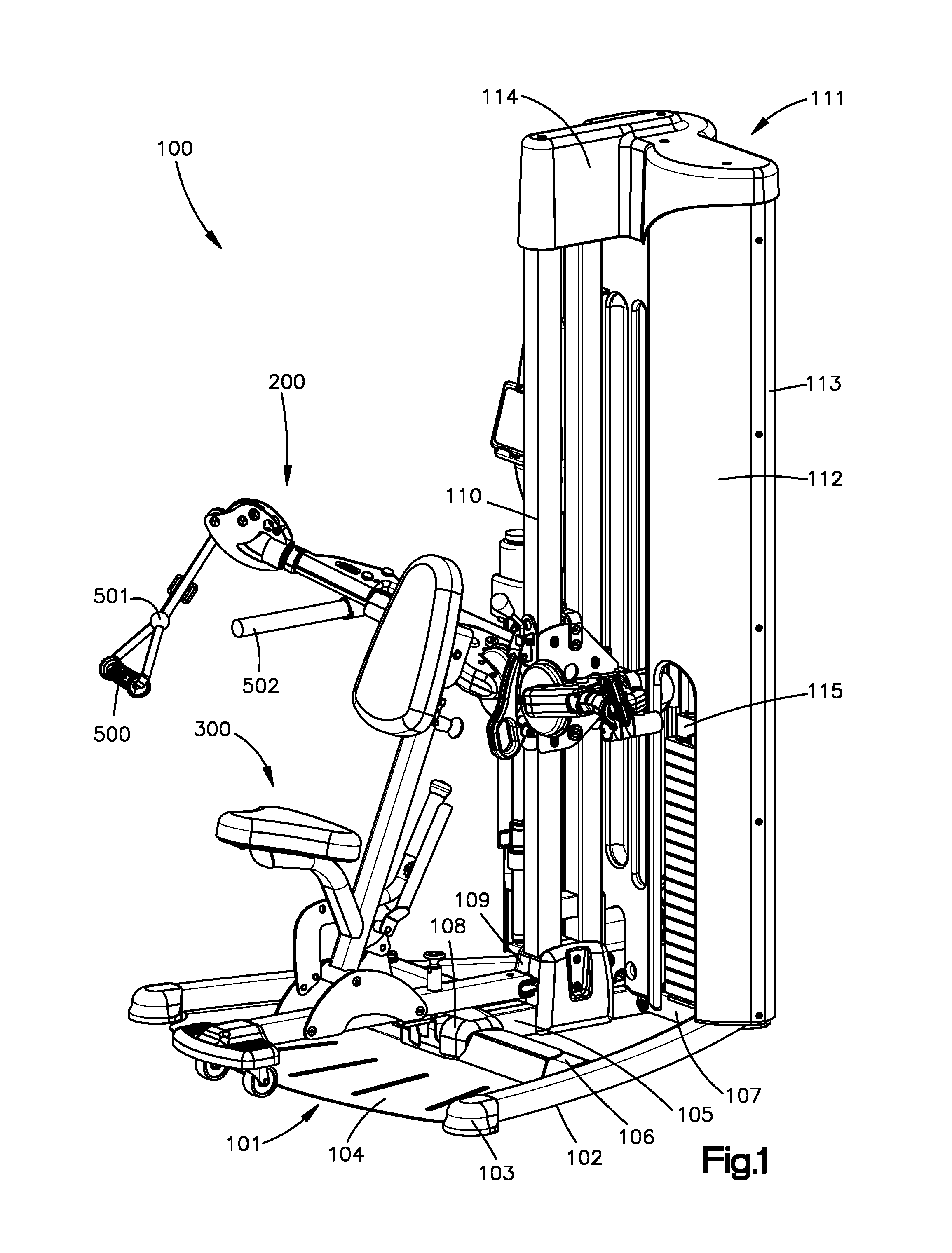
CONVERTIBLE BENCH AND UPRIGHT STABILIZING SUPPORT
This application claims the benefit of U.S. Provisional Application No. 62/211,346, filed on Aug. 28, 2015, which is incorporated herein by reference in its entirety for all purposes. This application is not the subject of any federally sponsored research or development. There have been no joint research agreements entered into with any third parties. The following description generally relates to fitness equipment. Specifically, the embodiments of the present invention are directed to an exercise machine that includes a workout bench for supporting a user. The workout bench may support a user in a seated position, or support a user's back, chest, thigh, or other body member as the user performs different exercise routines in other positions. An exercise machine may include multiple stations for performing different exercise routines in different positions. For example, an exercise machine may include a stationary bench for supporting a user while performing exercise routines in a seated position. Another station may include a stabilizing support for supporting a user while performing an exercise routine in a standing position. A functional trainer is a class of exercise machine that has become popular in recent year because of their versatility. Specifically, functional trainers include adjustable components that allow the user to perform a wide variety of exercises in a wide variety of positions. Thanks to their ability to transform themselves into different configurations, they can mimic most of the traditional multi-station machines and free weights with just a few adjustments. There are many types of functional trainers on the market today, and they use several different methods for adjusting their components. Most of them use adjustable arms, sliding carriages with pulleys or multiple pulleys mounted at different locations on the machine. Some of them can be used with a workout bench. The number of exercises that can be performed on particular machine depends on how many different configurations it can be transformed into. More configurations provide more exercise options for the user. There is a large demand for functional trainers—both in commercial and home gyms—because they can be adapted for use in a wide variety of exercises while taking up relatively little space when compared to traditional exercise machines and free weights. Accordingly, a need exists for a versatile exercise machine, such as a functional trainer, that includes a bench that can be adapted to support a user in a sitting position and that can also be adapted to serve as a stabilizing support. The embodiments of the present invention solve this problem by providing an exercise machine that includes a convertible bench adaptable to support a user performing exercises in a sitting position and adaptable to provide a stabilizing support for a user performing exercises in a non-sitting position, including in a standing position. Other advantages of the present invention will become apparent to one skilled in the art. This Summary is provided to introduce a selection of concepts in a simplified form that are further described below in the Detailed Description. This Summary is not intended to identify key features or essential features of the subject matter, nor is it intended to be used as an aid in determining the scope of the subject matter. In one aspect, an exercise machine includes a swing-away workout station and rotating arm assemblies. The swing-away workout station may be adjustable from an in-use position at the front of the exercise machine to a stowed-away position at the side of the exercise machine. The rotating arm assemblies may be movable vertically with respect to a vertical center post of the exercise machine. In another aspect, a swing-away workout station may be used with an exercise machine and may be adjustable from an in-use position at the front of the exercise machine to a stowed-away position at the side of the exercise machine. The swing-away workout station may include a bench seat and a stabilizing support that are pivotable forwardly and backwardly. The bench seat is capable of supporting the weight of a user performing exercises in a seated position. The stabilizing support is capable of providing a stabilizing support for a user performing exercises in a non-seated position. The stabilizing support may extend upwardly and downwardly to provide stabilizing support for various portions of a user's body while the user is performing different exercise routines. The foregoing summary, as well as the following detailed description, will be better understood when read in conjunction with the appended drawings. For the purpose of illustration, certain embodiments of the present invention are shown in the drawings. It should be understood, however, that the invention is not limited to the precise arrangements and embodiments shown. The accompanying drawings, which are incorporated in and constitute a part of this specification, illustrate an implementation of systems, apparatuses, and methods consistent with the present description and, together with the description, serve to explain advantages and principles consistent with the invention. Throughout the drawings and the detailed description, unless otherwise described, the same drawing reference numerals will be understood to refer to the same elements, features, and structures. The relative size and depiction of these elements may be exaggerated for clarity, illustration, and convenience. The embodiments of the present invention will now be described more fully with reference to the accompanying drawings, in which preferred embodiments of the invention are shown. The following detailed description is provided to assist the reader in gaining a comprehensive understanding of the methods, apparatuses, and/or systems described herein. This invention may, however, be embodied in many different forms and should not be construed as limited to the illustrated embodiments set forth herein. Accordingly, various changes, modifications, and equivalents of the systems, apparatuses and/or methods described herein will be suggested to or understood by those of ordinary skill in the art. Also, descriptions of well-known functions and constructions may be omitted for increased clarity and conciseness. In the following description, like reference characters designate like or corresponding parts throughout the figures. It is to be understood that the phraseology and terminology used in the following description are used for the purpose of description and enablement, and should not be regarded as limiting. Additionally, in the following description, it is understood that terms such as “top,” “bottom,” “side,” “front,” “back,” “inner,” “outer,” and the like, are words of convenience and are not to be construed as limiting terms. The base assembly 101 may include two horizontal side struts 102 on opposite sides of the exercise machine 100. Each of the horizontal side struts 102 forms a supporting structure for the exercise machine 100 and is supported by a support foot 103 on each end thereof. A central reinforcement strut 105 further supports the exercise machine 100 by extending in a direction substantially parallel to the two horizontal side struts 102 and between each of the horizontal side struts 102 at a central position. The horizontal side struts 102 and the central reinforcement strut 105 are connected by two cross struts 106, 107. A front cross strut 106 connects the two horizontal side struts 102 with the front end of the central reinforcement strut 105, and a rear cross strut 107 connects the two horizontal side struts 102 with the rear end of the central reinforcement strut 105. In this example, a base plate 104 is included on the floor surface and secured by opposite upper portions of the front cross strut 106. The base plate 104 may extend forwardly and between the two horizontal side struts 102. In this example, a strut cover 108 is used to cover the front end of the central reinforcement strut 105 and the front cross strut 106 at the position where the central reinforcement strut 105 and the front cross strut 106 are attached. A central base 109 extends vertically upwards from a position in the middle of the central reinforcement strut 105 for supporting a vertical center post 110. The vertical center post 110 supports the rotating arm assemblies 200 which move up and down to different positions along the vertical center post 110. The movement of the rotating arm assemblies 200 with respect to the vertical center post 110 will be described in more detail below in reference to A weight stack housing 111 is used for housing a weight stack assembly 115 at the rear of the exercise machine 100. The weight stack housing 111 includes a front cover 112, a rear cover 113, and a top cover 114. The front cover 112 and the rear cover 113 are attached to one another with the front cover 112 having an opening for allowing a user to access and adjust the weight stack assembly 115. The top cover 114 covers the top of the front cover 112 and the rear cover 113, and also covers the top of the vertical center post 110 for attaching the weight stack housing 111 to the vertical center post 110. Referring to Referring still to A locking pin 306 attached to the exterior post 303 may be used for locking the position of the interior post 304 with respect to the exterior post 303. The interior post 304 includes a number of alignment holes for receiving the locking pin 306 of the exterior post 303. Thus, by selectively engaging one or more of the alignment holes of the interior post 304 with the locking pin 306 of the exterior post 303, the interior post 304 and exterior post 303 may be locked together such that the interior post 304 cannot be slid longitudinally in relation to the exterior post 303. Accordingly, the position of the stabilizing support 302 may be adjusted by pulling the locking pin 306 to retract the locking pin 306 from one or more alignment holes of the interior post 304. The interior post 304 (along with the attached stabilizing support 302) may then be slid longitudinally with respect to the exterior post 303, and then once the stabilizing support 302 is in the desired position, the locking pin 306 may be released for selectively engaging with another one or more alignment holes of the interior post 304. A spring mechanism (not shown) may bias the locking pin 306 towards the alignment holes of the interior post 304, such that a user pulls the locking pin 306 to retract it from the alignment holes in order to allow for adjustment. Then, once the stabilizing support 302 is in the desired position, the user simply releases the locking pin 306 into the selected one or more alignment holes in order to lock the exterior post 303 and interior post 304 together. The workout station 300 includes a base strut 308 for movably attaching the workout station 300 to the exercise machine 100. The exterior post 303 is pivotally connected to the base strut 308. More specifically, two mounting brackets 311 are attached to opposite sides of the base strut 308. The exterior post 303 includes a pivot sleeve at the end opposite the stabilizing support 302, which is pivotally mounted between the mounting brackets 311. A pivot pin 320 passes through both mounting brackets 311 and the pivot sleeve of the exterior post 303, thus pivotally mounting the exterior post 303 on the base strut 308. As a result, the user-support portion of the workout station 300 (i.e., the stabilizing support 302, bench seat 301, exterior post 303, interior post 302, and seat post 307) are all pivotably connected to the base strut 308 and rotatable about a pivot axis that is coincident with the longitudinal axis of the pivot pin 320. As discussed above, the two mounting brackets 311 are attached to opposite sides of the base strut 308. The mounting brackets 311 further secure pivot adjustment mechanism 310 to the base strut 308. The pivot adjustment mechanism 310 provides for selectively adjustable pivoting of the user-support portion of the workout station 300 (i.e., the stabilizing support 302, bench seat 301, exterior post 303, interior post 302, and seat post 307), and will be described in more detail below in reference to Referring to The workout station 300 may be locked and unlocked from its initial position at the front of the exercise machine using a locking pin 312. The locking pin 312 is similar to the locking pin 306 described in connection with the adjustable stabilizing support 302, and may be inserted into and retracted from a hole 315 in the strut cover 108. The locking pin 312 may be spring-biased towards hole 315, such that a user pulls the locking pin 312 to retract it from hole 315 in order to allow for movement of the workout station 300 away from the front of the exercise machine 100 ( The hole 315 and strut cover 108 are configured such that, as the workout station 300 is moved away from the front of the exercise machine 100 ( Conversely, the front surface of the strut cover 108 may include a ramped surface such that, as the workout station 300 is moved into position at the front of the exercise machine 100 ( Additionally, the rear portion of the base strut 308 may be received by a front extension 316 of the central base 109 when the workout station 300 is moved into position at the front of the exercise machine 100 ( Referring to Referring to As illustrated in It should be appreciated that the examples illustrated in Further, the size of the exterior post 303 and the interior post 304 can vary such that the interior post 304 and the attached stabilizing support 302 can reach a number of different positions. In an example, when the exterior post 303 is at a 90 degree angle with respect to the horizontal, the interior post 304 may be extended such that the bottom end of the stabilizing support 302 is four meters above the base plate 104 of the exercise machine 100. In another example, the interior post 304 may be extended such that the bottom end of the stabilizing support 302 is three meters above the base plate 104. Further, the present invention is not limited as to which of the telescoping posts 303, 304 are “external” and “internal.” That is, it will be obvious to one of ordinary skill in the art that in alternative embodiments, the interior post 304 depicted in Referring to As one of ordinary skill in the art will readily appreciate, certain minimum clearance distances are necessary between various components, including, for instance, the arm assemblies 200, vertical center post 110, locking pin 214, and locking pin holes 215. These clearances are necessary to avoid interference fits, i.e., to allow easy movement of the components in light of manufacturing tolerances for the various components. However, it is desirable that these clearances not create any play, looseness, or perceived instability between the exercise machine 100 and its arm assemblies 200. Accordingly, once the arm assemblies 200 are in the desired position, the user may optionally rotate mounting bracket clamping lever 208, which exerts a clamping force on the mounting bracket 202 and vertical center post 110 to eliminate any play or looseness and to further immobilize the arm assemblies 200 with respect to the exercise machine 100. Still referring to Referring back to One of skill in the art will recognize that the examples described above are not limited to any particular size, and the size of the exercise machine will depend upon the particular application and intended components. It will be appreciated by those skilled in the art that changes could be made to the examples described above without departing from the broad inventive concept thereof. It is understood, therefore, that the invention disclosed herein is not limited to the particular examples disclosed, and is intended to cover modifications within the spirit and scope of the present invention. An exercise machine for performing a variety of different exercise routines includes a rotating arm assembly and a swing-away workout station. The workout station may include a bench seat and a stabilizing support, and may be adjusted to provide for a number of different configurations. For example, the bench seat and the stabilizing support may pivot forward and backward, and the stabilizing support may extend upward and downward for supporting the user's body in different positions, while performing different exercise routines. 1. An exercise machine for performing exercise routines in different positions, comprising:
an arm assembly; and a swing-away workout station, comprising
a bench; a pivot pin; and a locking mechanism, wherein the swing-away workout station is configured to be locked to a first position at a front of the exercise machine using the locking mechanism and stowed away from the first position to a second position at a side of the exercise machine using the pivot pin. 2. The exercise machine of a base assembly comprising a pair of horizontal cross struts, and a front cross strut extending between the pair of horizontal cross struts and comprising a strut cover, wherein the locking mechanism is configured to lock to the strut cover. 3. The exercise machine of wherein the base assembly further comprises a central base supporting the arm assembly and comprising a front extension, and the swing-away workout station comprises a base strut supporting the bench and configured to engage the central base in response to the swing-away workout station being in the first position. 4. The exercise machine of a vertical center post extending upright from the base assembly, wherein the arm assembly is adjustably secured to the vertical center post and configured to be displaced to different portions of the vertical center post. 5. The exercise machine of a base strut; a bench post supporting the bench; and a pivot adjustment mechanism connecting the bench post to the base strut for pivoting the bench between different positions. 6. The exercise machine of 7. The exercise machine of 8. The exercise machine of a pair of mounting brackets; a pivot adjustment plate comprising holes; a locking pin; a pivot adjustment handle; and a locking pin handle, and wherein the another pivot pin is attached to a distal end of the bench post and between the pair of mounting brackets for rotatably attaching the bench post to the pair of mounting brackets, the pivot adjustment plate is attached between the pair of mounting bracket, and the pivot adjustment handle and the locking pin handle are attached to the bench post, and the locking pin handle is configured to retract the locking pin from the holes of the pivot adjustment plate for pivoting the bench post and the bench with respect to the exercise machine. 9. The exercise machine of a pair of rotating arms; an arm mounting bracket; a vertical adjustment lever for adjusting a position of the arm assembly and arm mounting bracket with respect to the exercise machine; and a pair of rotation adjustment levers configured to rotate each of the pair of rotating arms with respect to the arm mounting bracket. 10. An exercise machine for performing exercise routines in different positions, comprising:
a base assembly; an arm assembly; and a workout station, comprising:
a base strut; a bench; a bench post supporting the bench; and a pivot adjustment mechanism connecting the bench post to the base strut for pivoting the bench between different positions, the pivot mechanism comprising:
a pivot pin; a pair of mounting brackets; a pivot adjustment plate comprising holes; a locking pin; a pivot adjustment handle; and a locking pin handle, wherein the pivot pin is attached to an end of the bench post and between the pair of mounting brackets for rotatably attaching the bench post to the pair of mounting brackets, the pivot adjustment plate is attached between the pair of mounting bracket, and the pivot adjustment handle and the locking pin handle are attached to the bench post, and the locking pin handle is configured to retract the locking pin from the holes of the pivot adjustment plate for pivoting the bench post and the bench with respect to the exercise machine. 11. The exercise machine of a vertical center post extending upright from the base assembly, wherein the arm assembly is adjustably secured to the vertical center post and configured to be displaced to different portions of the vertical center post. 12. The exercise machine of 13. The exercise machine of 14. The exercise machine of a pair of rotating arms; an arm mounting bracket; a vertical adjustment lever for adjusting a position of the arm assembly and arm mounting bracket with respect to the exercise machine; and a pair of rotation adjustment levers configured to rotate each of the pair of rotating arms with respect to the arm mounting bracket. 15. The exercise machine of 16. A method of using an exercise machine for performing exercise routines in different positions, comprising:
providing an exercise machine, comprising
a base assembly; and a swing-away workout station, comprising
a bench; a pivot pin; and a locking mechanism, moving the swing-away workout station to a first position at a front of the exercise machine from a second position at a side of the exercise machine using the pivot pin; and locking the swing-away workout station to the first position at the front of the exercise machine using the locking mechanism. 17. The method of 18. The method of unlocking the swing-away workout station using the locking mechanism; and moving the swing-away workout station from the first position to the second position. 19. The method of CROSS-REFERENCE TO RELATED APPLICATIONS
STATEMENT REGARDING FEDERALLY SPONSORED RESEARCH OR DEVELOPMENT
THE NAMES OF THE PARTIES TO A JOINT RESEARCH AGREEMENT
FIELD OF THE INVENTION
BACKGROUND OF THE INVENTION
SUMMARY OF THE INVENTION
BRIEF DESCRIPTION OF THE DRAWINGS
DETAILED DESCRIPTION
100-exercise machine 101-base assembly 102-horizontal side strut 103-support foot 104-base plate 105-central reinforcement strut 106-front cross strut 107-rear cross strut 108-strut cover 109-central base 110-vertical center post 111-weight stack housing 112-front cover 113-rear cover 114-top cover 115-weight stack assembly 200-rotating arm assembly 201-arm 202-arm mounting bracket 203-bar receiving member 204-pulley housing 205-gripping region 206-rotation adjustment lever 207-vertical adjustment lever 208-mounting bracket clamping lever 209-arm reinforcement 210-horizontal linkage 213-vertical linkage 214-locking pin 215-locking pin holes 220-rotation adjustment plate 221-locking pin holes 222-spring-biased locking pin 300-swing-away workout station 301-bench seat 302-stabilizing support 303-exterior bench post 304-interior bench post 305-support bracket 306-locking pin 307-seat post 308-base strut 309-wheel assembly 310-pivot adjustment mechanism 311-mounting bracket 312-locking pin 313-pivot pin 314-side strut 315-strut cover hole 316-front extension 320-pivot pin 321-pivot adjustment plate 322-pivot adjustment plate holes 323-locking pin 324-locking pin handle 325-pivot adjustment handle 326-handle hinge 327-locking pin plate 328-rear post extension 329-spring 500-handle unit 501-stopper 502-chin-up and dip bar assembly 600-storage and holder unit 601-device holder 602-bottle holder 603-storage compartment 3110-first hole of mounting bracket 3120-second hole of mounting bracket 3130-third hole of mounting bracket 3140-fourth hole of mounting bracket 3150-fifth hole of mounting bracket 3160-sixth hole of mounting bracket 3210-first hole of adjustment plate 3220-second hole of adjustment plate 3230-third hole of adjustment plate
The list of reference numerals is provided for convenience and is intended to aid understanding of the illustrated examples described above. The examples of the present invention may be described in many different forms and should not be construed as limited to the illustrated examples. Likewise, the list above setting forth the reference numerals and associated components comprising the illustrated examples do not limit the scope of the invention.