LIQUID COOLED RACK INFORMATION HANDLING SYSTEM HAVING STORAGE DRIVE CARRIER FOR LEAK CONTAINMENT AND VIBRATION MITIGATION
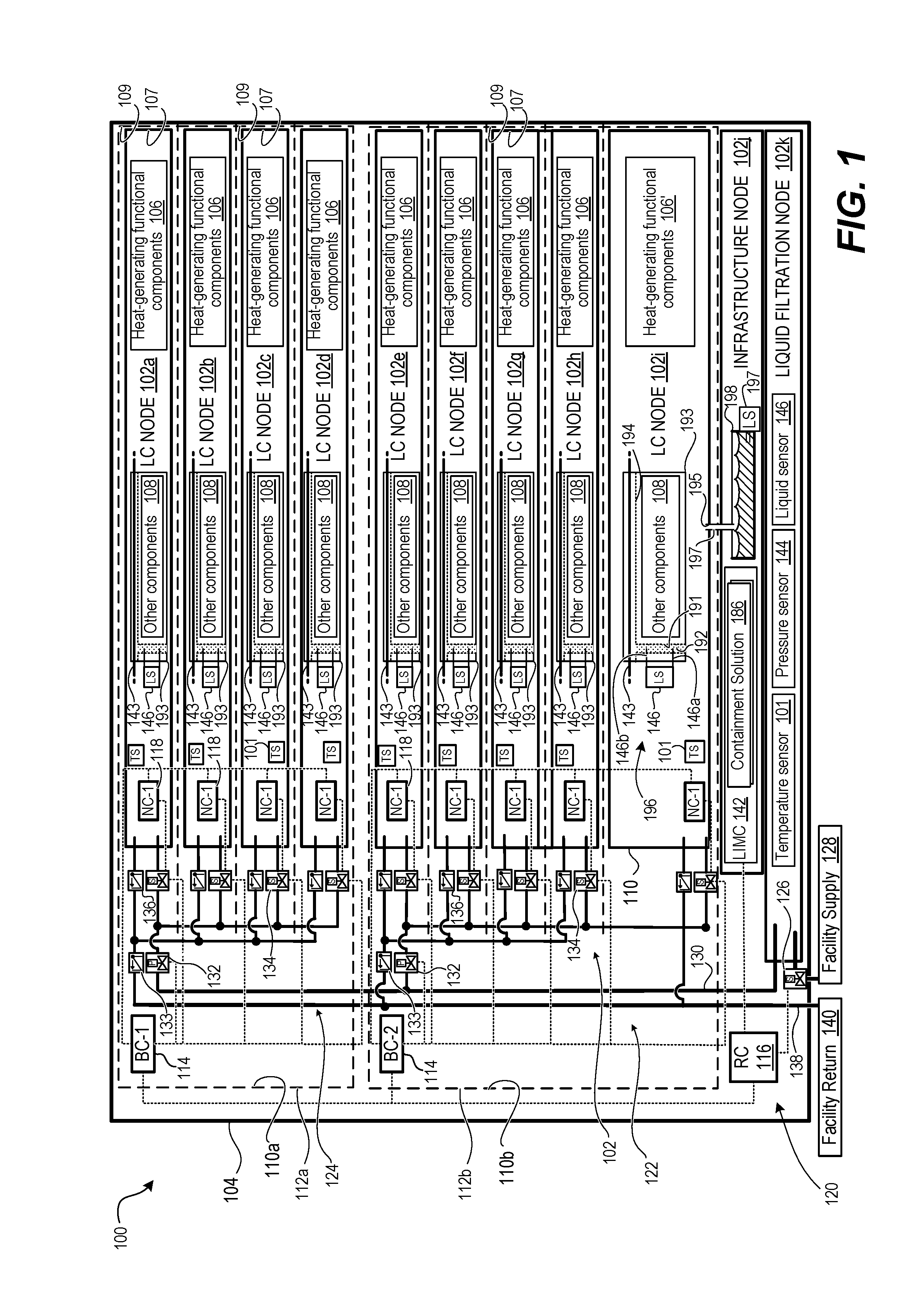
The present invention claims priority from each of the following provisional patent applications, with relevant content of each listed provisional application incorporated herein by reference: Provisional Application Ser. No. 62/270,563, Docket No. 106280.02, with filing date Dec. 21, 2015; and Provisional Application Ser. No. 62/270,575 Docket No. 106285.02, with filing date Dec. 21, 2015. 1. Technical Field The present disclosure generally relates to information handling systems (IHS), and more particular to a direct-interface liquid cooled (DL) rack-configured HIS (RIHS), having a liquid cooling subsystem and liquid-cooled nodes. Still more particularly, the disclosure is related to mitigating risk to computing components from cooling liquid leaks within the RIHS. 2. Description of the Related Art As the value and use of information continue to increase, individuals and businesses seek additional ways to process and store information. One option available to users is Information Handling Systems (IHSs). An IHS generally processes, compiles, stores, and/or communicates information or data for business, personal, or other purposes, thereby allowing users to take advantage of the value of the information. Because technology and information handling needs and requirements vary between different users or applications, IHSs may also vary regarding what information is handled, how the information is handled, how much information is processed, stored, or communicated, and how quickly and efficiently the information may be processed, stored, or communicated. The variations in IHSs allow for IHSs to be general or configured for a specific user or specific use such as financial transaction processing, airline reservations, enterprise data storage, or global communications. In addition, IHSs may include a variety of hardware and software components that may be configured to process, store, and communicate information and may include one or more computer systems, data storage systems, and networking systems. For implementations requiring a large amount of processing capability, a rack-configured (or rack) IHS (RIHS) can be provided. The RIHS includes a physical rack, within which is inserted a plurality of functional nodes, such as server (or processing) nodes/modules, storage nodes, and power supply nodes. These nodes, and particularly the server nodes, typically include processors and other functional components that dissipate heat when operating and/or when connected to a power supply. Efficient removal of the heat being generated by these components is required to maintain the operational integrity of the RIHS. Traditional heat removal systems include use of air movers, such as fans, to convectionally transfer the heat from inside of the RIHS to outside the RIHS. More recently, some RIHS have been designed to enable submersion of the server modules and/or the heat generating components in a tank of cooling liquid to effect cooling via absorption of the heat by the surrounding immersion liquid. The amount of processing capacity and storage capacity per node and/or per rack continues to increase, providing greater heat dissipation per node and requiring more directed cooling solutions. Thus, there is a continuing need for further innovations to provide directed cooling for the individual heat generating components, both at the individual node level, as well as at the larger rack level. When designing the cooling subsystem, consideration must also be given to the different form factors of IT nodes and rack heights of the RIHS, and the ability to effectively control cooling discretely (at device or node level) and generally across the overall RIHS. As liquid cooling improves in efficiencies and performance, data center solutions continue to focus on implementing liquid cooling at the rack level. Recently, localized liquid solutions (CPU/GPU cold plates) have been successful in removing most of the heat from these components within a server and into the facility cooling loop through direct fluid-to-fluid heat exchangers (server cooling loop to facility cooling loop) within the rack. However, when liquid is introduced into an electronic enclosure, there is potential for leaks, which can cause catastrophic system failure. Within the system enclosure, locations exist where an electronic short will create an exothermal reaction that can cause permanent damage to the system. The illustrative embodiments of the present disclosure provides a Direct-Interface Liquid-Cooled (DL) Rack Information Handling System (RIHS), a direct-interface liquid cooling subsystem, and a method for modularly providing liquid cooling to information technology (IT) nodes within a RIHS, where the nodes are liquid cooled (LC) nodes that contain heat-generating functional components that require protection from any liquid that leaks from DL subsystem. According to one aspect, a DL RIHS includes a rack having chassis-receiving bays. The DL RIHS includes at least one LC node having a chassis received in a respective chassis-receiving bay of the rack. The chassis contains heat-generating functional components. The LC node is configured with a system of conduits to receive direct injection of cooling liquid to regulate the ambient temperature of the node. The direct injection provides cooling to the functional components inside the node by removing heat generated by the heat-generating functional components. The chassis includes a leak containment barrier configured with a trough that underlays a portion of the system of conduits of the LC node. The trough forms a drain path to a drain port of the chassis. In one or more embodiments, the storage drive carrier comprises vibration absorbing material that mitigates vibrations of a storage drive placed in the storage drive carrier. According to one aspect, an LC node of an RIHS includes a chassis configured to be received in chassis-receiving bay of a rack. At least one heat-generating functional component that generates heat internal to the chassis requires cooling. A system of conduits has an inlet port and an outlet port for connecting to a cooling liquid supply to receive direct intake/flow of cooling liquid. The cooling liquid regulates the ambient temperature of the LC node by absorbing and transferring heat from within the node via the cooling liquid. A leak containment barrier is configured with a trough that underlays a portion of the system of conduits of the LC node. The trough forms a drain path to a drain port of the chassis. According to one aspect, the present disclosure provides a method of assembling a DL RIHS. In one or more embodiments, the method includes inserting a leak containment barrier in a node enclosure. The method includes provisioning the node enclosure with heat-generating functional components. The method includes attaching the system of conduits supplying cooling liquid through the node enclosure. The system of conduits includes a supply conduit extending from the node inlet coupling and a return conduit terminating in the node outlet coupling. A trough of the leak containment barrier underlays a portion of the system of conduits of the LC node and forms a drain path to a drain port of the node enclosure. The method includes mounting the LC node insertably received in the one node-receiving slot of a rack having one or more node-receiving slots. Each slot has a front opening for node insertion and a rear section opposed to the front access. For blind mating of the node inlet and outlet ports, a node-receiving liquid inlet port and a node-receiving liquid outlet port are located at the rear section of one node-receiving slot. The node-receiving liquid inlet and outlet ports are positioned to be inwardly facing to the LC node inserted in the one node-receiving slot. According to one aspect, the present disclosure provides a method of containing leaks in a DL RIHS. In one or more embodiments, the method includes a controller communicating with a liquid sensor to detect liquid received in a leak containment barrier. The detected liquid is leaked in a trough from a received system of conduits internal to a node enclosure of a LC node that is provisioned with a heat-generating computing component. The method includes interrupting the supply flow of cooling liquid to the LC node by causing a shutoff valve to close. The above presents a general summary of several aspects of the disclosure in order to provide a basic understanding of at least some aspects of the disclosure. The above summary contains simplifications, generalizations and omissions of detail and is not intended as a comprehensive description of the claimed subject matter but, rather, is intended to provide a brief overview of some of the functionality associated therewith. The summary is not intended to delineate the scope of the claims, and the summary merely presents some concepts of the disclosure in a general form as a prelude to the more detailed description that follows. Other systems, methods, functionality, features and advantages of the claimed subject matter will be or will become apparent to one with skill in the art upon examination of the following figures and detailed written description. The description of the illustrative embodiments can be read in conjunction with the accompanying figures. It will be appreciated that for simplicity and clarity of illustration, elements illustrated in the figures have not necessarily been drawn to scale. For example, the dimensions of some of the elements are exaggerated relative to other elements. Embodiments incorporating teachings of the present disclosure are shown and described with respect to the figures presented herein, in which: The present disclosure generally provides a Direct-Interface Liquid-Cooled (DL) Rack Information Handling System (RIHS) providing liquid cooled (LC) information technology (IT) nodes containing heat-generating functional components and which are cooled at least in part by a liquid cooling subsystem. The RIHS includes a rack configured with chassis-receiving bays in which is received a respective chassis of one of the LC nodes. Each LC node is configured with a system of conduits to receive direct intake/flow of cooling liquid to regulate the ambient temperature of the node. Additionally, each LC node, configured with a system of conduits, provides cooling to the components inside the node by conductively absorbing, via the cooling liquid, heat generated by the heat-generating functional components. The absorbed heat is removed (or transferred away) from within the node to outside of the node and/or the RIHS. The chassis has a leak containment barrier configured with a trough that underlays a portion of the system of conduits of the LC node and that forms a drain path to a drain port of the chassis. Based on portions of the RIHS that can be exposed to the leak, a Liquid Infrastructure Management Controller (LINC) implements a leak detection solution to avoid or mitigate damage to computing components. In the following detailed description of exemplary embodiments of the disclosure, specific exemplary embodiments in which the disclosure may be practiced are described in sufficient detail to enable those skilled in the art to practice the disclosed embodiments. For example, specific details such as specific method orders, structures, elements, and connections have been presented herein. However, it is to be understood that the specific details presented need not be utilized to practice embodiments of the present disclosure. It is also to be understood that other embodiments may be utilized and that logical, architectural, programmatic, mechanical, electrical and other changes may be made without departing from general scope of the disclosure. The following detailed description is, therefore, not to be taken in a limiting sense, and the scope of the present disclosure is defined by the appended claims and equivalents thereof. References within the specification to “one embodiment,” “an embodiment,” “embodiments”, or “one or more embodiments” are intended to indicate that a particular feature, structure, or characteristic described in connection with the embodiment is included in at least one embodiment of the present disclosure. The appearance of such phrases in various places within the specification are not necessarily all referring to the same embodiment, nor are separate or alternative embodiments mutually exclusive of other embodiments. Further, various features are described which may be exhibited by some embodiments and not by others. Similarly, various requirements are described which may be requirements for some embodiments but not other embodiments. It is understood that the use of specific component, device and/or parameter names and/or corresponding acronyms thereof, such as those of the executing utility, logic, and/or firmware described herein, are for example only and not meant to imply any limitations on the described embodiments. The embodiments may thus be described with different nomenclature and/or terminology utilized to describe the components, devices, parameters, methods and/or functions herein, without limitation. References to any specific protocol or proprietary name in describing one or more elements, features or concepts of the embodiments are provided solely as examples of one implementation, and such references do not limit the extension of the claimed embodiments to embodiments in which different element, feature, protocol, or concept names are utilized. Thus, each term utilized herein is to be given its broadest interpretation given the context in which that terms is utilized. As utilized herein, the term “rack-configured” (as in RIHS) generally refers to the configuration of a large scale sever system within a physical rack having multiple chassis receiving rails for receiving specific sizes of information technology (IT) nodes, such as server modules, storage modules, and power modules. The term node generally refers to each separate unit inserted into a 1 U or other height rack space within the rack. In one embodiment, operational characteristics of the various IT nodes can be collectively controlled by a single rack-level controller. However, in the illustrated embodiments, multiple nodes can be arranged into blocks, with each block having a separate block-level controller that is communicatively connected to the rack-level controller. For purposes of this disclosure, an information handling system (defined at the individual server level) may include any instrumentality or aggregate of instrumentalities operable to compute, classify, process, transmit, receive, retrieve, originate, switch, store, display, manifest, detect, record, reproduce, handle, or utilize any form of information, intelligence, or data for business, scientific, control, or other purposes. For example, an information handling system may be a personal computer, a network storage device, or any other suitable device and may vary in size, shape, performance, functionality, and price. The information handling system may include random access memory (RAM), one or more processing resources such as a central processing unit (CPU) or hardware or software control logic, ROM, and/or other types of nonvolatile memory. Additional components of the information handling system may include one or more disk drives, one or more network ports for communication with external devices as well as various input and output (I/O) devices, such as a keyboard, a mouse, and a video display. The information handling system may also include one or more buses operable to transmit communications between the various hardware components. As illustrated by the figures and described herein, multiple processing servers or server IHSs (referred to herein as server nodes) can be included within the single RIHS. Certain aspect of the disclosure then relate to the specific LC (sever or other) nodes and the functionality associated with these individual nodes or block-level groupings of nodes, while other aspects more generally relate to the overall DL RIHS containing all of the LC nodes. As one design detail/aspect for the present innovation, consideration is given to the fact that extreme variations can exist in server/power/network topology configurations within an IT rack. In addition to dimension variations, the thermal requirements for heat-generating functional components for power, control, storage and server nodes can be very different between types or vary according to usage. These variations drive corresponding extreme diversity in port placement, fitting size requirements, mounting locations, and manifold capacity for a liquid cooling subsystem. Further, a chassis of each node is typically densely provisioned. Lack of space thus exists to mount a discrete water distribution manifold in high-power IT racks. The present disclosure addresses and overcomes the challenges with distributing liquid cooling fluids throughout an IT rack having nodes with a large number of variations in distribution components. The disclosure also includes the additional consideration that in addition to cooling the primary heat generating components of the rack, such as the processor, what is needed is a way to allow for cooling of secondary equipment within the rack, as well as auxiliary components that would further support utilizing the advantages of a fluid-to-fluid heat exchanger methodology. Additionally, the present disclosure provides a modular approach to utilizing an air-to-liquid heat exchanger with quick connection and scalability to allow the solution to be scalable in both 1 U and 2 U increments. The present innovation is not limited to any specific number or configuration of nodes 102 or blocks 112 in a rack 104. According to one aspect, nodes 102 can be of different physical heights of form factors (e.g., 1 U, 1.5 U, 2 U), and the described features can also be applied to nodes 102 having different widths and depths (into the rack), with some extensions made and/or lateral modifications to the placement of cooling subsystem conduits, as needed to accommodate the different physical dimensions. As a specific example, node 102 A Direct-Interface Liquid Cooling (DL) subsystem (generally shown as being within the RIHS and labelled herein as 120) provides direct-intake/flow of cooling liquid to heat-generating functional components 106 via a liquid rail 124 under the control of rack-level controller 116, block-level controllers 114, and/or node-level controllers 118, in some embodiments. Rack-level controller 116 controls a supply valve 126, such as a solenoid valve, to allow cooling liquid, such as water, to be received from a facility supply 128. The cooling liquid is received from facility supply 128 and is passed through liquid filtration node 102 To support the temperature control aspects of the overall system, RIHS 100 includes temperature sensors 101 that are each located within or proximate to each node 102 DL nodes 102 The drain conduits 197 converge into a collection structure 198 that receives leaked liquid that flows through the cascading gutter structure. LIMC 142 is in communication with the at least one liquid sensor 146 that triggers a closing of one or more shutoff valve 132, 134 in response to a corresponding liquid sensor 146 detecting a liquid leak in the RIHS 100. In one or more embodiments, LIMC 142 is in communication with the node-level, block-level, and rack-level liquid sensors 146. LIMC 142 associates a leak with a containment solution 186. LIMC 142 triggers closure of one or more shutoff valves 126, 132, and 134 to effect the containment solution 186 in response to the detected presence of liquid in the collection structure. According to one aspect, support surface 294 of node-level carrier 258 incorporates a vibration absorbing material that can be integral to structural portions of the node-level carrier 258. In one or more embodiments, top vibration absorbing component 295, such as a double-sided, adhesive backed, foam strip, can provide an attachment of storage devices 262 to the node-level carrier 258. In one or more embodiments, bottom vibration absorbing component 296, such as a double-sided, adhesive backed, foam strip, can provide an attachment of node-level carrier 258 to node enclosure 207. The vibration absorbing material isolates sources of vibration to prevent the vibration from constructively amplifying to the point of impairing performance or damaging IT equipment. For example, a storage drive 262 can include a disk drive that creates a vibration during a repeated sequence of sector reads or writes. As another example, the liquid cooling system can include vibrations originating from movement/flow of the fluid moving and/or flow volume control. As yet an additional example, air movers can create vibrations. With these vibration absorbing materials integrated into the design, node-level carrier 258 protects the storage devices 262 from vibrations originating at or otherwise delivered to storage devices 262. At the top position of RIHS 800, a block chassis 810 is received in a block chassis receiving bay 870 MLD conduits 878 Each MLD conduit 878 Liquid cooling subsystem 822 includes a liquid infrastructure manager controller (LIMC) 842 which is communicatively coupled to block liquid controllers (BLCs) 887 to collectively control the amount of cooling liquid that flows through the RIHS 800 and ultimately through each of the nodes 802 in order to effect a desired amount of liquid cooling at the component level, node level, block level, and rack level. For clarity, LIMC 842 and BLCs 887 are depicted as separate components. In one or more embodiments, the liquid control features of the LIMC 842 and BLCs 887 can be incorporated into one or more of the rack-level controller 816, block-level controllers 820, and the node-level controllers 818. As illustrated in As another aspect, the present disclosure provides a modular approach to utilizing air-to-liquid heat exchanger 888 with quick connection and is scalable in both 1 U and 2 U increments. In one or more embodiments, DL cooling subsystem 822 can include a plurality of air-to-liquid (or liquid-to-air) heat exchangers 888 that facilitate the release of some of the heat absorbed by the exhaust liquid to the surrounding atmosphere around the RIHS 100 (of RIHS 800 can include variations in LC node 802 that still maintain uniformity in interconnections along liquid rail 824 formed by a chassis-to-chassis modular interconnect system of MLD conduits 878 The system of conduits extending from node intake valve 834 into each LC node 802 enables each LC node 802 to engage to block liquid manifold 889. Block chassis 810 or node enclosure 807 of each LC node 102 provides the intake and exhaust conduit connections to engage to respective terminals of MLD conduits 878 Supply and return bypass tubes 890, 891 of each block liquid manifold 889 are connected by MLD conduits 878 In an exemplary embodiment, the scalable rack manifold provided by liquid rail 824 is formed in part by MLD conduits 878 Cooling subsystem 822 can support an embedded liquid-to-liquid heat exchanger manifold 841, such as in LC node 802 Additionally, the liquid cooling subsystem 822 also includes a filtration system or unit 871, which prevents chemical impurities and particulates from clogging or otherwise damaging the conduits as the fluid passes through the network of conduits. According to one aspect of the disclosure, liquid cooling subsystem 822 provides RFU 871 in fluid connection with the intake pipes from facility supply 828. In at least one embodiment, RFU 871 includes a sequenced arrangement of liquid filters within a full-sized sled that can be removably inserted by an end user into one of the receiving slots of rack 804. In one embodiment, the RFU 871 is located on an infrastructure sled having rack-level controllers and other rack-level functional components. In at least one embodiment, the entirety of the sled is filed with components associated with RFU 871. Thus, it is appreciated that the RFU 871 may occupy the entire area of one vertical slot/position within the chassis. Alternate locations of the RFU 871 can also be provided, in different embodiments, with an ideal location presenting the intake port of the RFU 871 in close proximity to a connection to facility supply 828 to directly receive the facility supply 828 prior to the liquid being passed into the remainder of the conduits of the liquid cooling subsystem 822. It is appreciated that if the system was capable of completing all heat exchange within the rack, then sealing the rack would be feasible and would reduce and/or remove any requirements for filtration and/or allocation of rack space for RFU 871. Liquid cooled compute systems use the high heat transport capacity of water. However, the disclosure recognizes and addresses the fact that with liquid introduced into an electronic enclosure, there is a potential for leaks that can cause catastrophic system failure. Also, in some instances, a leak can create an electronic short with a resulting exothermal reaction causing permanent damage to the DL RIHS 800. To mitigate such risks, as one design feature, node-level HDD carrier or leak containment barrier 893 can include a trench/gutter system or trough 894. In one embodiment, the gutter system can also incorporate an absorbent material that can accumulate sufficient amounts of liquid from small leaks to enable external sensing of the leak. Advantageously, the leak containment barrier 893 can also be thermally conductive to serve as a heat sink for components such as storage devices 808. In one embodiment, another leak detection solution that can be incorporated into the LC node 802 involves use of a solenoid to create an event when additional current is applied, due to water pooling around the solenoid. Barriers on leak containment barrier 893 can be specifically designed to contain a liquid leak and assist in funneling the liquid through the gutter system. Liquid rail 824 can also be provided with leak containment and detection. In one or more embodiments, removable pipe covers 876 are sized to be mounted around respective MLD conduits 878 In one or more embodiments, DL RIHS 800 further incorporates a node-level liquid containment structure 803 with a cascading drain runoff tubing network 896 to a rack-level cascading liquid containment structure 895. In one or more embodiments, the DL RIHS 800 further incorporates leak detection command such as partial or complete automated emergency shutdown. Liquid sensors (LS) 897 at various cascade levels can identify affected portions of DL RIHS 800. Containment and automatic shutoff can address the risks associated with a leak developing in the DL cooling system 822. The cooling subsystem 920 includes block liquid manifolds 989 mountable at a back side of the rack 904. Each block liquid manifold has at least one rail supply port 917 and at least one rail return port 919 on an outside facing side of the block liquid manifold 989. The at least one rail supply port 917 and the at least one rail return port 919 respectively communicate with at least one block supply port 921 and a block return port 923 on an inside facing side of the block liquid manifold 989. LC nodes 902 are insertable in receiving bays 970 of rack 904 corresponding to locations of the mounted block liquid manifolds 989. Block supply ports 921 and block return ports 923 of the LC nodes 902 and an inside facing portion of the corresponding block liquid manifold 989 are linearly aligned. The linear alignment enables direct sealing, for fluid transfer, of the lineally aligned inside manifold supply ports 925 and return ports 927 to the inside facing portion of the block liquid manifold 989. In one or more embodiments, block supply port 921 sealed to the internal manifold supply port 925 communicates via supply bypass tube 990 to two rail supply ports 917. Block return port 923 sealed to internal manifold return port 927 communicates via return bypass tube 991 of the respective block liquid manifold 989 to two rail return ports 919. Fan modules 982 mounted respectively onto back of block liquid manifold 989 have apertures to expose rail supply and return ports 917, 919. Additionally, fan modules 982 draw hot air 999 from LC nodes 902 through an air-liquid heat exchanger 988 in block liquid manifold 989. In one or more embodiments, supply liquid conduit 992 In one or more embodiments, RIHS 900 can provide hot-pluggable server-level liquid cooling, an integrated leak collection and detection trough, and an automatic emergency shut-off circuit. At a block level, RIHS 900 can provide embedded air-to-liquid heat exchange, and dynamic liquid flow control. At a rack level, RIHS 900 can provide facility-direct coolant delivery, a scalable rack fluid network, a rack filtration unit, and automated rack flow balancing, and a service mode. According to one embodiment, liquid rail 924 includes a series of secondary conduits, such as a supply divert conduit 997 and a return divert conduit 998, that provides a by-pass fluid path for each of MLD conduits 978. In operation, divert conduit 997 allows for the removal of corresponding MLD conduit 978, thus removing the flow of cooling liquid to the particular block of nodes, without interrupting the flow of cooling liquid to the other surrounding blocks of computer gear. For example, a particular MLD conduit 978 can be replaced due to a leak. For another example, a block liquid manifold 989 can be replaced. The inclusion of divert conduits 997, 998 thus enables rapid servicing and maintenance of block liquid manifold 989 and/or nodes within block chassis without having to reconfigure the MLD conduits 978. In addition, the RIHS 900 can continue operating as cooling liquid continues to be provided to the remainder of the blocks that are plugged into the liquid rail. Re-insertion of the MLD conduit 978 then reconnects the flow of cooling liquid to the block for normal cooling operations, and shuts off the diverted flow of cooling liquid. In an exemplary embodiment, the MLD conduits 978 provide a quick disconnect feature that interrupts flow when not fully engaged to a respective port 917, 919, 921, 923. Disconnection of an MLD conduit 978 interrupts flow in a primary portion of the liquid rail 924 for either supply or return, shifting flow through one or more divert conduits 997 to provide cooling liquid to the other block liquid manifolds 989. In one or more embodiments, a manual or active shutoff valve can interrupt flow on either or both of the primary or divert portions of the liquid rail 924. In one or more embodiments, each LC node 902 can receive liquid cooling service from a corresponding block liquid manifold 928 as illustrated by In an exemplary embodiment, the method 1000 can include receiving node (server), block and rack-level sensor signals as listed in Table 1200 in In the above described flow charts of One or more of the embodiments of the disclosure described can be implementable, at least in part, using a software-controlled programmable processing device, such as a microprocessor, digital signal processor or other processing device, data processing apparatus or system. Thus, it is appreciated that a computer program for configuring a programmable device, apparatus or system to implement the foregoing described methods is envisaged as an aspect of the present disclosure. The computer program may be embodied as source code or undergo compilation for implementation on a processing device, apparatus, or system. Suitably, the computer program is stored on a carrier device in machine or device readable form, for example in solid-state memory, magnetic memory such as disk or tape, optically or magneto-optically readable memory such as compact disk or digital versatile disk, flash memory, etc. The processing device, apparatus or system utilizes the program or a part thereof to configure the processing device, apparatus, or system for operation. While the disclosure has been described with reference to exemplary embodiments, it will be understood by those skilled in the art that various changes may be made and equivalents may be substituted for elements thereof without departing from the scope of the disclosure. In addition, many modifications may be made to adapt a particular system, device or component thereof to the teachings of the disclosure without departing from the essential scope thereof. Therefore, it is intended that the disclosure not be limited to the particular embodiments disclosed for carrying out this disclosure, but that the disclosure will include all embodiments falling within the scope of the appended claims. Moreover, the use of the terms first, second, etc. do not denote any order or importance, but rather the terms first, second, etc. are used to distinguish one element from another. The terminology used herein is for the purpose of describing particular embodiments only and is not intended to be limiting of the disclosure. As used herein, the singular forms “a”, “an” and “the” are intended to include the plural forms as well, unless the context clearly indicates otherwise. It will be further understood that the terms “comprises” and/or “comprising,” when used in this specification, specify the presence of stated features, integers, steps, operations, elements, and/or components, but do not preclude the presence or addition of one or more other features, integers, steps, operations, elements, components, and/or groups thereof. The description of the present disclosure has been presented for purposes of illustration and description, but is not intended to be exhaustive or limited to the disclosure in the form disclosed. Many modifications and variations will be apparent to those of ordinary skill in the art without departing from the scope of the disclosure. The described embodiments were chosen and described in order to best explain the principles of the disclosure and the practical application, and to enable others of ordinary skill in the art to understand the disclosure for various embodiments with various modifications as are suited to the particular use contemplated. A direct-contact liquid-cooled (DL) Rack Information Handling System (RIHS) includes liquid cooled (LC) nodes having a chassis received in a respective chassis-receiving bay of the rack and containing heat-generating functional components. The LC node configured with a system of conduits to receive direct contact of cooling liquid to regulate the ambient temperature of the node and provide cooling to the functional components inside the node by removing heat generated by the heat-generating functional components. The chassis has a leak containment barrier configured with a trough that underlays a portion of the system of conduits of the LC node and that forms a drain path to a drain port of the chassis. In one or more embodiments, the storage drive carrier has vibration absorbing material that mitigates vibrations of a storage drive placed in the storage drive carrier. 1. A Rack Information Handling System (RIHS) comprising:
a rack having chassis-receiving bays; and at least one liquid cooled (LC) node comprising a chassis received in a respective chassis-receiving bay of the rack and containing heat-generating functional components, the LC node configured with a system of conduits to receive direct intake/flow of cooling liquid to regulate the ambient temperature of the node and provide cooling to the functional components inside the node by removing heat generated by the heat-generating functional components; wherein the chassis comprises a leak containment barrier configured with a trough that underlays a portion of the system of conduits of the LC node and that forms a drain path to a drain port of the chassis. 2. The RIHS of 3. The RIHS of at least one shutoff valve to interrupt the supply flow of cooling liquid to at least a selected LC node; at least one liquid sensor that detects liquid leaks from the DL subsystem and LC nodes; and a liquid infrastructure manager controller (LIMC) in communication with the at least one sensor that triggers a closing of one or more of the at least one shutoff valve in response to a corresponding liquid sensor detecting a liquid leak in the RIHS. 4. The RIHS of more than one block liquid manifold mounted to the rack in alignment with respective chassis-receiving bays, each block liquid manifold comprising manifold supply and return bypass tubes that terminate in a pair respectively of rail supply ports and rail return ports and that each communicate with the system of conduits of a corresponding at least one LC node; and a liquid rail formed by more than one Modular Liquid Distribution (MLD) conduit connecting for fluid transfer respectively rail supply and return ports of adjacent LC nodes into a rail supply conduit and a rail return conduit; and 5. The RIHS of 6. The RIHS of a direct-interface liquid cooling (DL) subsystem to provide a supply flow of cooling liquid to each of the at least one LC node and to receive a return flow of the cooling liquid from the system of conduits of each of the at least one LC node; and a leak control subsystem comprising a cascading gutter structure of drain conduits originating from each trough of a respective LC node of the RIHS and converging into a collection structure that receives leaked liquid that flows through the cascading gutter structure. 7. The RIHS of an absorbent material positioned to absorb and hold at least an initial portion of any liquid that leaks in the leak containment barrier; a node-level liquid sensor exposed to the absorbent material to detect a presence of liquid within the absorbent material, and a liquid infrastructure manager controller (LIMC) in communication with the node-level liquid sensor; wherein the node-level liquid sensor transmits a signal identifying detection of the liquid within the absorbent material to the LIMC, and the LIMC provides at least one leak detection command in response to receipt of the signal. 8. A liquid cooled (LC) node of a Rack Information Handling System (RIHS), the node comprising:
a chassis configured to be received in chassis-receiving bay of a rack; at least one heat-generating functional component that generates heat internal to the chassis, which requires cooling; a system of conduits having an inlet port and an outlet port for connecting to a cooling liquid supply to receive direct contact of cooling liquid to regulate the ambient temperature of the LC node by absorbing and transferring heat from within the node via the cooling liquid; and a leak containment barrier configured with a trough that underlays a portion of the system of conduits of the LC node and that forms a drain path to a drain port of the chassis. 9. The LC node of 10. The LC node of 11. The LC node of at least one shutoff valve to interrupt the supply flow of cooling liquid to the LC node; and a node-level liquid sensor that detects liquid leaks in the trough structure and which is configured to communicate a signal identifying a presence of a liquid leak to at least one leak controller that triggers the at least one shutoff valve to close in response to receipt of the signal. 12. The LC node of an absorbent material positioned to absorb and hold at least an initial portion of any liquid that leaks in the leak containment barrier; and the node-level liquid sensor is exposed to the absorbent material to detect a presence of liquid within the absorbent material. 13. The RIHS of an absorbent material positioned to absorb and hold at least an initial portion of any liquid that leaks in the leak containment barrier; and a pair of electrical conduits inserted within the absorbent material and separated by a volume of the absorbent material, wherein an electrical current passes from a first conduit to a second conduit only when the absorbent material has absorbed a minimum threshold supply of leaked fluid. 14. A method of assembling a direct-contact, liquid-cooled (DL) Rack Information Handling System (RIHS), the method comprising:
inserting a leak containment barrier in a node enclosure; provisioning the node enclosure with heat-generating functional components; and attaching the system of conduits supplying cooling liquid through the node enclosure and including a supply conduit extending from the node inlet coupling and a return conduit terminating in the node outlet coupling, wherein a trough of the leak containment barrier underlays a portion of the system of conduits of the LC node and forms a drain path to a drain port of the node enclosure; and mounting the LC node insertably received in the one node-receiving slot of a rack having one or more node-receiving slots each slot having a front opening for node insertion and a rear section opposed to the front access for blind mating of the node inlet and outlet ports to a node-receiving liquid inlet port and a node-receiving liquid outlet port located at the rear section of one node-receiving slot and positioned to be inwardly facing to the LC node inserted in the one node-receiving slot. 15. A method of containing leaks in a direct-contact, liquid-cooled (DL) Rack Information Handling System (RIHS), the method comprises:
communicating with a liquid sensor to detect liquid received in a leak containment barrier that is leaked in a trough from a received system of conduits internal to a node enclosure of a liquid cooled (LC) node that is provisioned with a heat-generating computing component; and interrupting the supply flow of cooling liquid to the LC node by causing a shutoff valve to close. 16. The method of an absorbent material is positioned to absorb and hold at least an initial portion of any liquid that leaks in the leak containment barrier; and the node-level liquid sensor is exposed to the absorbent material to detect a presence of liquid within the absorbent material. 17. The method of identifying which levels of leak detection sensors detected the leak from among a node-level sensors, one or more block-level sensors, and the rack-level sensor; in response to determining which levels of leak detection sensors detected the leak, triggering shutoff of at least a lowest level shutoff valve that supplies cooling liquid to an area monitored by the identified sensor; determining whether the containment solution applied was effective by determining whether an additional leak detection signal is subsequently received at a higher level sensor; and in response to determining the containment solution was not effective, triggering a shutoff valve that supplies cooling liquid to the higher level area monitored by the higher level sensor.PRIORITY
BACKGROUND
BRIEF SUMMARY
BRIEF DESCRIPTION OF THE DRAWINGS
DETAILED DESCRIPTION