Cyclonic Cooling System
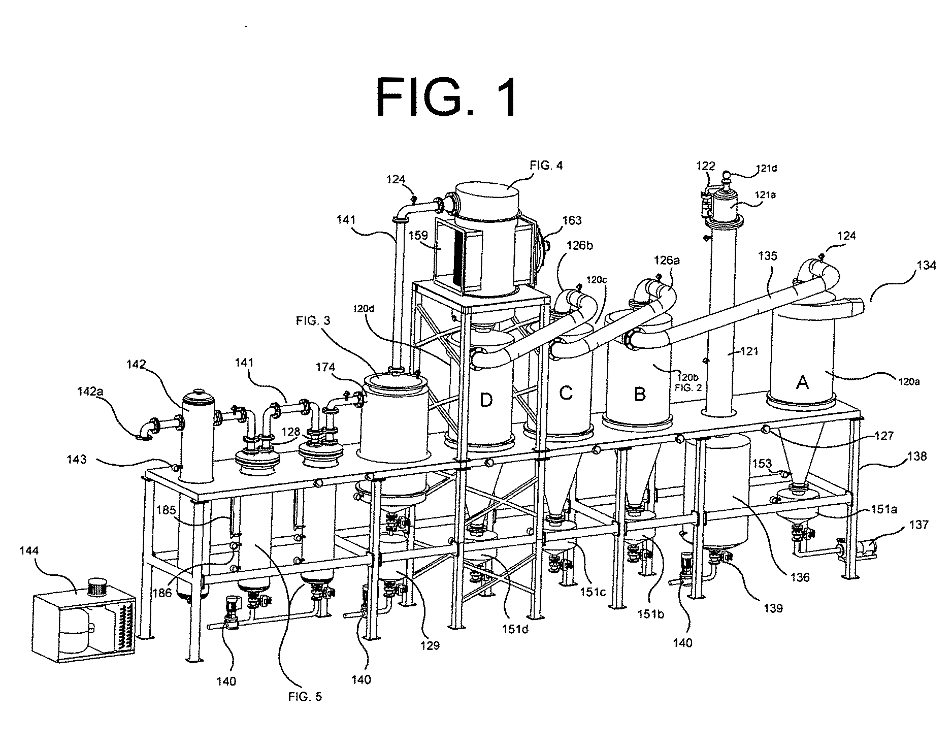
This application discloses material that is related to material disclosed in a provisional application filed on Dec. 9, 2014, and having serial number 62089628, titled “Cyclonic Condensation System”, incorporated herein in its entirety by reference. The present invention improves on heat exchanged technology as it does not require the bolting of the heat exchangers from end to end; takes up much less space than if the current technology was used; increases the surface area inside of the condensers that make up a heat exchanger; requires much lower velocity of the vapor when entering the condenser; allows for the continued release of the condensed liquid after the heat exchange and reaction, allowing the non-condensed vapors to move to the next condenser, and; prevents the build-up of char that could plug the tubes within the condensers. The use of heat exchangers as cooling systems is known. Examples of known devices include U.S. Pat. No. 4,858,681 to Sclzberger, U.S. Pat. No. 8,365,812 to Al-Hadhrami, U.S. Pat. No. 4,060,127 to Savin et. al., U.S. Pat. No. 3,168,136 to Ammon, and U.S. Pat. No. 3,258,068 to Hollister. These patents teach multi-stage heat exchangers to slowly cool a vapor. These patents use condensers that are bolted end to end on a slope so any liquid accumulating as a result of vapor condensation will flow down a slope or gradient. The problem with these designs is the amount of space required for these types of set-ups and the low surface area inside the condensers. These designs also do not allow for the daisy-chain design utilized in this invention so that the condensation of usable re-useable fuel vapors in optimized. This invention's Cyclonic Cooling System is part of a re-useable energy technology and the prior art designs would lead to Char build-up and plugging of the tubes within the condenser reducing effectiveness. The invention discussed herein differs from the prior art as it employs modified rotation fins, internal cyclone heat sinks, forced gas direction reversal inside of each cyclone, the ability to control fuel flash points without an external heat source, separation of the collected fuels without an external heat source, and compact low temperature coil cooler that uses one hundred percent of the cooling surface. The Cyclonic Cooling System consists of four cyclones, two fuel tanks, an air cooled radiator, one glycol chilled coil condenser, two bubblers, and one expansion tank all attached to a structural steel frame. The cyclones are constructed from 10 gauge stainless steel material. This material was selected due to its ability to withstand the internal pressure of the reactor while allowing heat to pass through the metal, cooling the incoming gas. The cyclones consist of a scrolled inlet, flanged body section, internal tube with fixed rotation fins, an interior baffle with reversed rotation fins, a bolted cone with support pads, and a discharge hopper with an outlet port. The internal rotation fins are welded to one side of the cyclone tube allowing for the condensed liquid to run through the fins to the discharge hopper. The internal tube also has a cone bottom to continue the vapor to pressurize inside the cyclone. Inside the internal tube is a cone drum that acts as a baffle. This baffle also has rotation fins welded to one side. The cone drum baffle has a sloped top to allow for drainage of any condensation that may occur inside. The gas inlet and outlet discharge ports have a flange connection. The cone bottom is equipped with a coupling that acts as a level indicator. The cone bottom has a discharge part with a stub in flange for rotation and connection to the discharge hopper. The discharge hopper has a drain port, two outlet ports and the level indicator coupling. The cyclones are piped in a daisy chain configuration. The piping used between cyclones is a thin wall schedule 10 stainless steel pipe with ANSI 150 flanges. This pipe is sloped from one cyclone to the next and downhill to drain any condensation vapors. The last cyclone in the daisy chain has an air cooled heat exchanger connected to the top discharge flange. This air cooled heat exchanger reduces the remaining vapor temperature and allows for liquid to condense and return to the last cyclone where it enters the discharge hopper. This air cooled heat exchanger is constructed from oval-shaped tubing. The oval-shaped tubing is welded to the top and bottom seal plate, openings in the seal plate are welded to the oval-shaped tubing to allow vapors to pass through the inside of the tubing. Housing surrounds the tubing section and connects to an inlet chamber and gas discharge chamber. The fan is connected to the tube section housing. This part of the system uses ambient air and forces it across the outside of the tubing to reduce the inside vapor temperature. The fuel tanks are constructed from heavy wall schedule 40 stainless steel pipe with pipe ends and connecting ports as needed to fill and discharge the incoming fuels. The top of the main tank has an expansion column to allow light vapors to be removed from the collected liquids below. The second tank is a standard holding tank with inlet and outlet connections plus a coupling for level indication. The large tank is constructed to allow for high temperature fuel storage and collects from the first three cyclones. The smaller tank will see low temperature fuels and is used to collect fuel from the last cyclone and the coil condenser. After the vapors leave the air cooled heat exchanger it enters into a chilled coil condenser. The coil condenser is located above the small fuel tank. The condenser consists of six 1 inch diameter stainless steel round tubes that have been rolled into a spiral. The spiral reduces the overall length of the 1 inch tubing to one tenth the length. The spiral shape also assists in the slowing of the incoming vapors by use of the turning static pressure. The coils are attached through a top and bottom flange plate. This assembly is inserted into a drum housing with matching flanges. The drum housing is filled with a glycol product that acts as the media for the heat exchange. The glycol remains resident inside this drum. A cooling coil is introduced into the drum which cools the glycol. In turn the glycol cools the 1 inch tubing that cools the vapors inside. The cooling coil is attached to a standard refrigeration system and remains closed loop through the glycol drum. The vapors passing through the 1 inch coils, cool, so the coil condenser allows the produced condensation to drip to the bottom in the collection chamber, exiting the device. The special flange connection at the bottom of the glycol drum allows for liquid to go in one direction and gas to go in another. The chamber between the glycol drum and the outside is where the remaining vapors travel. This zone also is cooled by the glycol thus it benefits from double cooling. The coil condenser is designed with bolted flange connections for access and service to all components of this equipment. The chilled gases leave the coil condenser then travel through two bubbler tanks. These tanks have an extended pipe from the inlet port that is submerged under the liquid water line. This submerged pipe causes back pressure to the system by resistance of the liquid in the bubbler tank. This is referred to as water column pressure and by using two tanks the height can be divided between each one. An example is if total water column back pressure is 60 inches in one bubbler and 50 inches in the second bubbler, a total of 110 inches of water column back pressure is created. These bubbler tanks can contain different liquid components as needed to remove any contaminants in the remaining vapors. The first tank is designed to hold water and is equipped with a level indicator and a PH meter to monitor the condition of the water. Water is used to remove sulfur and the buildup of sulfur will be indicated by a change in the PH. The second bubbler contains caustic soda which will capture any chlorine gas in the vapors. This is also monitored with a PH meter and this second bubbler is also equipped with a level indicator and level sensor. The last tank on the cyclone cooling system is a standard expansion tank that is designed to catch any liquid droplets that may travel through the piping. Pressure sensors and indicators mounted on this expansion tank keep track of the reactor pressure. Throughout the cyclone cooling system are differential pressure gauges. These gauges are used to identify any buildup or clog edge in the pipe or in any component of the cooling system. The entire process is mounted on a bolted steel frame system. The standard A36 carbon steel frame, painted and equipped with matching connection clips for all corresponding equipment. The size and shape of the equipment is designed for quick breakdown and transport in a standard sea container. It should be noted and understood that while the above and other advantages and results of the present invention will become apparent to those skilled in the art from the following detailed description and accompanying drawings, showing the contemplated novel construction, combinations, and elements herein described, and more particularly defined by the appended claims, it should be clearly understood that changes in the precise embodiments of the herein described invention are meant to be included within the scope of the claims, except insofar as they may be precluded by the prior art. The accompanying drawings illustrate preferred embodiments of the present invention according to the best mode presently devised for making and using the instant invention, and in which: While the invention will be described and disclosed herein connection with certain preferred embodiments, the description is not intended to limit the invention to the specific embodiments shown and described here, but rather the invention is intended to cover all alternative embodiments and modifications that fall within the spirit and scope of the invention as defined by claims included herein as well as any equivalents of the disclosed and claimed invention. The utility patent this application describes is a cooling system as depicted in Plastic waste material is shredded and fed into a pyrolysis reactor. Applying heat above 350 degrees Celsius will cause the shredded plastic material to melt and vaporize. The up-stream reactor requires back pressure to assist in the thermal cracking of the carbon chains present in the plastic material. The Cyclonic Cooling System depicted in The first cyclone The coil condenser is the design with bolted flange connections for access and service to all components of this equipment. Each cooling cyclone and the coil chiller has a tank or collection hopper below them The first three cyclones The chilled gases leave the coil condenser then travels to two bubbler tanks The last tank on the cyclone cooling system is a standard expansion tank By forcing the rotations, the hot gases will lose heat from thereto contact loss with the outside body Each cyclone collects vapor at a lower temperature than the one before it in the gas stream creating its own YFI value. Inside the internal tube The syn-gas is then passed through two sets or bubbler/scrubbers The next bubbler also acts as a back pressure device, flame arrester and scrubber. This time it is filled with caustic soda to scrub chorine. CI+NaOH=NaClO or salt and water. The bubblers At this point the syn-gas is ready to be used. The burners for the reactor use this fuel. The syn-gas may also be used to power a generator that could power the reactor's electrical system. The last item in the cooling system is a finish tank. This tanks act a drip collection if any liquids travel past the bubblers. It also serves as an expansion tank for the syn-gas. When the pressure inside this tank is at set point, the gas is allowed to be used. Fractionation, the process used by refineries to break down carbon chains of petroleum compounds so that the desired carbon compound can be achieved. This process typically involves high heat, distillation, re-boiling, and energy intensive cooling processes. This application discloses an invention that will condense vapor produced by a pyrolysis reactor. This system uses one standard cyclone; three cascading cyclones with internal cyclonic rotation fins that force incoming vapor to maintain a fixed amount of rotation regardless of the vapor's velocity, heat sinks that increase condensation, reversing fins that force gases to reverse direction inside the cyclone decreasing vapor velocity to increase heat loss; a main collection tank that allows for the controlling of the fuel flash point; a compact low temperature coil cooler that uses 100 percent of the cooling surface that allows for the production of higher quality fuel; and, bubblers/scrubbers that produce back pressure into the pyrolysis reactor. 1. An apparatus that is part of a reusable fuel processing unit, the assembly being used to cool the vapors produced by the pyrolysis reactor comprising;
Four cyclone coolers, two fuel tanks, an air cooled radiator, one glycol chilled coil condenser, two bubblers, and one expansion tank all attached to a structural steel frame where; The cyclone coolers are connected to each other in a daisy chain configuration where; The cyclones are connected in a daisy chain configuration by a cross over pipe where; The first cyclone in the daisy chain is a standard cyclone where; The fuel that is condensed in the first cyclone drops out of the first cyclone into a discharge hopper and the vapor that is not condensed in the first cyclone enters a cross over pipe where; The cross over pipe that the vapor enters is connected to a second cyclone where; The fuel that is condensed in the second cyclone is discharged into a main holding tank and the vapor that is not condensed in the second cyclone enters a cross over pipe where; The cross over pipe that the vapor enters is connected to a third cyclone where; The fuel that is condensed in the third cyclone is discharged into a main holding tank and the vapor that is not condensed in the third cyclone enters a cross over pipe where; The cross over pipe that the vapor enters is connected to a forth cyclone where; The fuel that is condensed in the fourth cyclone is discharged into a small holding tank and the vapor that is not condensed enters an Air Cooled Heat Exchanger where; The vapor that is condensed enters back into the forth cyclone and is discharged into a small holding tank that is beneath the forth cyclone and the vapor that is not condensed enter into a Coil Condenser where; The vapor that is condensed enters into a small light fuel tank and the vapor that is not condensed enters into two bubbler tanks where the any liquid droplets enter into a standard expansion tank. 2. The cyclones that are the second, third and fourth cyclones connected in a daisy chain where;
The three cyclones are configured in a daisy chain are constructed of 10 gauge stainless steel where; The cyclones consist of a scrolled inlet, flanged body section, internal tube with fixed rotation fins, an interior baffle with reversed rotation fins, a bolted cone with support pads, and a discharge hopper with an outlet port where; The internal rotation fins are welded to one side of the cyclone tube allowing for the condensed liquid to run through the fins to the discharge hopper where; The internal tube also has a cone bottom to continue the vapor to pressurize inside the cyclone where; Inside the internal tube is a cone drum that acts as a baffle where; This baffle also has rotation fins welded to one side where; The cone drum baffle has a sloped top to allow for drainage of any condensation that may occur inside where; The gas inlet and outlet discharge ports have a flange connection where; The cone &Mom is equipped with a coupling that acts as a level indicator where; The cone bottom has a discharge part with a stub in flange for rotation and connection to the discharge hopper where; The discharge hopper has a drain port, two outlet ports and the level indicator coupling where; The last cyclone in the daisy-chain has an air cooled heat exchanger connected to the top discharge flange. 3. The internal cyclonic rotational fins of the daisy-chain cyclones of 4. The heat sinks of the daisy-chain cyclones of 5. The reversing fins of the daisy-chain cyclones of 6. The Coil Condenser of REFERENCE TO RELATED APPLICATIONS
BACKGROUND OF THE INVENTION
(a) Field of the Invention
(b) Discussion of Known Art
SUMMARY
BRIEF DESCRIPTION OF THE DRAWINGS
DETAILED DESCRIPTION OF PREFERRED EXEMPLAR EMBODIMENTS