MOTOR DRIVEN COOLED COMPRESSOR SYSTEM
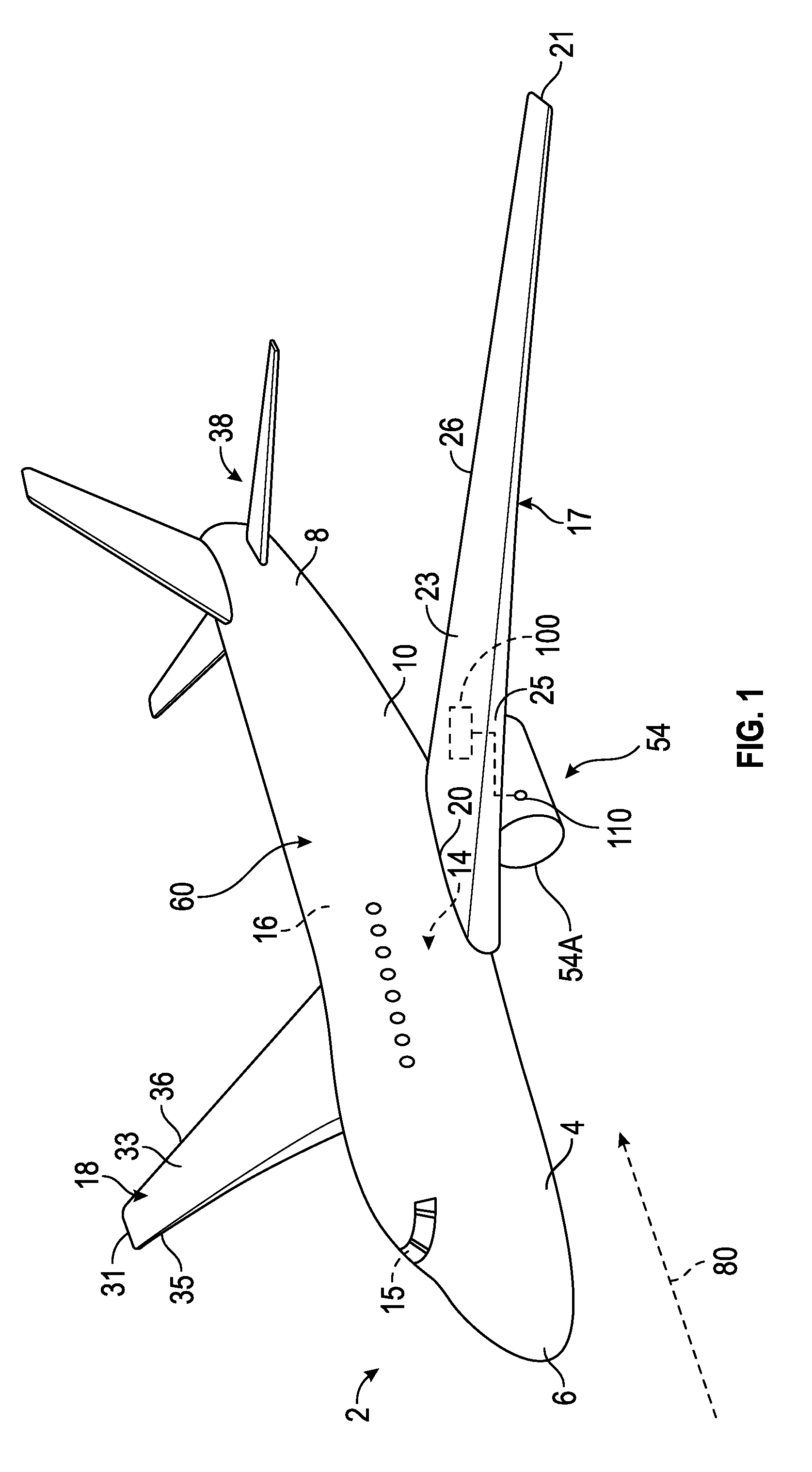
The subject matter disclosed herein generally relates to a compressors, and more specifically to an apparatus and a method for cooling a compressor system. Engineers are continuously trying to reduce drag on aircraft and other vehicles. Viscous drag is the frictional force between the air and the aircraft surface that occurs primarily in the boundary layer. In a laminar flow boundary layer, the air molecules at the aircraft surface are effectively stationary and then the velocity of the air molecules gradually increases moving away from the aircraft surface. If the laminar flow breaks away from the aircraft surface, a turbulent boundary layer is created. A turbulent boundary layer tends to increase viscous drag in comparison to a laminar flow. Various methods of boundary-layer flow control have been incorporated into aircraft to help induce laminar flow on the aircraft surface and thus reduce drag. One method to control the boundary-layer is called boundary layer suction, which utilizes air compressors to provide suction at selected point on the aircraft surface. The compressors can be powered by compact high power electric motors. The compressors must be cooled and a lightweight efficient solution is desired. According to one embodiment, a cooled compressor system is provided. The cooled compressor system including: a compressor that in operation compresses air; an electric motor that in operation drives the compressor, the electric motor having a back iron, a motor stator radially inward from the back iron, and a motor rotor radially inward from the motor stator; an airflow system fluidly connected to the compressor, the airflow system in operation directs air through the back iron and in between the motor stator and motor rotor; an airflow inlet that in operation allows an inflow of air to the airflow system; and an airflow outlet that in operation allows an outflow of air from the airflow system; wherein the air travels from the airflow inlet to the airflow outlet through the compressor and the airflow system. In addition to one or more of the features described above, or as an alternative, further embodiments of the cooled compressor system may include that the airflow system is fluidly connected to the airflow inlet through the compressor. In addition to one or more of the features described above, or as an alternative, further embodiments of the cooled compressor system may include that the compressor further includes a compressor inlet fluidly connected to the airflow inlet and a compressor outlet fluidly connected to the airflow system. In addition to one or more of the features described above, or as an alternative, further embodiments of the cooled compressor system may include that the airflow system is fluidly connected to the airflow outlet through the compressor. In addition to one or more of the features described above, or as an alternative, further embodiments of the cooled compressor system may include that the compressor further includes a compressor inlet fluidly connected to the airflow system and a compressor outlet fluidly connected to the airflow outlet. In addition to one or more of the features described above, or as an alternative, further embodiments of the cooled compressor system may include that the airflow inlet is located on the outer surface of an aircraft, the airflow inlet being in fluid communication with air located outside of the aircraft. In addition to one or more of the features described above, or as an alternative, further embodiments of the cooled compressor system may include that the airflow inlet is located on an engine nacelle of the aircraft. According to another embodiment, a method of assembling a cooled compressor system. The method of assembling the cooled compressor system including: operably connecting an electric motor to a compressor that in operation compresses air when driven by the electric motor, the electric motor having a back iron, a motor stator radially inward from the back iron, and a motor rotor radially inward from the motor stator; fluidly connecting an airflow system to the compressor, the airflow system in operation directs air through the back iron and in between the motor stator and motor rotor; fluidly connecting an airflow inlet to at least one of the compressor and the airflow system, the airflow inlet in operation allows an inflow of air to the airflow system; and fluidly connecting an airflow outlet to at least one of the compressor and the airflow system, the airflow outlet in operation allows an outflow of air from the airflow system; wherein the air travels from the airflow inlet to the airflow outlet through the compressor and the airflow system. In addition to one or more of the features described above, or as an alternative, further embodiments of the method of assembling a cooled compressor system may include that the airflow system is fluidly connected to the airflow inlet through the compressor. In addition to one or more of the features described above, or as an alternative, further embodiments of the method of assembling a cooled compressor system may include that the compressor further includes a compressor inlet fluidly connected to the airflow inlet and a compressor outlet fluidly connected to the airflow system. In addition to one or more of the features described above, or as an alternative, further embodiments of the method of assembling a cooled compressor system may include that the airflow system is fluidly connected to the airflow outlet through the compressor. In addition to one or more of the features described above, or as an alternative, further embodiments of the method of assembling a cooled compressor system may include that the compressor further includes a compressor inlet fluidly connected to the airflow system and a compressor outlet fluidly connected to the airflow outlet. In addition to one or more of the features described above, or as an alternative, further embodiments of the method of assembling a cooled compressor system may include installing the airflow inlet on the outer surface of an aircraft, the airflow inlet being in fluid communication with air located outside of the aircraft. In addition to one or more of the features described above, or as an alternative, further embodiments of the method of assembling a cooled compressor system may include that the airflow inlet is located on an engine nacelle of the aircraft. According to another embodiment, a method of operating a cooled compressor system is provided. The method of operating a cooled compressor system includes: powering an electric motor, the electric motor having a back iron, a motor stator radially inward from the back iron, and a motor rotor radially inward from the motor stator; driving a compressor using the electric motor; compressing air using the compressor; flowing air through the back iron and in between the motor stator and motor rotor using an airflow system fluidly connected to the compressor, the flowing air in operation cools the electric motor; allowing an inflow of air to the airflow system using an airflow inlet; and allowing an outflow of air from the airflow system using an airflow outlet; wherein the air travels from the airflow inlet to the airflow outlet through the compressor and the airflow system. In addition to one or more of the features described above, or as an alternative, further embodiments of the method of operating a cooled compressor system may include that the airflow system is fluidly connected to the airflow inlet through the compressor. In addition to one or more of the features described above, or as an alternative, further embodiments of the method of operating a cooled compressor system may include that the compressor further includes a compressor inlet fluidly connected to the airflow inlet and a compressor outlet fluidly connected to the airflow system. In addition to one or more of the features described above, or as an alternative, further embodiments of the method of operating a cooled compressor system may include that the airflow system is fluidly connected to the airflow outlet through the compressor. In addition to one or more of the features described above, or as an alternative, further embodiments of the method of operating a cooled compressor system may include that the compressor further includes a compressor inlet fluidly connected to the airflow system and a compressor outlet fluidly connected to the airflow outlet. In addition to one or more of the features described above, or as an alternative, further embodiments of the method of operating a cooled compressor system may include that the airflow inlet is located on the outer surface of an aircraft, the airflow inlet being in fluid communication with air located outside of the aircraft. Technical effects of embodiments of the present disclosure include utilizing compressor airflow to cool an electric motor driving the compressor. The foregoing features and elements may be combined in various combinations without exclusivity, unless expressly indicated otherwise. These features and elements as well as the operation thereof will become more apparent in light of the following description and the accompanying drawings. It should be understood, however, that the following description and drawings are intended to be illustrative and explanatory in nature and non-limiting. The following descriptions should not be considered limiting in any way. With reference to the accompanying drawings, like elements are numbered alike: The detailed description explains embodiments of the present disclosure, together with advantages and features, by way of example with reference to the drawings. A detailed description of one or more embodiments of the disclosed apparatus and method are presented herein by way of exemplification and not limitation with reference to the Figures. Referring now to The aircraft 2 includes a cooled compressor system 100 to provide boundary layer suction that in operation decreases drag. The compressor may provide boundary layer suction to any outer surface 60 of the aircraft 2 including but not limited to the fuselage 4, the wings 17, 18, tail portion 8, and engine nacelle 54 Referring now to The airflow system 180 in operation directs air through the back iron 156 and in between the motor stator 154 and motor rotor 152(i.e. through the gap 153). The airflow system 180 is thermally connected to the back iron 156, the motor stator 154, and motor rotor 152, thus as air flows through the airflow system 180, heat is removed from the back iron 156, the motor stator 154, and motor rotor 152. The back iron 156 may have cooling channels and/or cooling fins to enhance transfer of heat from the back iron 156 to the cooling flow of air 80. The flow of air 80 can also pass over the end windings 158 of the motor stator 154 to provide additional cooling to the motor stator 154. The airflow system 180 may be a series of fluidly connected pipes and/or channels to direct the flow of air 80 as previously described. The airflow system 180 is fluidly connected to the compressor 120. The airflow inlet 110 in operation allows an inflow of air 80 to the airflow system 180. As mentioned above the air may come from outside the aircraft 2 of The air 80 may be compressed by the compressor 120 first and then flow through the airflow system 180 or the air 80 may flow through the airflow system 180 first and then get compressed by the compressor 120. In an embodiment, as seen in the example of Advantageously, the efficient design of the cooled compressor system 100 in the present disclosure allows for sufficient cooling of the electric motor 150 while eliminating the need for complex ducting to provide air from a source other than the cooled compressor system 100. Advantageously, increased cooling capacity may result by pulling the air 80 through the airflow system 180 first and then compressing the air 80, as seen in Referring now to At block 404, the electric motor 150 is powered. As mentioned above, the electric motor 150 comprises a back iron 156, a motor stator 154 radially inward from the back iron 156, and a motor rotor 152 radially inward from the motor stator 154. A gap 153 exists between the motor stator 154 and the motor rotor 152. At block 406, the electric motor 150 drives the compressor 120, which allows the compressor 120 to compress air 80 at block 408. At block 410, the air 80 is flowed through the back iron and in between the motor stator 154 and motor rotor 152 using the airflow system 180 that is fluidly connected to the compressor 120. The flowing air 80 in operation cools the electric motor 150 by absorbing heat from the electric motor 150. At block 412, the airflow inlet 110 allows an inflow of air 80 to the airflow system 180. As mentioned above, the inflow of air 80 may be pulled from air 80 external to an aircraft 2. At block 414, the airflow outlet 170 allows an outflow of air 80 from the airflow system 180. As mentioned above, the outflow of air 80 may lead expel air from the aircraft 2. While the above description has described the flow process of Referring now to At block 504, the electric motor 150 is operably connected to the compressor 120. As mentioned above, the compressor 120 in operation compresses air 80 when driven by the electric motor 150. As also mentioned above, the electric motor 150 includes a back iron 156, a motor stator 154 radially inward from the back iron 156, and a motor rotor 152 radially inward from the motor stator 154. At block 506, the airflow system 180 is fluidly connected to the compressor 120. The airflow system 180 in operation directs air 80 through the back iron 156 and in between the motor stator 154 and motor rotor 152. At block 508, the airflow inlet 110 is fluidly connected to at least one of the compressor 120 and the airflow system 180. In the example of At block 510, the airflow outlet 170 is fluidly connected to at least one of the compressor 120 and the airflow system 180. In the example of While the above description has described the flow process of The term “about” is intended to include the degree of error associated with measurement of the particular quantity based upon the equipment available at the time of filing the application. For example, “about” can include a range of ±8% or 5%, or 2% of a given value. The terminology used herein is for the purpose of describing particular embodiments only and is not intended to be limiting of the present disclosure. As used herein, the singular forms “a”, “an” and “the” are intended to include the plural forms as well, unless the context clearly indicates otherwise. It will be further understood that the terms “comprises” and/or “comprising,” when used in this specification, specify the presence of stated features, integers, steps, operations, elements, and/or components, but do not preclude the presence or addition of one or more other features, integers, steps, operations, element components, and/or groups thereof. While the present disclosure has been described with reference to an exemplary embodiment or embodiments, it will be understood by those skilled in the art that various changes may be made and equivalents may be substituted for elements thereof without departing from the scope of the present disclosure. In addition, many modifications may be made to adapt a particular situation or material to the teachings of the present disclosure without departing from the essential scope thereof. Therefore, it is intended that the present disclosure not be limited to the particular embodiment disclosed as the best mode contemplated for carrying out this present disclosure, but that the present disclosure will include all embodiments falling within the scope of the claims. A cooled compressor system is provided including: a compressor that in operation compresses air; an electric motor that in operation drives the compressor, the electric motor having a back iron, a motor stator radially inward from the back iron, and a motor rotor radially inward from the motor stator; an airflow system fluidly connected to the compressor, the airflow system in operation directs air through the back iron and in between the motor stator and motor rotor; an airflow inlet that in operation allows an inflow of air to the airflow system; and an airflow outlet that in operation allows an outflow of air from the airflow system; wherein the air travels from the airflow inlet to the airflow outlet through the compressor and the airflow system. 1. A cooled compressor system comprising:
a compressor that in operation compresses air; an electric motor that in operation drives the compressor, the electric motor having a back iron, a motor stator radially inward from the back iron, and a motor rotor radially inward from the motor stator; an airflow system fluidly connected to the compressor, the airflow system in operation directs air through the back iron and in between the motor stator and motor rotor; an airflow inlet that in operation allows an inflow of air to the airflow system; and an airflow outlet that in operation allows an outflow of air from the airflow system; wherein the air travels from the airflow inlet to the airflow outlet through the compressor and the airflow system. 2. The cooled compressor system of the airflow system is fluidly connected to the airflow inlet through the compressor. 3. The cooled compressor system of the compressor further includes a compressor inlet fluidly connected to the airflow inlet and a compressor outlet fluidly connected to the airflow system. 4. The cooled compressor system of the airflow system is fluidly connected to the airflow outlet through the compressor. 5. The cooled compressor system of the compressor further includes a compressor inlet fluidly connected to the airflow system and a compressor outlet fluidly connected to the airflow outlet. 6. The cooled compressor system of the airflow inlet is located on the outer surface of an aircraft, the airflow inlet being in fluid communication with air located outside of the aircraft. 7. The cooled compressor system of the airflow inlet is located on an engine nacelle of the aircraft. 8. A method of assembling a cooled compressor system comprising:
operably connecting an electric motor to a compressor that in operation compresses air when driven by the electric motor, the electric motor having a back iron, a motor stator radially inward from the back iron, and a motor rotor radially inward from the motor stator; fluidly connecting an airflow system to the compressor, the airflow system in operation directs air through the back iron and in between the motor stator and motor rotor; fluidly connecting an airflow inlet to at least one of the compressor and the airflow system, the airflow inlet in operation allows an inflow of air to the airflow system; and fluidly connecting an airflow outlet to at least one of the compressor and the airflow system, the airflow outlet in operation allows an outflow of air from the airflow system; wherein the air travels from the airflow inlet to the airflow outlet through the compressor and the airflow system. 9. The method of the airflow system is fluidly connected to the airflow inlet through the compressor. 10. The method of the compressor further includes a compressor inlet fluidly connected to the airflow inlet and a compressor outlet fluidly connected to the airflow system. 11. The method of the airflow system is fluidly connected to the airflow outlet through the compressor. 12. The method of the compressor further includes a compressor inlet fluidly connected to the airflow system and a compressor outlet fluidly connected to the airflow outlet. 13. The method of installing the airflow inlet on the outer surface of an aircraft, the airflow inlet being in fluid communication with air located outside of the aircraft. 14. The method of the airflow inlet is located on an engine nacelle of the aircraft. 15. A method of operating a cooled compressor system comprising:
powering an electric motor, the electric motor having a back iron, a motor stator radially inward from the back iron, and a motor rotor radially inward from the motor stator; driving a compressor using the electric motor; compressing air using the compressor; flowing air through the back iron and in between the motor stator and motor rotor using an airflow system fluidly connected to the compressor, the flowing air in operation cools the electric motor; allowing an inflow of air to the airflow system using an airflow inlet; and allowing an outflow of air from the airflow system using an airflow outlet; wherein the air travels from the airflow inlet to the airflow outlet through the compressor and the airflow system. 16. The method of the airflow system is fluidly connected to the airflow inlet through the compressor. 17. The method of the compressor further includes a compressor inlet fluidly connected to the airflow inlet and a compressor outlet fluidly connected to the airflow system. 18. The method of the airflow system is fluidly connected to the airflow outlet through the compressor. 19. The method of the compressor further includes a compressor inlet fluidly connected to the airflow system and a compressor outlet fluidly connected to the airflow outlet. 20. The method of the airflow inlet is located on the outer surface of an aircraft, the airflow inlet being in fluid communication with air located outside of the aircraft.BACKGROUND
BRIEF DESCRIPTION
BRIEF DESCRIPTION OF THE DRAWINGS
DETAILED DESCRIPTION