SPIRAL MIXING CHAMBER WITH VORTEX GENERATING OBSTRUCTIONS
This application claims benefit to provisional patent application Ser. No. 62/434,683 (911-029.1-2/X-ATI-0002US), filed 15 Dec. 2016, which is incorporated by reference in its entirety. This invention relates to a technique for mixing a gas and a liquid. Typically devices that dissolve gases into fluids do so by means of a pressure tank and a compressor. The gas and liquid are held in a tank at a high pressure for a length of time sufficient to saturate the dissolution of the gas into the liquid. These devices require expensive components, generally consume a large amount of power, are large, have many components, and are typically loud. In summary, the present invention is a passive device whose purpose is to mix gases into a liquid by taking advantage of turbulent mixing instead of time and power. The device is a spiral mixing chamber that includes obstructions in the flow path that create eddies of the appropriate length scale to efficiently break up gas bubbles suspended in the fluid. This efficient break up and mixing of the liquid and gas is augmented by the secondary flow created by the curvature of the spiral. The dimensions of the flow path and of the obstructions can change throughout the device in order to cause the creation of a wide range of turbulent eddy length scales and ensure that bubbles of many sizes are broken down and mixed into the fluid. According to some embodiments, the present invention may include, or take the form of, a spiral mixing chamber for dissolving a gas into a liquid, featuring a new and unique combination of a cap and a mixing plate. The cap may include a gas injector configured to receive gas. The mixing plate may include:
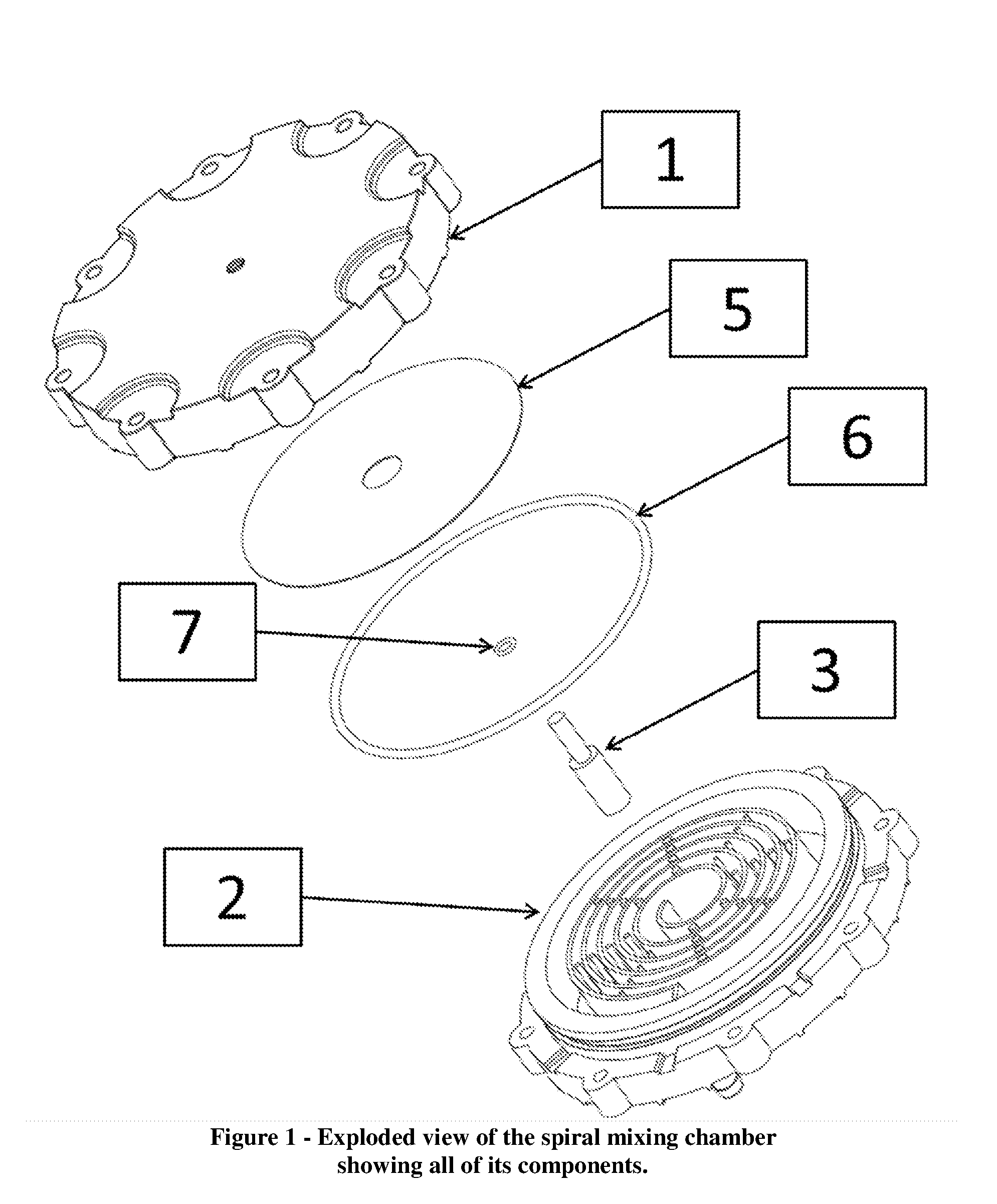
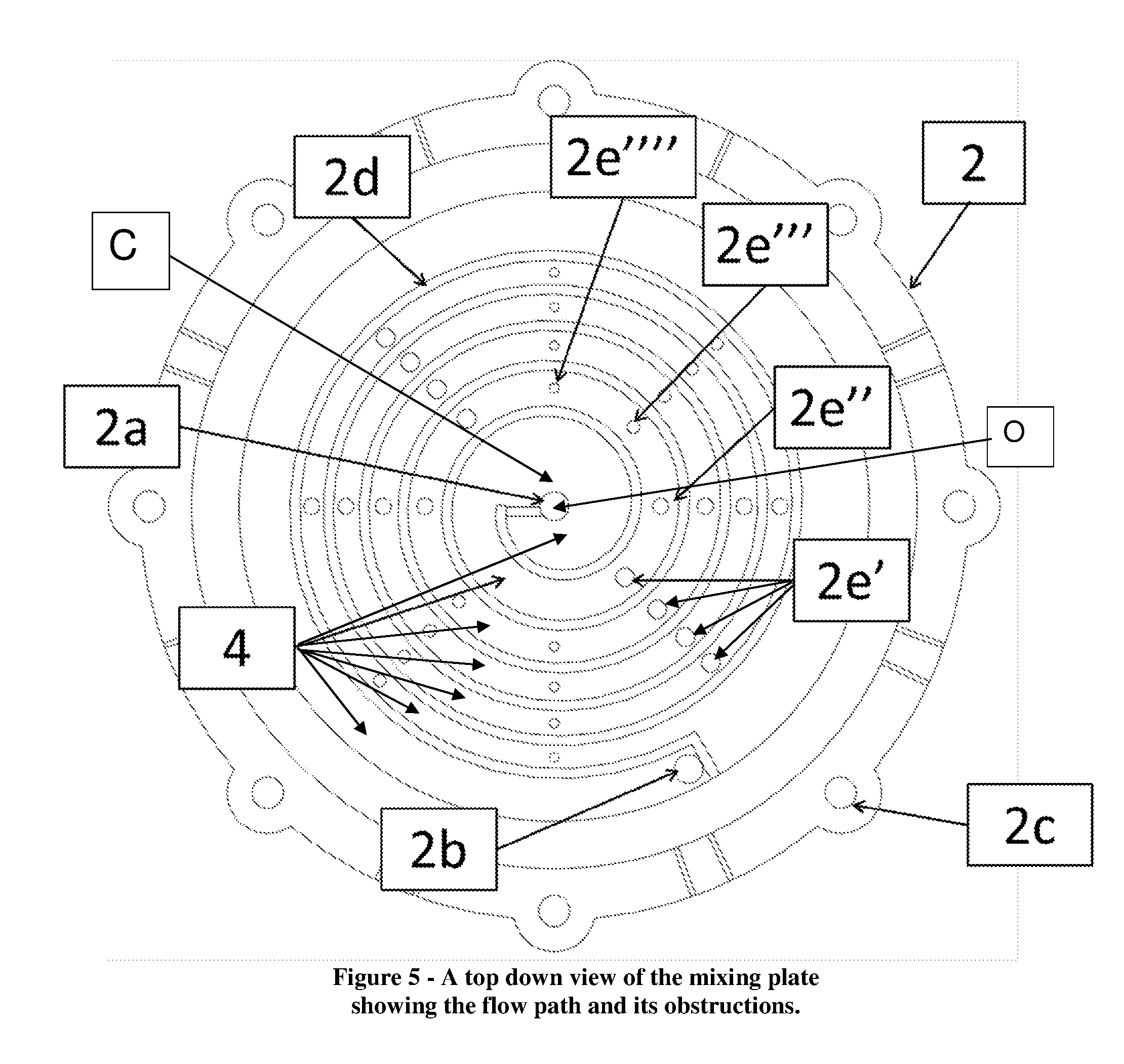
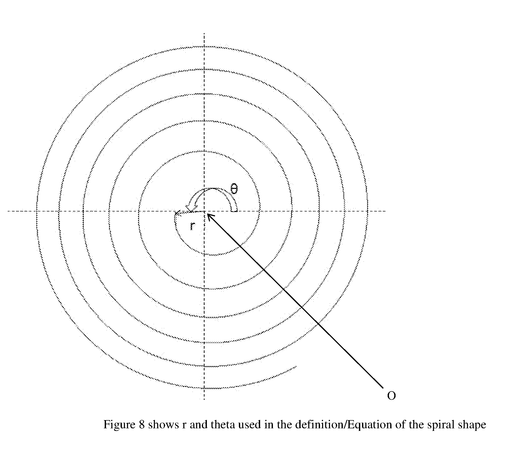
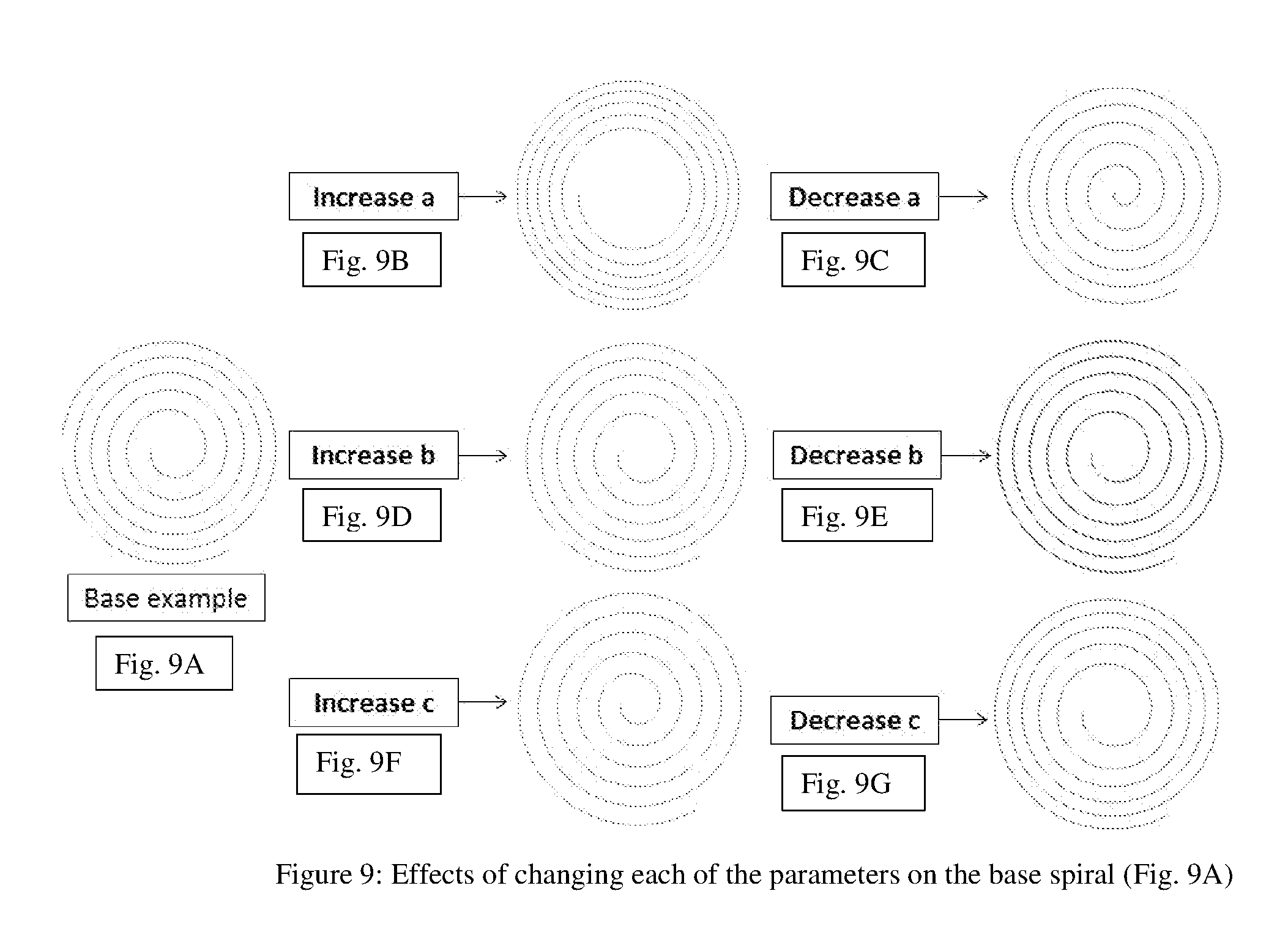
The present invention may include one or more of the following features: The dimensions of the flow path and of the flow path obstructions can change throughout the flow path, e.g., in order to cause the creation of a wide range of turbulent eddy length scales and ensure that bubbles of many sizes are broken down and mixed into the fluid. The flow path obstructions may include cylindrical flow path obstructions having different diameters that are configured or placed in the flow path in order to mix a range of bubble diameters, although the scope of the invention is not intended to be limited to any particular geometric shape, e.g., including a triangular shape, oval shape, square shape, etc. As the flow path winds away from the central gas and liquid receiving area or chamber, the flow path obstructions may change in size, shape or dimension, e.g., including alternately increasing and/or decreasing in size, dimension or diameter. By way of example, as the flow path winds away from the central gas and liquid receiving area or chamber to the mixture outlet, the flow path obstructions may include a repeating series of four flow path obstructions that decrease in size, dimension or diameter. According to some embodiments, the spiral geometry may be configured to create a main flow that has a component tangential to the spiral and a secondary flow which is in a direction perpendicular to the spiral geometry, including where the secondary flow enhances the mixing of the gas and the liquid relative to, or when compared to, a straight flow pathway. According to some embodiments, the spiral may be defined by the equation: where r and θ are polar coordinates based on a coordinate system whose origin O lies at the center of the spiral (see where the constants a, b, and c define the geometry of the spiral, including where the parameter a determines the starting distance of the radius of the spiral from the origin O, the parameter b determines the tightness or turn of the spiral, and the parameter c determines the rate of change of the curvature of the spiral, also known as the distance between successive turns. According to some embodiments, the spiral may take the form or an Archimedean spiral, or a logarithmic spiral, e.g., including where the width of the flow path stays the same or changes as the flow path winds away from the central gas and liquid receiving area or chamber to the mixture outlet. According to some embodiments, the flow path obstructions may be configured in the flow path at a series of polar coordinates defined along one or more rays extending from a central chamber to an outer periphery of the spiral or flow path. The one or more rays may extend from the central chamber of the spiral may include eight arrays, each array having at least four flow path obstructions, including where at least four flow path obstructions have the same size, dimension or diameter. The eight arrays may be configured and spaced at polar coordinate angles that include 0°, 45°, 90°, 135°, 180°, 225°, 270°, 315° extending from the central chamber of the spiral, including where each array has at least four flow path obstructions with the same size, dimension or diameter. By way of example, the eight arrays may include first arrays at the polar coordinate angles of 0° and 180° having a first size, dimension or diameter; second arrays at the polar coordinate angles of 45° and 225° having a second size, dimension or diameter; third arrays at the polar coordinate angles of 90° and 270° having a third size, dimension or diameter; and fourth arrays at the polar coordinate angles of 135° and 315° having a fourth size, dimension or diameter, all consistent with that disclosed herein. Moreover, embodiments are envisioned, and the scope of the invention is intended to include, implementing flow path obstructions along the flow path having the same size, dimension or diameter; having the same or different geometric shapes, etc. According to some embodiments, the flow path has a cross sectional area; and the cross sectional area of the flow-path may change along the length of the spiral, e.g. which changes the average fluid velocity and results in a changing Reynold's number along the flow path. According to some embodiments, the flow path may include the central gas and liquid receiving chamber at the beginning of the flow path; the cap may include a central inner portion; and the gas injector may be configured at the central inner portion to provide the gas into the central gas and liquid receiving chamber. According to some embodiments, the flow path may include the central gas and liquid receiving chamber at the beginning of the flow path; the mixing plate may include a corresponding central inner portion; and the liquid inlet may be configured at the corresponding central inner portion to provide the liquid into the central gas and liquid receiving chamber. According to some embodiments, the flow path may include a flow path provisioning chamber at the end of the flow path; the mixing plate may include a corresponding central inner portion and an outer peripheral portion; the liquid inlet may be configured at the corresponding central inner portion to provide the liquid into the central gas and liquid receiving chamber; and the mixture outlet may be configured at the outer peripheral portion to provide the mixture of the gas and liquid from the spiral mixing chamber. According to some embodiments, the flow path may include the central gas and liquid receiving chamber at the beginning of the flow path; the gas injector may be configured to receive and provide a forced gas into the central gas and liquid receiving chamber; the liquid inlet may be configured to receive and provide a forced liquid into the central gas and liquid receiving chamber; and the forced gas and the forced liquid may be provided into the central gas and liquid receiving chamber at a pre-defined ratio. According to some embodiments, the gas injector may include, or take the form of, a carb-stone which is a porous device that forces the gas through and produces very small bubbles. Alternatively, the gas injector may include, or take the form of, a sintered steel cylinder that includes holes configured or formed therein that allow for the assumption of a distributed gas mass flow rate. According to some embodiments, the spiral mixing chamber may include a gasket arranged between the cap and the mixing plate configured to seal the flow path. According to some embodiments, the spiral mixing chamber may include an inner O-ring arranged between an inner surface of the cap and a rim-like portion of the gas injector configured to provide an inner seal between the cap and the gas injector. According to some embodiments, the cap may include a gap injector opening configured or formed therein to receive at least part of the gas injector. According to some embodiments, the spiral mixing chamber may include an outer O-ring arranged between a peripheral rim of the mixing plate and a corresponding peripheral rim of the cap and configured to provide an outer seal between the mixing plate and the cap. According to some embodiments, the present invention may include a method for dissolving a gas into a liquid using a mixing chamber, featuring: configuring a cap with a gas injector to receive gas; and configuring a mixing plate having
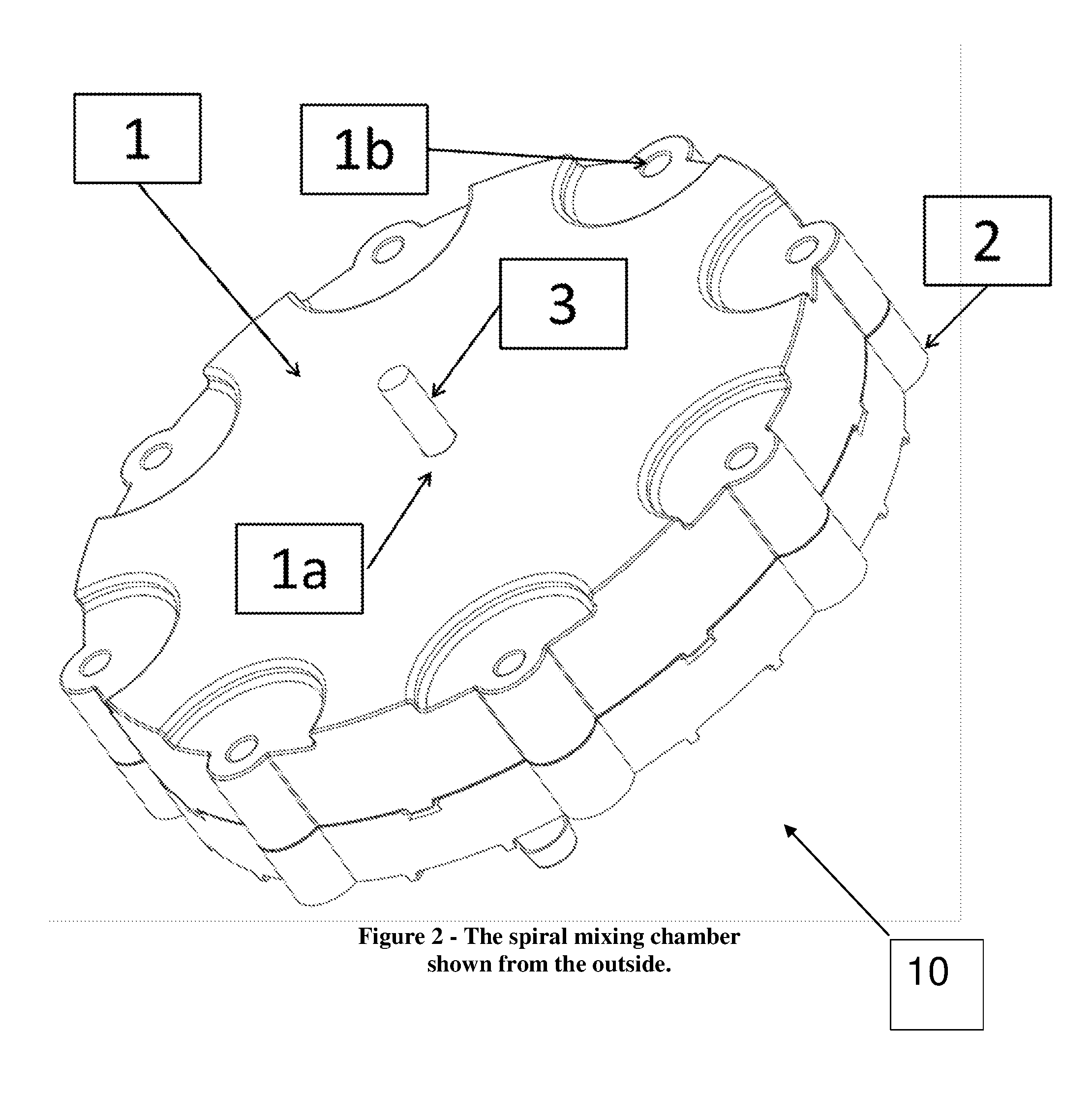
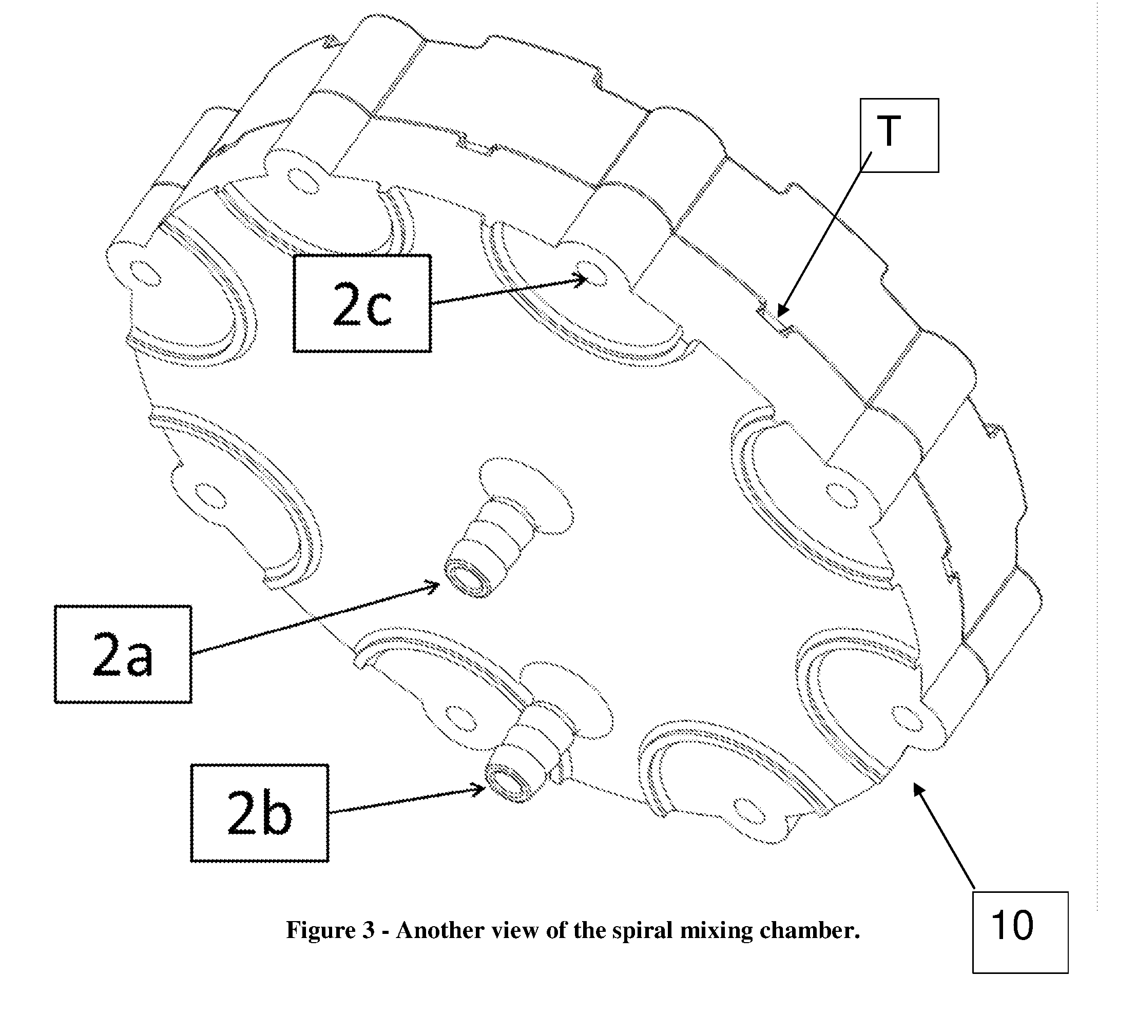
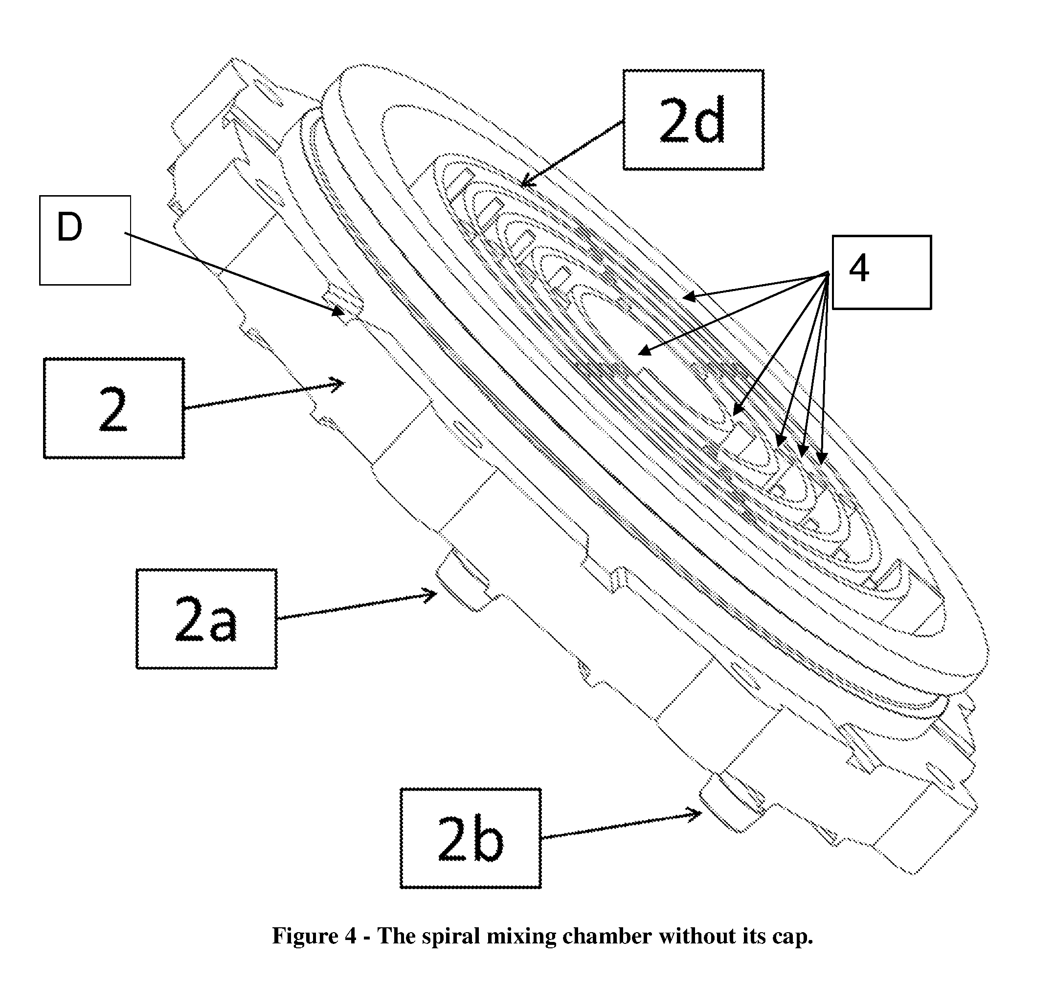
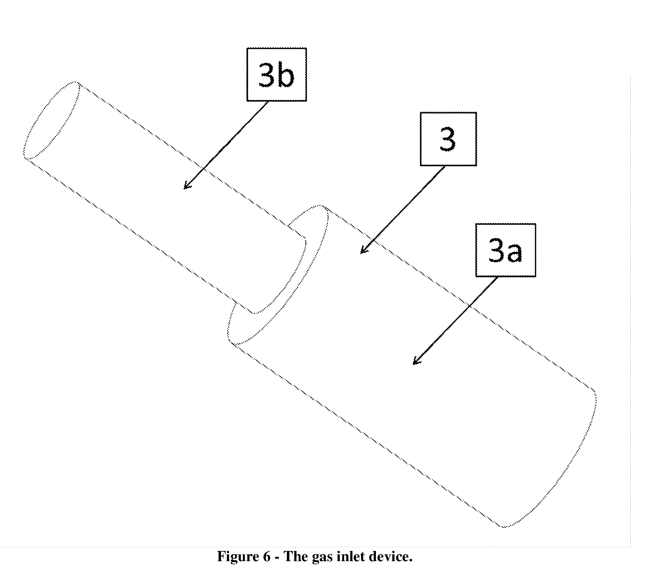
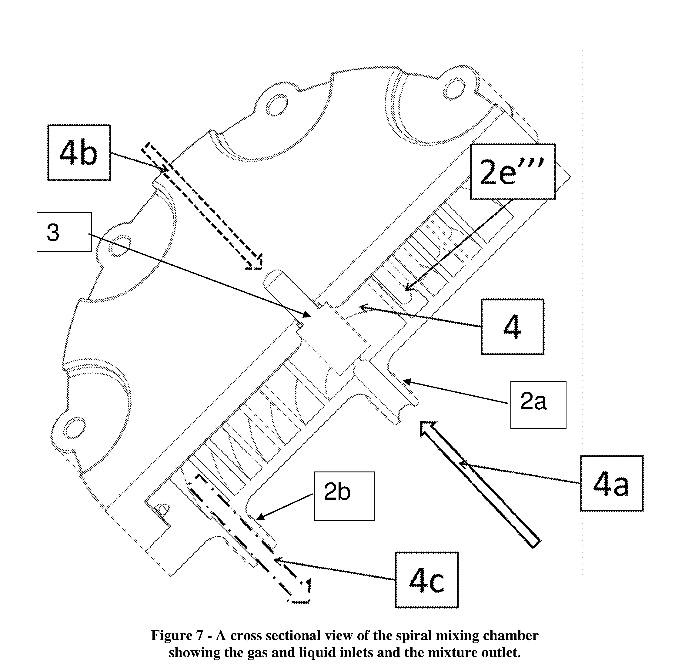
The method may include one or more of the other features set forth herein. The drawing, which are not necessarily drawn to scale, includes To reduce clutter in the drawing, each Figure in the drawing does not necessarily include every reference label for every element shown therein. The purpose of the spiral mixing chamber or device (10) is to dissolve the gas into the liquid into a predetermined concentration as quickly and efficiently as possible. To achieve this dissolution, the liquid and the gas may be forced under pressure into the spiral mixing chamber (10), e.g., at a pre-defined ratio through the liquid inlet (2 Generally, it is understood that bubbles suspended in a flow path like element (4) may be broken up most efficiently by turbulent vortices, e.g., whose length scale is about the same as the average diameter of the bubble. In effect, the flow past a flow path obstruction, e.g., shaped as a cylinder, results in a turbulent wake, and the length scale of the vortices produced can be predicted reasonably accurately by knowing the Reynolds number of the flow going past the cylinder as well as the diameter of the cylinder. According to some embodiments of the present invention, several cylindrical flow path obstructions (e.g., like elements (2 By way of example, and consistent with that disclosed herein, the spiral can be described using the equation: where r and θ are polar coordinates based on a coordinate system whose origin lies at the center of the spiral; and where the constants a, b, and c define the geometry of the spiral, including where the parameter a determines the starting distance of the radius of the spiral from the origin O, the parameter b determines the tightness or turn of the spiral, and the parameter c determines the rate of change of the curvature of the spiral, also known as the distance between successive turns. See When put into contact with each other, the gas will dissolve into the liquid until it reaches an equilibrium state. The rate at which the gas will dissolve into the liquid is determined by the concentration of the gas in the liquid and the surface area of contact between the two at the current time, the higher the concentration the slower the dissolution. According to some embodiments, the gas injector (3) may take the form of a commonly known device, e.g., such as a carb-stone which is a porous device that forces gas through from its inlet to its outlet and produces very small bubbles. This technique alone produces a high surface area of contact between the gas and the liquid which enhances the rate of dissolution. The enhanced mixing causes the bubbles to come in contact with fresh liquid again speeding up the dissolution. The flow path obstructions (2 According to some embodiments, the spiral mixing chamber or device can be optimized for specific gases, liquids, flow rates, pressures, and concentrations by changing the spiral geometry and obstruction geometry. According to some embodiments, the cap (1) may include a peripheral rim having tabs (T) configured or formed therein; and the mixing plate (2) may include corresponding peripheral rim having detents (D) configured or formed therein to receive the tabs (T) for coupling the cap (1) and mixing plate (2) together for preventing rotation. Techniques for pressurizing gases and liquids are known in the art, and the scope of the invention is not intended to be limited to any particular type or kind thereof, e.g., either now known or later developed in the future. For example, pumps may be configured to provide gases and liquids under pressure. Possible applications include the following: Carbonation of beverages, Nitrogenator of beverages, or Oxygenation of liquids. Applications also include the addition of Ozone to water for sanitation purposes. While the invention has been described with reference to an exemplary embodiment, it will be understood by those skilled in the art that various changes may be made and equivalents may be substituted for elements thereof without departing from the scope of the invention. In addition, may modifications may be made to adapt a particular situation or material to the teachings of the invention without departing from the essential scope thereof. Therefore, it is intended that the invention not be limited to the particular embodiment(s) disclosed herein as the best mode contemplated for carrying out this invention. A spiral mixing chamber for dissolving a gas into a liquid, features a new and unique combination of a cap and a mixing plate. The cap may include a gas injector configured to receive gas. The mixing plate may include: a liquid inlet configured to receive liquid, a mixture outlet configured to provide a mixture of the gas and liquid from the spiral mixing chamber, and a flow path configured as a spiral geometry having a spiral that winds in a continuous and gradual curve around a central point from the liquid inlet to the mixture outlet, the flow path having flow path obstructions configured to cause disturbances in the flow which generates turbulent vortices that work to break apart bubbles in the mixture flowing through the spiral mixing chamber or device. 1. A spiral mixing chamber for dissolving a gas into a liquid, comprising:
a cap having a gas injector configured to receive gas; and a mixing plate having a liquid inlet configured to receive liquid, having a mixture outlet configured to provide a mixture of the gas and liquid from the spiral mixing chamber, and having a flow path configured as a spiral geometry having a spiral that winds in a continuous and gradual curve around a central point from the liquid inlet to the mixture outlet, the flow path having flow path obstructions configured to cause disturbances in the flow which generates turbulent vortices that work to break apart bubbles in the mixture flowing through the spiral mixing chamber or device. 2. A spiral mixing chamber according to 3. A spiral mixing chamber according to where r and θ are polar coordinates based on a coordinate system whose origin O lies at the center of the spiral; and where the constants a, b, and c define the geometry of the spiral, including where the parameter a determines the starting distance of the radius of the spiral from the origin O, the parameter b determines the tightness or turn of the spiral, and the parameter c determines the rate of change of the curvature of the spiral. 4. A spiral mixing chamber according to 5. A spiral mixing chamber according to 6. A spiral mixing chamber according to 7. A spiral mixing chamber according to 8. A spiral mixing chamber according to 9. A spiral mixing chamber according to the flow path has a cross sectional area; and the cross sectional area of the flow-path changes along the length of the spiral which changes the average fluid velocity and results in a changing Reynold's number along the flow path. 10. A spiral mixing chamber according to 11. A spiral mixing chamber according to 12. A spiral mixing chamber according to 13. A spiral mixing chamber according to 14. A spiral mixing chamber according to 15. A spiral mixing chamber according to 16. A spiral mixing chamber according to 17. A spiral mixing chamber according to the flow path includes a central gas and liquid receiving chamber at the beginning of the flow path; the cap includes a central inner portion; the gas injector is configured at the central inner portion to provide the gas into the central gas and liquid receiving chamber. 18. A spiral mixing chamber according to the flow path includes a central gas and liquid receiving chamber at the beginning of the flow path; the mixing plate includes a corresponding central inner portion; and the liquid inlet is configured at the corresponding central inner portion to provide the liquid into the central gas and liquid receiving chamber. 19. A spiral mixing chamber according to the flow path includes a flow path provisioning chamber at the end of the flow path; the mixing plate includes a corresponding central inner portion and an outer peripheral portion; the liquid inlet is configured at the corresponding central inner portion to provide the liquid into the central gas and liquid receiving chamber; and the mixture outlet is configured at the outer peripheral portion to provide the mixture of the gas and liquid from the spiral mixing chamber. 20. A spiral mixing chamber according to the mixing plate includes corresponding mixing plate holes configured or formed therein to receive the fasteners/bolts for coupling the cap and mixing plate together. 21. A spiral mixing chamber according to the cap includes a peripheral rim having tabs configured or formed therein; and the mixing plate includes corresponding peripheral rim having detents configured or formed therein to receive the tabs for coupling the cap and mixing plate together and preventing rotation. 22. A spiral mixing chamber according to the flow path includes a central gas and liquid receiving chamber at the beginning of the flow path; the gas injector is configured to receive and provide a forced gas into the central gas and liquid receiving chamber; the liquid inlet is configured to receive and provide a forced liquid into the central gas and liquid receiving chamber; and the forced gas and the forced liquid are provided into the central gas and liquid receiving chamber at a pre-defined ratio. 23. A method for dissolving a gas into a liquid using a mixing chamber, comprising:
configuring a cap with a gas injector to receive gas; and configuring a mixing plate having
a liquid inlet to receive liquid, a mixture outlet to provide a mixture of the gas and liquid from the spiral mixing chamber, and a flow path with a spiral geometry having a spiral that winds in a continuous and gradual curve around a central point from the liquid inlet to the mixture outlet, the flow path having flow path obstructions configured to cause disturbances in the flow which generates turbulent vortices that work to break apart bubbles in the mixture flowing through the spiral mixing chamber or device.CROSS-REFERENCE TO RELATED APPLICATIONS
BACKGROUND OF THE INVENTION
1. Field of Invention
2. Description of Related Art
SUMMARY OF THE INVENTION
Specific Embodiments
The Flow Path Obstructions
The Spiral
The Flow Path
The Gas Injector and Other Components
The Method
BRIEF DESCRIPTION OF THE DRAWING
DETAILED DESCRIPTION OF BEST MODE OF THE INVENTION
The Detents and Tabs
Techniques for Pressurizing Gases and Liquids
Possible Applications
The Scope of the Invention