Hybrid Vehicle
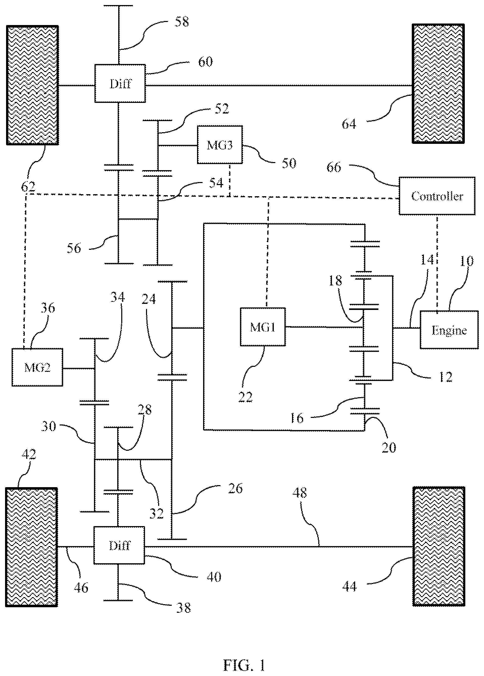
This disclosure relates to the field of hybrid electric vehicle controls. More particularly, the disclosure pertains to a method of controlling the rear wheel torque of a four wheel drive hybrid electric vehicle. Many vehicles are used over a wide range of vehicle speeds, including both forward and reverse movement. Some types of engines, however, are capable of operating efficiently only within a narrow range of speeds. Consequently, transmissions capable of efficiently transmitting power at a variety of speed ratios are frequently employed. When the vehicle is at low speed, the transmission is usually operated at a high speed ratio such that it multiplies the engine torque for improved acceleration. At high vehicle speed, operating the transmission at a low speed ratio permits an engine speed associated with quiet, fuel efficient cruising. Hybrid vehicle transmissions improve fuel economy by providing energy storage. In a hybrid electric vehicle, for example, energy may be stored in a battery. The battery may be charged by operating the engine to produce more power than instantaneously required for propulsion. Additionally, energy that would otherwise be dissipated during braking can be captured and stored in the battery. The stored energy may be used later, allowing the engine to produce less power than instantaneously required for propulsion and thereby consuming less fuel. In two wheel drive vehicles, propulsion is provided by only the front wheels or only the rear wheels. In a four wheel drive vehicle, in contrast, all four wheels provide propulsion. Four wheel drive vehicles can improve mobility on surfaces with variable and margin coefficient of friction because some wheels retain traction when other wheels slip. A vehicle includes first and second axles and a controller. The first axle is powered by a first powertrain. The second axle is powered by a first electric motor. The first powertrain may include an internal combustion engine and a second electric motor. A planetary gear set may include a sun gear fixedly coupled to the second motor, a carrier fixedly coupled to the internal combustion engine, and a ring gear drivably connected to the first axle. A third electric motor may be driveably connected to the first axle. The controller is programmed to adjust a torque of the first electric motor in response to the state of the second axle. Specifically, in response to traction at the second axle, the controller adjusts a torque of the first electric motor to a driver demand based torque level. In response to slip of the second axle, the controller adjusts the torque of the first electric motor to a speed control torque level. During a transition between the driver demand based torque level and the speed control torque level, the controller sets a rate of change of torque of the first electric motor to mitigate noise, vibration, and harshness associated with rapid torque changes. A method of controlling a hybrid vehicle sets a first motor torque based on a state of a first axle. The first motor torque is set to a first driver demand based torque level in response to traction at a first axle. The first motor torque is set to a speed control based torque level in response to slip of the first axle. The method transitions from the first driver demand based torque level to the speed control based torque level at a first controlled rate. The method may also transition from the speed control based torque level to the first driver demand based torque level at a second controlled rate. The transition from the speed control based torque level to the first driver demand based torque level may be in response to an absolute value of the first motor torque exceeding an absolute value of the driver demand based torque level or in response to an absolute value of the driver demand based torque level being less than a threshold. A powertrain torque to a second axle may be set to a second driver demand based torque level. Embodiments of the present disclosure are described herein. It is to be understood, however, that the disclosed embodiments are merely examples and other embodiments can take various and alternative forms. The figures are not necessarily to scale; some features could be exaggerated or minimized to show details of particular components. Therefore, specific structural and functional details disclosed herein are not to be interpreted as limiting, but merely as a representative basis for teaching one skilled in the art to variously employ the present invention. As those of ordinary skill in the art will understand, various features illustrated and described with reference to any one of the figures can be combined with features illustrated in one or more other figures to produce embodiments that are not explicitly illustrated or described. The combinations of features illustrated provide representative embodiments for typical applications. Various combinations and modifications of the features consistent with the teachings of this disclosure, however, could be desired for particular applications or implementations. Electric machine 50, labelled MG3, drives a rear axle. MG3 is fixedly coupled to layshaft gear 52 which meshes with layshaft gear 54. Layshaft gear 54 is fixedly coupled to layshaft gear 56 which meshed with layshaft gear 58. Layshaft gear 58 is the input to differential 60. Differential 60 drives rear wheels 62 and 64 allowing slight speed differences as the vehicle turns a corner. Electric machines 22, 36, and 50 are reversible electric machines. Each of these electric machines is capable of converting electrical power to mechanical power or converting mechanical power to electrical power. For example, each machine may be a synchronous motor in combination with an inverter. In some circumstances, engine 10 may generate more power than is delivered to the vehicle wheels with the excess power stored in a battery (not shown). In other circumstances, power may flow from the battery permitting engine 10 to produce less power than the instantaneous demand of the vehicle. For example, the engine 10 may be off while power to propel the vehicles comes from the battery. Power to the front axle may come from a combination of engine power and battery power. Power to the rear axle comes exclusively from the battery. The powertrain of where Tengis the torque generated by engine 10, TMG1is the torque absorbed by electric machine 22, Tgear24is the torque absorbed by gear 24, Nsunis the number of teeth on sun gear 18, and Nringis the number of teeth on ring gear 20. The engine speed is a weighted average of the generator speed and the speed of gear 24. When the vehicle is moving slowly, gear 24 rotates slowly and generator 22 rotates faster than engine 10. Power generated by the engine is split by the planetary gear set. A portion of the power is transmitted mechanically to shaft 32 from carrier 14 to ring gear 20 to gear 24 to gear 26. The remaining power is transmitted from sun 18 to generator 22 which converts the power to electrical power. Motor 36 converts the electrical power to mechanical power which is transmitted to shaft 32 by gear 34 and 30. The torque of engine 10 and electric machines 22, 36, and 50 are set by a controller 66. The controller receives input from a variety of sensors, including driver manipulated sensors including an accelerator pedal, brake pedal, and steering wheel. From these sensors, the controller determines a driver demanded torque and then calculates how much torque each machine should be directed to produce, as discussed below. Alternatively, the vehicle may be an autonomous vehicle, in which case the controller directly computes the desired wheel torque in response to sensed traffic and road conditions. In the case of an autonomous vehicle, the term driver demanded torque means the controller calculated total desired wheel torque. The additional sensors indicate vehicle speed, axle speed (defined as the average of the corresponding wheels speeds), yaw rate, and lateral acceleration, among other parameters. Controller 66 may be a single microprocessor or multiple communicating microprocessors. The vehicle may be operated in an All Wheel Drive (AWD) mode. In the AWD mode, a portion of the driver demanded torque is directed to the front axle and the remainder of the driver demanded torque is directed to the rear axle. In AWD mode, the tires are less likely to lose traction because each tire is transmitting less torque than in a two wheel drive mode. Furthermore, if one of the wheels does lose traction, the vehicle is still propelled by the wheels that retain traction. Also, vehicle handling may be improved. During braking, MG2 and MG3 may be commanded to generate negative torque such that vehicle kinetic energy is captured as electrical energy and stored in the battery. At 74, the controller decides whether to use sped control mode or torque control mode in the current time step. If the speed control mode is TRUE, either from a previous step or due to step 88, then the controller checks a series of conditions for staying in speed control mode. At 90, the controller compares the current measured MG3 torque to the torque control torque command. If the measured torque is larger, in absolute value, then the speed control trigger is set to FALSE at 92. At 94, the controller compares the driver request to a threshold. If the driver request is less, in absolute value, then the speed control trigger is set to FALSE at 92. Finally, at 96, the controller set the speed control trigger to FALSE if the gear position is something other than drive, reverse, or low. Returning now to At 108, the controller sets the MG2 torque request according to a process for transitioning from speed control to torque control. This transition process is illustrated by the flowchart of Returning now to Returning to Operating MG3 in the manner described above has several advantages. When the rear wheels have good traction, the MG3 torque is determined based on driver demand. As a result, the total driver demanded torque is distributed between the front and rear wheels. With the torque distributed, the wheels are less likely to lose traction when encountering a road surface with a marginal coefficient of friction. When the rear wheels have lost traction, the MG3 torque is controlled in a speed control mode with the speed target based primarily on vehicle speed. In the speed control mode, the rear wheel torque is controlled to facilitate regaining traction and to keep the vehicle moving through a slippery patch. The transitions between these two operating modes are not abrupt. Instead, the torque changes at a steady, predetermined rate. This predetermined rate is calibrated to mitigate noise, vibration, and harshness concerns that may occur when the rear wheel torque changes too abruptly. While exemplary embodiments are described above, it is not intended that these embodiments describe all possible forms encompassed by the claims. The words used in the specification are words of description rather than limitation, and it is understood that various changes can be made without departing from the spirit and scope of the disclosure. As previously described, the features of various embodiments can be combined to form further embodiments of the invention that may not be explicitly described or illustrated. While various embodiments could have been described as providing advantages or being preferred over other embodiments or prior art implementations with respect to one or more desired characteristics, those of ordinary skill in the art recognize that one or more features or characteristics can be compromised to achieve desired overall system attributes, which depend on the specific application and implementation. As such, embodiments described as less desirable than other embodiments or prior art implementations with respect to one or more characteristics are not outside the scope of the disclosure and can be desirable for particular applications. One axle of a hybrid vehicle is powered by an electric motor while a second axle of the vehicle is powered by a powertrain that includes an internal combustion engine. The electrically driven axle can be controlled in a speed control mode or in a torque control mode based on a driver demanded torque. The speed control mode is used when slip is detected at the electrically driven axle. The torque control mode is used when the electrically driven axle has traction. During a transition between these modes, the rate of change of torque is controlled to a predetermined level to mitigate noise, vibration, and harshness. 1. A vehicle comprising:
a first axle powered by a first powertrain; a second axle powered by a first electric motor; and a controller programmed to
in response to traction at the second axle, adjust a torque of the first electric motor to a driver demand based torque level, in response to slip of the second axle, adjust the torque of the first electric motor to a speed control torque level, and during a transition between the driver demand based torque level and the speed control torque level, set a rate of change of torque of the first electric motor to mitigate noise, vibration, and harshness associated with rapid torque changes. 2. The vehicle of an internal combustion engine; and a second electric motor. 3. The vehicle of a planetary gear set having a sun gear fixedly coupled to the second electric motor, a carrier fixedly coupled to the internal combustion engine, and a ring gear driveably connected to the first axle; and a third electric motor drivably connected to the first axle. 4. A method of controlling a hybrid vehicle comprising:
setting a first motor torque to a first driver demand based torque level in response to traction at a first axle; setting the first motor torque to a speed control based torque level in response to slip of the first axle; and transitioning from the first driver demand based torque level to the speed control based torque level at a first controlled rate. 5. The method of 6. The method of 7. The method of 8. The method of 9. The method of 10. The method of 11. A method of controlling an electrically driven axle comprising:
setting a motor torque to a driver demand based torque level in response to traction at the axle; setting the motor torque to a speed control based torque level in response to slip of the axle; and transitioning from the driver demand based torque level to the speed control based torque level at a first controlled rate. 12. The method of 13. The method of 14. The method of TECHNICAL FIELD
BACKGROUND
SUMMARY OF THE DISCLOSURE
BRIEF DESCRIPTION OF THE DRAWINGS
DETAILED DESCRIPTION