COMPRESSOR HAVING CENTRIFUGATION AND DIFFERENTIAL PRESSURE STRUCTURE FOR OIL SUPPLYING
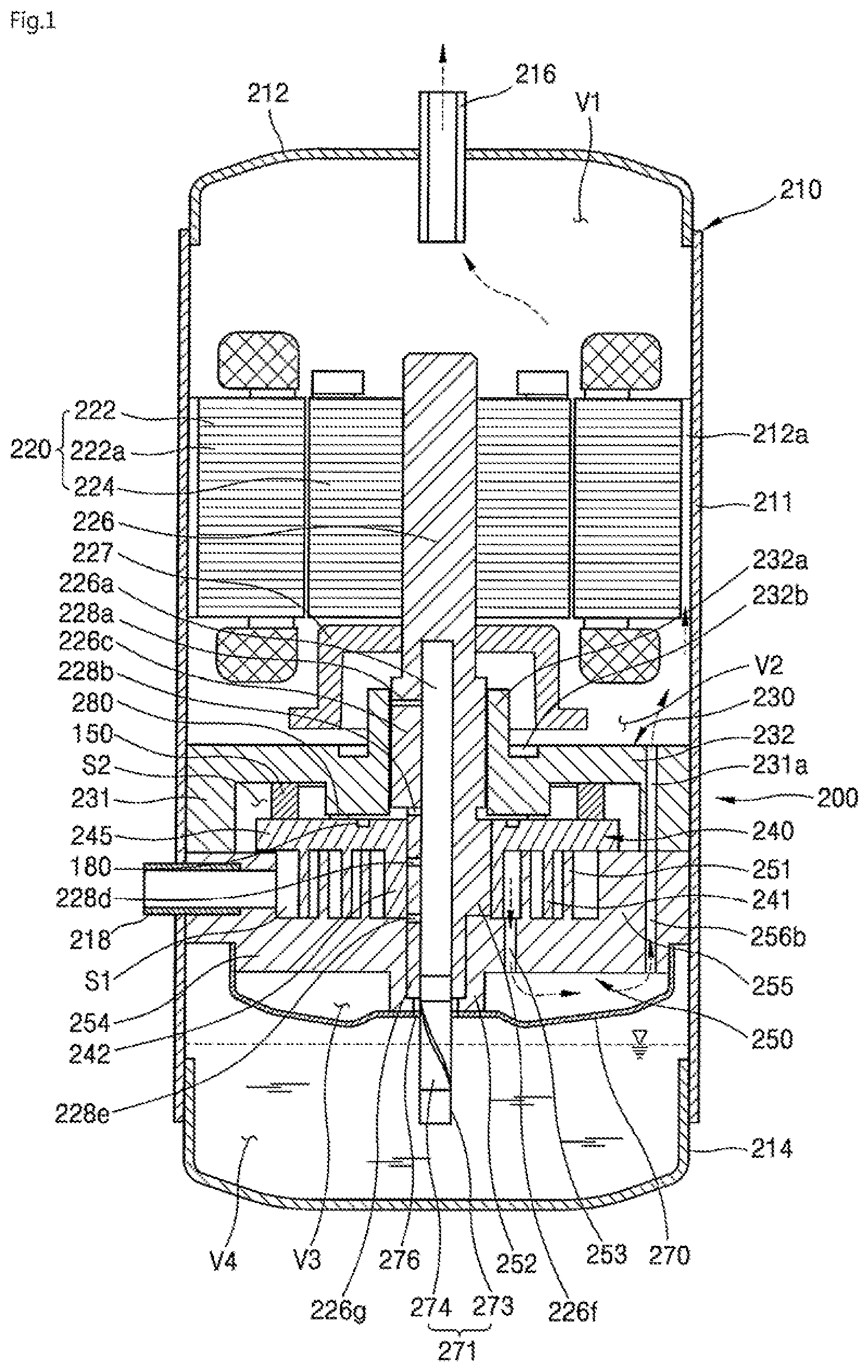
This application is a Continuation Application of prior U.S. patent application Ser. No. 15/830,135 filed Dec. 4, 2017, which claims priority under 35 U.S.C. § 119 to Korean Application No. 10-2017-0075041 filed on Jun. 14, 2017, whose entire disclosures are hereby incorporated by reference. A compressor having a centrifugation and differential pressure structure for supplying oil is disclosed herein. Generally, a compressor is applied to a vapor compression type refrigeration cycle (hereinafter, referred to as a “refrigeration cycle”) used for a refrigerator, or an air conditioner, for example. Compressors may be classified into reciprocating compressors, rotary compressors, and scroll compressors, for example, according to a method of compressing a refrigerant. The scroll compressor among the above-described compressors is a compressor which performs an orbiting movement by engaging an orbiting scroll with a fixed scroll fixed inside of a sealed container so that a compression chamber is formed between a fixed wrap of the fixed scroll and an orbiting wrap of the orbiting scroll. The scroll compressor is widely used for compressing a refrigerant in an air conditioner, for example, because the scroll compressor can obtain a relatively higher compression ratio than the other types of compressors and can obtain a stable torque because suction, compression, and discharge strokes of the refrigerant are smooth and continuous. Such scroll compressors may be classified into upper compression type compressors or lower compression type compressors according to a location of a drive motor and a compression component. The compression component is located at a higher level than the drive motor in the upper compression type compressor, and the compression component is located at a lower level than the drive motor in the lower compression type compressor. In the lower compression type scroll compressor, as there is a short distance between an oil storage chamber and the compression component, oil may be relatively uniformly supplied thereto; however, it may be structurally difficult to supply the oil thereto. More particularly, in a lower compression type scroll compressor which is driven at various speeds from low to high speed, it is important to optimize performance and secure reliability of a bearing portion according to a flow rate of oil. Accordingly, a structural improvement for supplying oil is required for portions, such as a bearing surface or compression chamber, to which it is structurally difficult to supply oil. Embodiments will be described in detail with reference to the following drawings in which like reference numerals refer to like elements, and wherein: Hereinafter, embodiments will be described with reference to accompanying drawings. Where possible, like or similar reference numerals in the drawings have been used to indicate like or similar elements, and repetitive disclosure has been omitted. Hereinafter, a scroll compressor according to an embodiment will be described with reference to The inner space of the casing 210 may be divided into a first space V1, which may be provided at an upper side of the drive motor 220, a second space V2 between the drive motor 220 and the compression device 200, a third space V3 partitioned by a discharge cover 270, and an oil storage chamber V4, which may be provided under the compression device 200. The casing 210, for example, may have a cylindrical shape, and thus, the casing 210 may include a cylindrical shell 211. An upper shell or cover 212 may be installed or provided on or at an upper portion of the cylindrical shell 211, and a lower shell or cover 214 may be installed or provided on or at a lower portion of the cylindrical shell 211. The upper and lower shells 212 and 214 may be coupled to the cylindrical shell 211 by welding, for example, and may form the inner space thereof. A refrigerant discharge pipe 216 may be installed or provided in the upper shell 212. The refrigerant discharge pipe 216 may form a path through which a compressed refrigerant discharged from the compression device 200 into the second space V2 and the first space V1 may be discharged to the outside. An oil separator (not shown) configured to separate oil mixed with the discharged refrigerant may be connected to the refrigerant discharge pipe 216. The lower shell 214 may form the oil storage chamber V4 capable of storing oil therein. The oil storage chamber V4 may serve as an oil chamber from which the oil may be supplied to the compression device 200 so that the compressor may be smoothly operated. A refrigerant suction pipe 218, which may form a path through which a refrigerant to be compressed may be introduced, may be installed or provided in or at a side surface of the cylindrical shell 211. The refrigerant suction pipe 218 may be installed or provided to penetrate up to a compression chamber S1 along a side surface of a fixed scroll 250. The drive motor 220 may be installed or provided in or at an upper portion inside of the casing 210. The drive motor 220 may include a stator 222 and a rotor 224. The stator 222, for example, may have a cylindrical shape, and may be fixed to the casing 210. A plurality of slots (not shown) may be formed in an inner circumferential surface of the stator 222 in a circumferential direction, and a coil 222 The rotor 224 may be coupled to an inside of the stator 222 and may generate rotational power. Also, the rotary shaft 226 may be press-fitted into a center of the rotor 224 so that the rotary shaft 226 may rotate with the rotor 224. The rotational power generated by the power rotor 224 may be transmitted to the compression device 200 through the rotary shaft 226. The compression device 200 may include a main frame 230, the fixed scroll 250, an orbiting scroll 240, and the discharge cover 270. The compression device 200 may further include an Oldham's ring 150. The Oldham's ring 150 may be installed or provided between the orbiting scroll 240 and the main frame 230. The Oldham's ring 150 may prevent rotation of the orbiting scroll 240 and allow orbiting movement of the orbiting scroll 240 on the fixed scroll 250. The main frame 230 may be provided under the drive motor 220 and may form an upper portion of the compression device 200. The main frame 230 may include a frame end plate (hereinafter, a “first end plate”) 232 having a circular shape, a frame bearing section (hereinafter, a “first bearing section”) 232 The first sidewall 231 may include a frame discharge hole (hereinafter, a “first discharge hole”) 231 The first bearing section 232 An oil pocket 232 The back pressure chamber S2 may include a medium pressure region, that is, a medium pressure chamber, and an oil supply path 226 In addition, the main frame 230 may be coupled to the fixed scroll 250 to form a space in which the orbiting scroll 240 may be rotatably installed or provided. That is, such a structure may be a structure which covers the rotary shaft 226 to transmit rotational power to the compression device 200 through the rotary shaft 226. The fixed scroll 250 forming a first scroll may be coupled to a lower surface of the main frame 230. More specifically, the fixed scroll 250 may be provided below the main frame 230. The fixed scroll 250 may include a fixed scroll end plate (a “second end plate”) 254 having a substantially circular shape, a fixed scroll sidewall (hereinafter, a “second sidewall”) 255 that protrudes upward from an outer circumferential portion of the second end plate 254, a fixed wrap 251 that protrudes from an upper surface of the second end plate 254 and is engaged with an orbiting wrap 241 of the orbiting scroll 240, which will be described hereinafter, to form the compression chamber S1, and a fixed scroll bearing section (hereinafter, a “second bearing section”) 252 formed at a center of a rear surface of the second end plate 254 and through which the rotary shaft 226 may pass. A discharge hole 253 configured to guide a compressed refrigerant from the compression chamber S1 to an inner space of the discharge cover 270 may be formed in the second end plate 254. In addition, a position of the discharge hole 253 may be arbitrarily determined in consideration of a required discharging pressure, for example. As the discharge hole 253 is formed to face the lower shell 214, the discharge cover 270 for accommodating a discharged refrigerant and guiding the discharged refrigerant to the fixed scroll discharge hole 256 The second sidewall 255 may include a fixed scroll discharge hole (hereinafter, a “second discharge hole”) 256 The third space V3 may communicate with the second space V2 using the second discharge hole 256 The second bearing section 252 may protrude from a lower surface of the second end plate 254 toward the oil storage chamber V4. The second bearing section 252 may include the second bearing portion so that the sub-bearing portion 226 The orbiting scroll 240 forming a second scroll may be installed or provided between the main frame 230 and the fixed scroll 250. More specifically, the orbiting scroll 240 may be coupled to the rotary shaft 226, to perform an orbiting movement and form two compression chambers S1, that is, a pair of compression chambers S1, between the orbiting scroll 240 and the fixed scroll 250. The orbiting scroll 240 may include an orbiting scroll end plate (hereinafter, a “third end plate”) 245 having a substantially circular shape, the orbiting wrap 241 which protrudes from a lower surface of the third end plate 245 and is engaged with the fixed wrap 251, and a rotary shaft coupler 242 provided at a center of the third end plate 245 and rotatably coupled to an eccentric portion 226 A pocket groove 180 to guide oil discharged through oil holes 228 As illustrated in the drawing, one pocket groove 180 may be formed at each of both sides of the rotary shaft 226; however, a plurality of pocket grooves 180 may also be formed at each of both sides of the rotary shaft 226. When the plurality of pocket grooves 180 is formed, the plurality of pocket grooves may be spaced a predetermined distance from each other on the upper surface of the third end plate 245 between the back pressure seal 280 and the rotary shaft 226. The pocket groove 180 may also be formed around the rotary shaft 226 in a circular shape on the upper surface of the third end plate 245 between the back pressure seal 280 and the rotary shaft 226. An outer circumferential portion of the rotary shaft coupler 242 may be connected to the orbiting wrap 241 to form the compression chamber S1 with the fixed wrap 251 during a compression process. The fixed wrap 251 and the orbiting wrap 241 may be formed in an involute shape, but may also be formed in any of various shapes other than the involute shape. The term “involute shape” refers to a curved line corresponding to a trajectory drawn by an end of a thread when the thread wound around a base circle having an arbitrary radius is released. The eccentric portion 226 The term “radial direction” may refer to a direction, that is, a lateral direction, perpendicular to an axial direction, that is, a vertical direction. More specifically, the radial direction may refer to a direction from an outside of the rotary shaft to an inside thereof. As described above, when the eccentric portion 226 Accordingly, the rotary shaft 226 may transmit a rotational force of the drive motor 220 to the orbiting scroll 240 of the compression device 200. In addition, the orbiting scroll 240 eccentrically coupled to the rotary shaft 226 may perform an orbiting movement with respect to the fixed scroll 250 using the transmitted rotational force. A main bearing portion 226 The main bearing portion 226 Conversely, the eccentric portion 226 The oil supply path 226 The first oil hole 228 In addition, the first oil hole 228 Unlike the drawing, a plurality of first oil holes 228 A first oil groove 229 Unlike the drawing, a plurality of first oil grooves 229 In addition, when the plurality of first oil grooves 229 The second oil hole 228 The first small diameter portion 54 may be provided to secure processability for forming the main bearing portion 226 Unlike the drawing, a plurality of second oil holes 228 The third oil hole 228 Unlike the drawing, a plurality third oil holes 228 A second oil groove 229 However, the third oil hole 228 Unlike the drawing, a plurality of second oil grooves 229 Lastly, the fourth oil hole 228 The second small diameter portion 55 may be provided to secure processability for forming the eccentric portion 226 Unlike the drawing, a plurality of fourth oil holes 226 Thus, oil guided upward through the oil supply path 226 Additional oil holes (not shown) may pass from the oil supply path 226 The oil feeder 271 that pumps oil from the oil storage chamber V4 may be coupled to a lower end of the rotary shaft 226, that is, a lower end of the sub-bearing portion 226 Although not illustrated in the drawing, a trochoid pump (not shown) may be coupled to the sub-bearing portion 226 A balance weight 227 that suppresses noise and vibration may be coupled to the rotor 224 or the rotary shaft 226. The balance weight 227 may be provided between the drive motor 220 and the compression device 200, that is, in the second space V2. Am operation process of the scroll compressor according to an embodiment will be described hereinafter. When power is applied to the drive motor 220 and a rotational force is generated, the rotary shaft 226 coupled to the rotor 224 of the drive motor 220 is rotated. Accordingly, the orbiting scroll 240 eccentrically coupled to the rotary shaft 226 may perform an orbiting movement with respect to the fixed scroll 250 and form the compression chamber S1 between the orbiting wrap 241 and the fixed wrap 251. The compression chamber S1 may be continuously formed in several steps such that a volume thereof gradually decreases toward a center thereof. Then, a refrigerant supplied from outside of the casing 210 through the refrigerant suction pipe 218 may directly flow into the compression chamber S1. The refrigerant may be compressed while being moved toward a discharge chamber of the compression chamber S1 by the orbiting movement of the orbiting scroll 240 to be discharged from the discharge chamber to the third space V3 through the discharge hole 253 of the fixed scroll 250. Next, a series of processes in which the compressed refrigerant discharged to the third space V3 is discharged to the inner space of the casing 210 through the second discharge hole 256 Hereinafter, a structure for supplying oil of the scroll compressor of As illustrated in As described above, the oil stored in the oil storage chamber V4 may be guided upward through the rotary shaft 226 and easily supplied to the bearing portion, that is, the bearing surface, through the plurality of oil holes 228 The oil guided upward through the oil supply path 226 That is, as illustrated in The oil guided to the medium pressure chamber S2 may be supplied to a thrust surface of the fixed scroll 250 and the Oldham's ring 150 installed between the orbiting scroll 240 and the main frame 230. That is, the oil that flows into the medium pressure chamber S2 may be sufficiently supplied to the thrust surface of the fixed scroll 250 and the Oldham's ring 150. Accordingly, wear of the thrust surface of the fixed scroll 250 and the Oldham's ring 150 may be reduced. The oil guided to the medium pressure chamber S2 may be guided to a differential pressure path 301 that supplies oil included in the fixed scroll 250. More specifically, the fixed scroll 250 of the scroll compressor of The differential pressure path 301 may pass through the second sidewall 255 and the second end plate 254; however, embodiments are not limited thereto. That is, the differential pressure path 301 may pass through only the second sidewall 255. In this case, the differential pressure path 301 may have a shorter length than the differential pressure path 301 which passes through both the second sidewall 255 and the second end plate 254. One or a first end of the differential pressure path 301 may communicate with the medium pressure chamber S2, and the other or a second end of the differential pressure path 301 may communicate with the compression chamber S1. Accordingly, oil guided to the differential pressure path 301 may be supplied to the compression chamber S1. As described above, the oil stored in the oil storage chamber V4 may be easily supplied to the compression chamber S1 through the pocket groove 180 and the differential pressure path 301. As oil is easily supplied to the compression chamber S1, wear due to friction between the orbiting scroll 240 and the fixed scroll 250 may be reduced so that compression efficiency may be improved. The oil supplied to the compression chamber S1 may form an oil film between the fixed scroll 250 and the orbiting scroll 240 to maintain a hermetic state therebetween. Further, the oil supplied to the compression chamber S1 may also absorb frictional heat generated by friction between the fixed scroll 250 and the orbiting scroll 240 to dissipate the heat. Hereinafter, structure for supplying oil of the scroll compressor of The main frame 230 of the scroll compressor of The first differential pressure path 311 may bypass the medium pressure chamber S2, that is, pass through the first end plate 232 and the first sidewall 231. That is, one or a first end of the first differential pressure path 311 may be connected to a high-pressure region to receive oil and the other or a second end of the first differential pressure path 311 may be connected to one or a first end of a second differential pressure path 321. The high-pressure region may refer to a region between the first small diameter portion 54 and the first end of the first differential pressure path 311. The fixed scroll 250 may further include the second differential pressure path 321 to guide oil received from the first differential pressure path 311 to the compression chamber S1. The second differential pressure path 321 may pass through the second sidewall 255 and the second end plate 254. That is, the first end of the second differential pressure path 321 may be connected to the second end of the first differential pressure path 311 and the other or a second end of the second differential pressure path 321 may be connected to the compression chamber S1. The main frame 230 may further include a first opening 314, which opens a portion of the first differential pressure path 311 at a side surface of the first end plate 232, and a first coupling member 313, which seals the first opening 314. The fixed scroll 250 may further include a second opening 324, which opens a portion of the second differential pressure path 321 at a lower surface of the second end plate 254, and a second coupling member 323, which seals the second opening 324. Each of the first coupling member 313 and the second coupling member 323 may be one of, for example, a bolt (when a fastening method is applied), a rod (when a press-fitting method is applied), and a ball (when a press-fitting method is applied); however, embodiments are not limited thereto. In addition, the first opening 314 may be used to insert a first decompression pin 312 into the first differential pressure path 311, and the second opening 324 may be used to insert a second decompression pin 322 into the second differential pressure path 321. When the first and second decompression pins 312 and 322 are respectively inserted into the first and second differential pressure paths 311 and 321, the first and second coupling members 313 and 323 may be respectively coupled to the first and second openings 314 and 324. That is, as the first coupling member 313 and the second coupling member 323 are respectively coupled to the first opening 314 and the second opening 324, pressures in the first differential pressure path 311 and the second differential pressure path 321 may be maintained. In addition, the first decompression pin 312 may be provided in the first differential pressure path 311, and the second decompression pin 322 may be provided in the second differential pressure path 321. A diameter of the first decompression pin 312 may be smaller than a diameter of the first differential pressure path 311, and a diameter of the second decompression pin 322 may be smaller than a diameter of the second differential pressure path 321. In this way, the first decompression pin 312 may form a narrow path in the first differential pressure path 311 through which oil may flow so that a pressure and a flow rate of oil in the first differential pressure path 311 may be adjusted. In addition, the second decompression pin 322 may form a narrow path in the second differential pressure path 321 through which oil may flow so that a pressure and a flow rate of oil in the second differential pressure path 321 may be adjusted. A decompression pin may also be provided in only one of the first differential pressure path 311 or the second differential pressure path 321. However, in this embodiment, a decompression pin is shown as being provided in each of the first differential pressure path 311 and the second differential pressure path 321 for the sake of convenience of description. As described above, the oil stored in the oil storage chamber V4 may be easily supplied to the compression chamber S1 through the first differential pressure path 311 and the second differential pressure path 321. In addition, as oil is easily supplied to the compression chamber S1, the same effects as that of the previously described embodiment, that is, reduction of wear, maintenance of the hermetic state, and dissipation of heat, for example, may be obtained using this embodiment. Hereinafter, a structure for supplying oil of the scroll compressor of The orbiting scroll 240 of the scroll compressor of The first differential pressure path 331 may pass through the third end plate 245. In this way, one or a first end of the first differential pressure path 331 may be connected to a high pressure region to receive oil and the other or a second end of the first differential pressure path 331 may be connected to one or a first end of a second differential pressure path 341. The high pressure region may refer to a region between the first small diameter portion 54 and the first end of the first differential pressure path 331. The fixed scroll 250 may further include the second differential pressure path 341 to guide oil provided from the first differential pressure path 331 to the compression chamber S1. The second differential pressure path 341 may pass through the second sidewall 255 and the second end plate 254. In this way, the first end of the second differential pressure path 341 may be connected to the second end of the first differential pressure path 331 and the other or a second end of the second differential pressure path 341 may be connected to the compression chamber S1. However, some oil discharged through the second end of the first differential pressure path 331 may be supplied to the second differential pressure path 341 by the orbiting movement of the orbiting scroll 240, and some of the remaining oil may be supplied to the thrust surface of the fixed scroll 250. The orbiting scroll 240 may further include a first opening 334, which opens a portion of the first differential pressure path 331 at a side surface of the third end plate 245, and a first coupling member 333, which seals the first opening 334. The fixed scroll 250 may further include a second opening 344, which opens a portion of the second differential pressure path 341 at a lower surface of the second end plate 254, and a second coupling member 343, which seals the second opening 344. Each of the first coupling member 333 and the second coupling member 343 may be one of, for example, a bolt (when a fastening method is applied), a rod (when a press-fitting method is applied), and a ball (when a press-fitting method is applied); however, embodiments are not limited thereto. The first opening 334 may be used to insert a first decompression pin 332 into the first differential pressure path 331, and the second opening 344 may be used to insert a second decompression pin 342 into the second differential pressure path 341. When the first and second decompression pins 332 and 342 are respectively inserted into the first and second differential pressure paths 331 and 341, the first and second coupling members 333 and 343 may be respectively coupled to the first and second openings 334 and 344. That is, as the first coupling member 333 and the second coupling member 343 are respectively coupled to the first opening 334 and the second opening 344, pressures in the first differential pressure path 331 and the second differential pressure path 341 may be maintained. In addition, the first decompression pin 332 may be provided in the first differential pressure path 331, and the second decompression pin 342 may be provided in the second differential pressure path 341. A diameter of the first decompression pin 332 may be smaller than a diameter of the first differential pressure path 331, and a diameter of the second decompression pin 342 may be smaller than a diameter of the second differential pressure path 341. In this way, the first decompression pin 332 may form a narrow path in the first differential pressure path 331 through which oil may flow such that a pressure and a flow rate of oil in the first differential pressure path 331 may be adjusted. In addition, the second decompression pin 342 may form a narrow path in the second differential pressure path 341 through which oil may flow such that a pressure and a flow rate of oil in the second differential pressure path 341 may be adjusted. A decompression pin may also be provided in only one of the first differential pressure path 331 or the second differential pressure path 341. However, in this embodiment, a decompression pin is shown as being provided in each of the first differential pressure path 331 and the second differential pressure path 341 for sake of convenience of description. As described above, the oil stored in the oil storage chamber V4 may be easily supplied to the compression chamber S1 through the first differential pressure path 331 and the second differential pressure path 341. In addition, as oil is easily supplied to the compression chamber S1, the same effect as that of the previously described embodiment, that is, reduction of wear, maintenance of the hermetic state, and dissipation of heat, for example, may be obtained using this embodiment. As described above, in the scroll compressor according to embodiments, as the oil stored in the oil storage chamber V4 may be easily supplied to the bearing portion, particularly, the bearing surface, through the centrifugation structure based on the rotary shaft 226, wear of the bearing portion may be prevented. In addition, as the wear of the bearing portion is prevented, reliability of the bearing portion may be secured. In addition, in the scroll compressor according embodiments, as the oil stored in the oil storage chamber V4 may be easily supplied to the compression chamber S1 through various differential pressure structures, wear due to friction between the orbiting scroll 240 and the fixed scroll 250 may be reduced such that compression efficiency may be improved. In addition, in the scroll compressor according to embodiments, an oil film may be formed between the fixed scroll 250 and the orbiting scroll 240 using the centrifugation structure and the differential pressure structure, the hermetic state may be maintained, and a frictional heat generated by a friction portion may also be absorbed to dissipate heat from the high temperature compression device 200. As described above, in a scroll compressor according to embodiments, as oil stored in an oil storage chamber may be easily supplied to a bearing portion using a centrifugation structure using a rotary shaft, wear of the bearing portion may be prevented. In addition, as the wear of the bearing portion is prevented, reliability of the bearing portion may be secured. Further, in a scroll compressor according to embodiments, oil stored in a storage chamber may be easily supplied to a compression chamber through various differential pressure structures, wear due to friction between an orbiting scroll and a fixed scroll may be reduced, and compression efficiency improved. Embodiments disclosed herein are directed to a scroll compressor capable of smoothly supplying oil stored in an oil storage chamber to a bearing portion through a centrifugation structure using a rotary shaft. Embodiments disclosed herein are also directed to a scroll compressor capable of smoothly supplying oil stored in an oil storage chamber to a compression room through one of various differential pressure structures. According to embodiments disclosed herein, a scroll compressor is provided that may include an oil supply path configured to guide oil stored in an oil storage chamber of a casing upward, and an oil hole configured to pass from the oil supply path to an outer circumferential surface of a rotary shaft so that the oil may be easily supplied to a bearing portion. In addition, according embodiments disclosed herein, a scroll compressor is provided that may include a differential pressure structure for supplying oil in which a medium pressure chamber communicates with a compression chamber through a differential pressure path for supplying oil, or a differential pressure structure for supplying oil including a differential pressure path for supplying oil so that oil may bypass the medium pressure chamber and be supplied to the compression chamber such that the oil may be easily supplied to the compression chamber. Objects are not limited to the described objects, and other objects and advantages may be understood by the descriptions and may be clearly understood by embodiments. In addition, it may be easily understood that the objects and the advantages may be made using elements and combinations thereof described in the appended claims. This application relates to U.S. application Ser. No. 15/830,161, U.S. application Ser. No. 15/830,184, U.S. application Ser. No. 15/830,222, U.S. application Ser. No. 15/830,248, and U.S. application Ser. No. 15/830,290, all filed on Dec. 4, 2017, which are hereby incorporated by reference in their entirety. Further, one of ordinary skill in the art will recognize that features disclosed in these above-noted applications may be combined in any combination with features disclosed herein. While embodiments has been described for those skilled in the art, it should be understood that the embodiments may be replaced, modified, and changed without departing from the technical spirit, and thus, embodiments not limited to the described embodiments and the accompanying drawings. Any reference in this specification to “one embodiment,” “an embodiment,” “example embodiment,” etc., means that a particular feature, structure, or characteristic described in connection with the embodiment is included in at least one embodiment. The appearances of such phrases in various places in the specification are not necessarily all referring to the same embodiment. Further, when a particular feature, structure, or characteristic is described in connection with any embodiment, it is submitted that it is within the purview of one skilled in the art to effect such feature, structure, or characteristic in connection with other ones of the embodiments. Although embodiments have been described with reference to a number of illustrative embodiments thereof, it should be understood that numerous other modifications and embodiments can be devised by those skilled in the art that will fall within the spirit and scope of the principles of this disclosure. More particularly, various variations and modifications are possible in the component parts and/or arrangements of the subject combination arrangement within the scope of the disclosure, the drawings and the appended claims. In addition to variations and modifications in the component parts and/or arrangements, alternative uses will also be apparent to those skilled in the art. A scroll compressor is provided capable of supplying oil stored in an oil storage chamber upward through a rotary shaft to supply the oil to a compression device and to lubricate a bearing portion. The scroll compressor may include a casing, a drive motor, a rotary shaft, a main frame, a fixed scroll, and an orbiting scroll. A medium pressure chamber may be formed in or at a middle of the main frame, the fixed scroll, and the orbiting scroll. A pocket groove configured to guide oil discharged through the oil hole to the medium pressure chamber may be formed in an upper surface of the orbiting scroll, and a differential pressure path configured to guide the oil guided to the medium pressure chamber to the compression chamber may be provided in the fixed scroll. 1. A compressor, comprising:
a casing having a refrigerant discharge pipe through which the refrigerant is discharged and a storage oil space in which oil is stored; a drive motor provided in the inner space of the casing; a rotating shaft coupled to the driving motor to supply the oil; a orbiting scroll which is coupled to the rotating shaft and provided to orbital movement based on that the rotating shaft rotates; a fixed scroll provided in engagement with the orbiting scroll to receive the refrigerant and compress and discharge the refrigerant; a main frame provided to be seated on the fixed scroll to accommodate the orbiting scroll; wherein the rotation shaft is provided to penetrate the main frame and the orbiting scroll, and extends from the driving motor to the storage oil space, wherein the rotating shaft includes an oil passage through which the oil moves, and an oil hole communicating with the oil passage through an outer circumferential surface of the rotating shaft, wherein the fixed scroll includes a differential pressure oil supply path for guiding oil discharged from the oil hole into area between the orbiting scroll and the fixed scroll. 2. The compressor according to 3. The compressor according to 4. The compressor according to 5. The compressor according to 6. The compressor according to 7. The compressor according to 8. The compressor according to 9. The compressor according to 10. The compressor according to 11. The compressor according to 12. The compressor according to 13. The compressor according to 14. The compressor according to 15. The compressor according to CROSS-REFERENCE TO RELATED APPLICATIONS
BACKGROUND
1. Field
2. Background
BRIEF DESCRIPTION OF THE DRAWINGS
DETAILED DESCRIPTION