WEAVING MACHINE, METHOD FOR SIMULTANEOUSLY WEAVING TWO PILE FABRICS ON SUCH A MACHINE AND PILE FABRIC OBTAINABLE WITH SUCH A METHOD
The present invention relates to a weaving machine for simultaneously weaving two pile fabrics presenting pile patterns, such as carpets or similar fabrics. The present invention also relates to a method for simultaneously weaving two such pile fabrics. Finally, the invention relates to a pile fabric presenting front patterns on its front side and back patterns on its back side, such pile fabric being obtainable via such a method implemented on such a weaving machine. In the field of carpet weaving, it is known from EP-A-1 046 734 to implement a process for producing double carpets with mixed contours. A computer-controlled Jacquard machine moves the pile yarns in order to weave them into a backing fabric, as required by a pattern. The figuring pile yarns alternate in the two fabrics for producing a top fabric and a bottom fabric at the same time. The pile yarns are interlaced between these two fabrics, so that a sandwich is created which is later cut to create two carpets with tufts. The non-figuring pile yarns are tied up, as buried or dead piles, in each fabric, between inner and back filling yarns. Patterning pile yarns alternate with non-patterning pile yarns, in order to obtain multi-coloured patterns in the top and bottom fabrics. With such an approach each pile yarn is unwound from a corresponding bobbin which belongs to a creel, several hundreds to several thousands of bobbins being needed to realize a 2 meter wide carpet, which limits the pile density because of the high number of dead piles in the fabric. Installment and setting of a weaving machine is very time consuming and its maintenance is difficult and expensive. Moreover, some pile yarns, like pile yarns made of polypropylene or polyester, might need to be prepared prior to be wound on bobbins which implies the use of extra bobbins. As a result, the weight of the fabric is and the pile yarn consumption are very important, in particular because of the number of pre-dyed material needed and because a substantial portion of the warp yarn material is hidden in the backing fabric as dead piles. Moreover changing the configuration of the weaving machine for adapting the carpets to a new design is difficult, time consuming and limited to the colours of bobbins available in the creel. On the other hand, U.S. Pat. No. 6,328,078 teaches the use of a digital device for printing some warp yarns which are later incorporated into a flat fabric during its formation. Warp yarns are printed with a printed pattern which exactly matches a woven pattern, in order to create an overall design with distinct lines. This technique is suitable for flat fabrics where warp yarns are woven with corresponding weft yarns, but it would not apply to pile fabrics. The invention aims at providing a new weaving machine for simultaneously weaving two pile fabrics presenting pile patterns, this weaving machine being more versatile, easier and more economical to maintain and allowing manufacture of pile fabrics with high quality pile patterns. To this end, the invention concerns a weaving machine for simultaneously weaving a top pile fabric and a bottom pile fabric, each pile fabric presenting one or several pile patterns and including piles, made from warp yarns, binding warp yarns and weft yarns, the machine comprising
According to further aspects of the invention, which are advantageous but not compulsory, such a machine might incorporate one or several of the following technical features taken in any admissible configuration:
In a second aspect, the invention concerns a method for simultaneously weaving a top pile fabric and a bottom pile fabric, each pile fabric presenting pile patterns and including tufts made from pile warp yarns, binding warp yarns and weft yarns. This method takes place on a face-to-face weaving machine which can be as mentioned here-above and comprises a pile warp yarn feeding unit, a binding warp yarns feeding unit, a shedding unit for creating a shed with the pile warp yarns and the binding warp yarns, a weft insertion unit for inserting the weft yarns in the shed in successive insertion cycles, a beating-up mechanism for beating-up the weft yarns into the shed, a take-up system for taking-up the two pile fabrics, a drawing-in unit for drawing the pile warp yarns from the pile warp yarn unit and a control unit for controlling the weaving machine. According to the invention, the method includes at least the following steps:
According to further aspects of the invention, which are advantageous but not compulsory, such a method might incorporate one or several of the following technical features, taken in any admissible combination:
In a third aspect, the invention relates to a pile fabric presenting pile patterns on at least one side. This fabric can be woven according to the method mentioned here-above and on the weaving machine mentioned here-above. This fabric comprises a backing fabric woven with yarn sets, including at least two binding warp yarns and weft yarns in the warp yarns, and tufts interlaced in the backing fabric, belonging to a yarn set and forming each two pile leg portions on a front side of a backing fabric and at least a pile burl portion on a back side of the backing fabric. According to the invention, for a first pile tuft and a second pile tuft consecutive in a warp direction in a yarn set, at least one of the two first and second consecutive tufts includes two different segments with different colours on the same tuft, and the pile burl portion of the first tuft discloses a segment of a first colour from and the pile burl portion of the second tuft discloses a segment of the pile burl on the second tuft of a second colour, different from the first colour. In the meaning of the invention, two consecutive pile tufts follow each other in the warp yarn directions. They have been woven from two different warp yarns during two successive picks of the weaving process. Alternatively, two consecutive pile tufts can follow each other in the warp direction of the same fabric even if they are not issued from two different warp yarns but from a single warp yarn. According to further aspects of the invention, which are advantageous but not compulsory, such a fabric might incorporate one or several of the following technical features, taken in any admissible combination:
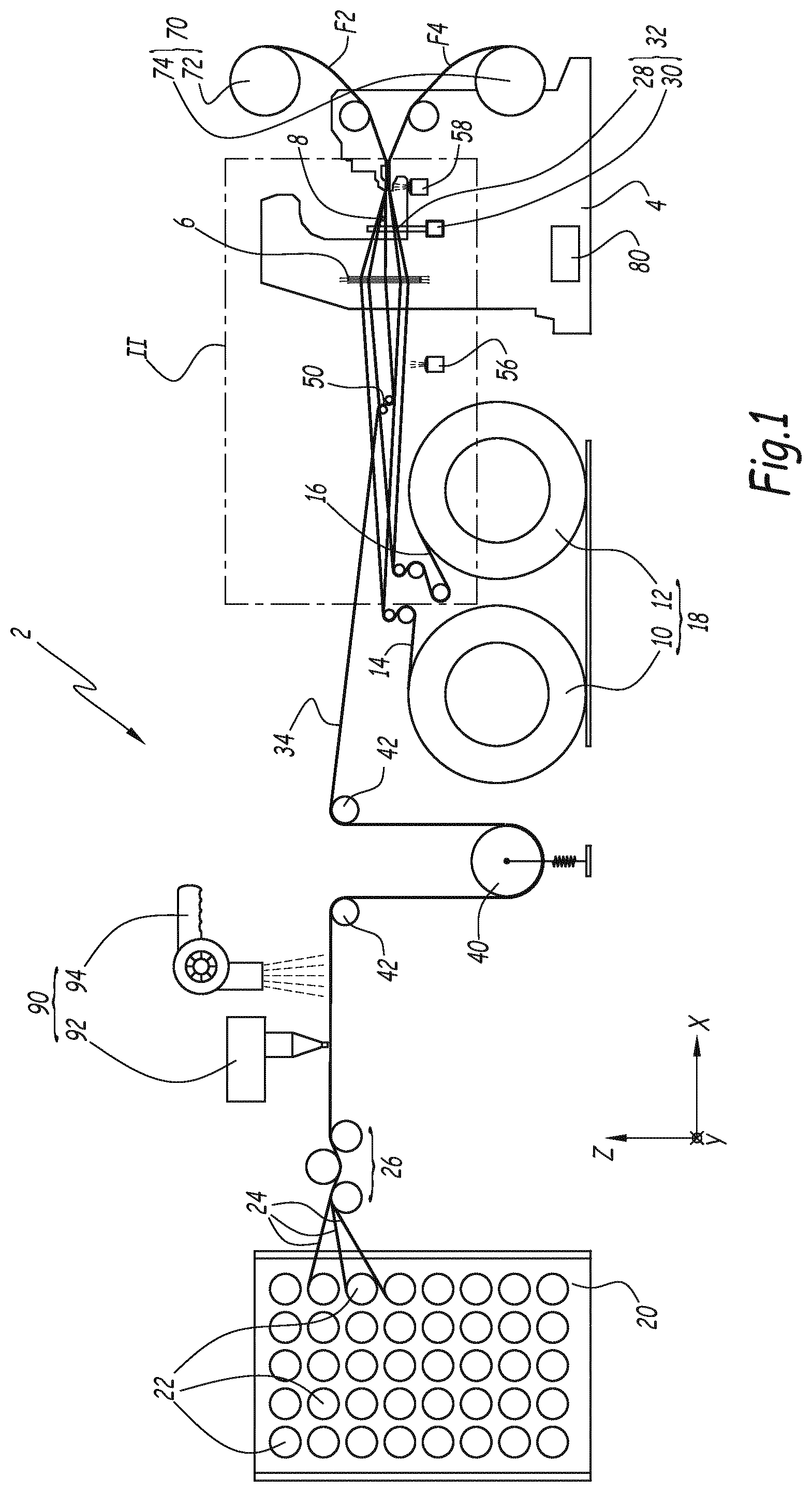
The front side pattern and the back pattern are similar. The invention will be better understood on the basis of the following description of one weaving machine, some weaving methods and some pile fabrics according to its principle, given by way of reference only in relation to the following figures where: The weaving machine 2 represented on The heddles of shedding unit 6 are supposed to vertically move some warp yarns in order to constitute a shed S where a rapier 8 can be reciprocally moved in order to introduce weft yarns to be woven with the warp yarns going through the heddles of shedding unit 6. Rapier 8 belongs to a weft insertion unit for weaving machine 2. Alternatively, two rapiers or more can belong to the weft insertion unit and several sheds can be constituted for the introduction of weft yarns. According to another approach, other weft insertion means than rapiers can be used. One defines a longitudinal axis X of machine 2 as a horizontal axis along which the warp yarns 1 extend in average, prior to entering shedding unit 6. Axis X is oriented in the same direction as the direction of progression of the warp yarns in weaving machine 2. One defines an axis Y which is orthogonal to axis X and horizontal. Weft insertion occurs along axis Y. Axis Y is oriented from the left to the right of the weaving machine when seen from its output side. One defines a vertical axis Z, orthogonal to axis X and Y and oriented upwardly. Weaving machine 2 includes two beam rolls 10 and 12 from which two sets of binding warp yarns 14 and 16 are unwound in order to be fed to weaving loom 4. Beam rolls 10 and 12 together form a binding warp yarn feeding unit 18 for weaving machine 2. Alternatively, the binding warp yarns 14 and 16 could come from the creel so that the creel is a pile and binding warp yarn feeding unit. In such a case, pile yarn feeding unit 20 and binding yarn unit 18 are made by the same part of weaving machine 2. Weaving machine 2 also includes a pile warp yarn feeding unit 20 made of a creel provided with several bobbins 22 equipped with yarns 24 to be used for forming piles or tufts on the top pile fabric F2 and bottom pile fabric F4 woven on weaving machine 2. On Alternatively, several drawing-in units and other types of units can be used with weaving machine 2 like multi-pulley systems conducting the yarns through the unit, gripping rollers, or a transport mechanism units wherein yarn sets can be driven by displaceable rollers which apply an adjusted force by the gravity of a roller, by friction of the rollers, or by varying the feed rate of the yarns through the unit... The number of rollers of such a unit can be equal to 2 or larger than or equal to 4. Weaving machine 2 also includes a reed 28 driven by a sley 30. Items 28 and 30 together form a beating up mechanism 32 for beating the weft yarns into the shed, at a beating point 31. 34 denotes the reference of the warp sheet made by the juxtaposition of pile warp yarns along axis Y between yarn feeder 26 and shedding unit 6. Yarn feeder 26 is designed to provide a uniform or near uniform tension of the warp yarns 24 along the weft of the warp sheet 34, that is along a direction parallel to axis Y. This is obtained thanks to the friction rollers which apply the same stretch on the whole warp yarns unwinding from the creel, along an axis parallel to the weft insertion axis Y. A buffer mechanism 40 is located on the path of warp sheet 34 between yarn feeder 26 and shedding unit 6. Buffer mechanism 40 compensates fluctuations in the progression of the warp sheet, these fluctuations being due to the movements of the heddles of shedding unit 6 and to the movements of reed 28 in weaving loom 4. Buffer mechanism 40 provides a constant warp yarn speed along the path of warp sheet 34. Buffer mechanism is connected to the ECU unit 80 for storing yarn material at a controlled quantity, and at a controlled speed. Alternatively, the buffer mechanism can operate mechanically with elastic means in a passive way, without being actively driven by the ECU. Still alternatively, the treatment unit can anticipate and compensate some fluctuations of the shedding unit by varying the operation sequence: for example while the shedding speed rises, the printing head can apply the ink more quickly or in a shorten sequence, for the warp pile pattern to be respected as the speed of the warp sheet rises, and for the printed pattern to approach the required pattern as much as possible. Alternatively, the adjusting sub-assembly 50 contributes to compensate the yarn speed fluctuations due to shedding and beating-up. Moreover, in the situation of a loom stop, which can occur in case of detection of a yarn breaking, the running of the yarns downstream of the buffer should stop, like the shedding operations stop. Meanwhile, the printing operation can continue for a period needed to end the application of treatment on some warp yarns. Thus time for the printing cycle can be completed. Inversely, in the situation of the loom start, the operations are reversed so that the shedding should start before the printing unit warms up and starts its printing cycles. The start of the printing operations can occur after some preliminary operations, while the loom starts the shedding operations. So, by storing pile warp yarns respectively before or after the mentioned printing operations, the buffer compensates the running of the warp yarns between the printing unit and the shedding unit while their respective yarn running is not the same. In other words, the buffer mechanism 40 stores some pile warp yarns 24 while the treatment unit 90 runs faster than the shedding unit, and it provides some pile yarns while the shedding unit runs faster than the treatment unit. The buffer compensates simultaneously the running of the warp yarns for the top fabric F2 and for the bottom fabric F4. Weaving machine 2 also includes some pulleys 42 which form guiding means for the warp yarns 24 of warp sheet 34. Warp yarns 24 can be guided as a spread sheet under the treatment unit 90. In particular the yarn feeder 26 is provided to apply a uniform tension to the spread sheet along the weft of the warp sheet between the yarn feeder and the pulleys 42, or between the yarn feeder and the buffer mechanism 40. In order to allow application of different colour inks onto two neighbouring pile warp yarns 24, separation means are used for separating the warp yarns from each other. For example a reed can settle the warp yarn gap in a direction parallel to axis Y, at a set distance defined by the teeth module of the reed, which particularly helps the neighbouring warp yarns belonging to two different patterns not to be affected by the wrong colours during the treatment step. Weaving machine 2 also includes at least one adjusting sub-assembly 50 which includes two sets of rollers 52 and 54 interposed on the path of warp sheet 34, between yarn feeder 26 and shedding unit 6. The location of rollers 52 and 54 along this path may be adjusted via non-represented electric motors, in particular in rotation around an imaginary axis parallel to axis Y and located between rollers 52 and 54, as shown by arrow A50. Also, the path of the warp yarns between the two rollers can be varied. Thus, adjusting sub-assembly 50 allows changing the length of the path of warp sheet 34 between yarn feeder 26 and shedding unit 6, which has an influence on the speed, feed rate and/or tension of the warp yarns 24 downstream of adjusting sub-assembly 50 and upstream of beating point 31. Adjusting sub-assembly 50 can be controlled by ECU 80 to slacken or stretch the pile warp yarns 24 during at least one pick of the shedding unit 6 in order to relocate a transition zone with respect to the inserted weft yarns. By downstream, one means “after adjusting sub-assembly 50” in the direction of movement of pile yarns 24. This definition of “downstream” applies mutatis mutandis to all other occurrences of this word. Upstream should be understood as opposite to downstream in the direction of movement of pile yarns 24. Alternatively, the path of the pile warp yarns 24 may remain the same and adjusting sub-assembly 50 varies a friction effort applied by rollers 52 and 54. This may occur by installing these rollers in contact with each other and by varying a contact force between these rollers. Alternatively or in addition, the adjusting sub-assembly 50 can include individual actuators driving individual heddles for deviating pile warp yarns from their normal path, which also allows adjusting the path length, thus the speed and/or tension of the warp yarns downstream of yarn feeder 26. Such individual actuators might be similar to the ones disclosed in EP-A-1 069 218 or EP-A-1 491 669. Adjusting sub-assembly 50 also includes two cameras 56 and 58 which are respectively located and oriented in order to take pictures of the warp shed 34 and of at least one of the two fabrics F2 and F4, near the beating point. In the example of the figures, camera 64 takes photos of the back side of fabric F4. Alternatively, one or several other cameras can be used to take photos of the back side of fabric F2 and/or the front sides of the fabrics, or a scanner moving along an axis parallel to Y. Alternatively, one or several optical sensors or cameras of the adjusting sub-assembly 50 can be set on the path of warp sheet 34, between yarn feeder 26 and shedding unit 6 of the weaving machine 2. For example a sensor can be settled on the treatment unit 92 in order to monitor the printing sequence, the printed pattern and/or any yarn breakage of the pile yarns. The adjusting sub-assembly 50 operates simultaneously for monitoring and adjusting the patterns of the warp yarns for the top fabric F2 and for the bottom fabric F4. Weaving machine 2 also includes a take up system 70 which comprises two beams 72 and 74 for winding fabrics F2 and F4 on the outlet side of weaving machine 2. These beams 72 and 74 are driven by non-represented electric motors. Weaving machine 2 also includes an electronic control unit or ECU 80 which is capable of piloting most components of weaving machine 2 and synchronize them. As shown on As shown on Alternatively, one or more buffers could be used along the path of the pile warp yarns to compensate the tension fluctuations. Alternatively the drawing-in unit 26, the buffer 40, and/or the adjusting sub-assembly 50 might be combined in a non-represented multifunctional unit which can operate one or several of the respective drawing-in, compensating and adjusting operations of the weaving machine. Weaving machine 2 also includes a treatment unit 90 which might be so-called “yarn treatment unit” and which is located, along the path of the warp yarns 24 and warp sheet 34, between yarn feeder 26 and shedding unit 6, as shown on Preferably, the printer 92 is an ink jet printer or a printer delivering droplets of ink on pile warp yarns 24 by gravity and electromagnetically controlled. According to an optional aspect of the invention which is not represented, treatment unit 90 can also include a pre-treatment device located upstream of printer 92, in order to prepare the warp yarns 24 before printing, so as to improve the fixation of ink onto the warp yarns 24. For instance, this pre-treatment device can incorporate another dryer, or a chemical applicator for changing the PH of the yarns, or for changing the viscosity of the ink delivered by the treatment unit. Alternatively, the non-represented pre-treatment device or the fixing unit 94 can include a steamer, heat rollers, microwave generator, a ultraviolet generator . . . applying on pile warp yarns any operations associated to the ones performed by the printer unit 92. Alternatively, the pre-treatment device and/or the fixing unit 94 can be part of the treatment unit 90. As shown on As visible on Alternatively individual or mutual control units might control the components of the yarn treatment unit 90 and the components of the loom system represented on The structure of weaving machine 2 explained here-above allows applying on warp yarns 24, coming out of yarn feeder 26, some segments of differently coloured inks, in order to obtain pile tufts of different colours, in directions parallel to axes X and Y, in fabrics F2 and F4. More precisely, as shown on Pile warp yarn 24 Thus, when pile yarns 24 Top pile fabric F2 is made by the upper part of the yarns represented on the left of Similarly, bottom pile fabric F4 includes a backing fabric BF4 made of binding warp yarns 14 and 16, weft yarns 36 and tuft burls. Bottom pile fabric F4 also includes a tuft portion T4 which extends away from backing fabric BF4, on the front side of bottom pile fabric F4. The binding warp yarns might also be so-called “ground warp yarns” like the backing fabric might also be so-called “ground fabric”. The succession of segments S241 to S252, and so, on pile warp yarn 24 In each pile fabric F2 of F4, a tuft includes two legs which extend mainly from the backing fabric and a burl portion which turns around a corresponding weft yarn 36 and whose ends can extend slightly out of the backing fabric. The fabric has double legged tufts. The burl portion can be read as the pile portion turning around the weft yarn 36 with the toe portions of the pile legs of the same colour which can slightly extend out of the backing fabric at the bottom of the pile legs. In other words, if one considers a transition zone between a burl segment and a pile leg segment, this zone may be out of the backing fabric along the pile leg portion. The burl portion and the transition zones should not be visible from the pile side of the final fabric unless the fabric is manipulated and the tufts are handled by separating the pile legs. As shown on The pile repartition represented on the left of The right part of As can be deduced from the comparison of Similarly, On the other hand, the cut piles of fabric F2 form, with their portions corresponding to picks I to VII, a horizontal portion of a grey triangle bordered by a black contour, which belongs to a pattern P2′ to be made on the front side of fabric F2. One understands that another pattern is created on the front side of pile fabric F4 by the tuft portion T4 when seen in the direction of arrow A4′. This other pattern does not need to the symmetric from pattern P2′ Thus, by applying printed patterns P24 Moreover, since a pile warp yarn can be used for forming tufts of different colours, the pile warp yarn consumption can be decreased as compared to prior art approaches. Since no pile warp yarns has to be buried as dead yarn in the backing fabric, the binding structure can be simplified, which also slightly decreases the binding warp yarn consumption. From a process point of view, when final patterns P2, P2′, P4 and equivalent have been designed, they can be provided to ECU 80 via interface 82 or uploaded from memory 84. It is then possible for a microprocessor of electronic control unit 80 to compute the printed pattern P24 On this occasion, one can make a difference between the pile segments of each printed pattern P24 For instance, one can identify segment S242, S246, S248 and S252 as dedicated to pile pattern P2′. The same applies for segments S243′, S245′, S249′, S251′. Similarly, segments S243, S245, S249, S251, S242′, S246′, S248′ and 252 can be identified as dedicated to the pile pattern in pattern fabric F4. Similarly, segments S241, S247, S244′, S250′ can be identified as dedicated to the back side pattern P2 of the top pile fabric F2, whereas segments S244, S250, S241′ and S247′ can be identified as dedicated to the back side pattern P4 of bottom pile fabric F4. The camera 58 can monitor an offset or a elongation of the segments or an offset of the transition zones; an offset is visible, along an axis parallel to the weft insertion axis Y, for all the pile warp yarns. Detection of such an offset or an elongation should induce adjustment of the tension of all the pile warp yarns 24 to come back to the normal situation. Four colours are used in printed pattern P24, namely black on segments S241, S244, S250 and so on, yellow represented with hatchings in a first direction in segments S242, S243 etc. . . . , green represented with hatchings in a second direction in segments S245 and S246 and blue represented with crossed hatchings in segments S248 and S249. In practice, and in order to avoid colour mixing between segments of pile legs having different colours in the two-pile fabrics, like segments S242 and S243 or S242′ and S243′ in the example of As shown on Actually, such an offset configuration can be detected by cameras 56 and 58 either prior to or after weaving. In particular, if camera 58 is located above pile fabrics F2, it allows detecting an offset and some errors in the back pattern P2. The information sent by cameras 56 and 58 is provided to control unit 80 which can compare it to the required final pattern stored in memory 84 and, in case of an offset, send a warning message via interface 82 and take proper measures by adjusting the path of the warp sheet 34 thanks to a movement of rollers 52 and 54 in the direction of arrow A50 or by changing the distance between these two rollers. This allows modifying the path of the warp yarns realigning printed pattern P24 on the picks, in order to come back to the normal situation represented on In practice, control unit 80 does not wait for the situation to be as bad as the one represented on The operation of rollers 52 and 54 allows varying the tension of the warp sheet 34. If individual actuators are used as considered in variant here-above, it is also possible to vary the path and the tension of one or several of the warp yarns. According to another approach, adjustment of the printed pattern might occur by incorporating at least one pile warp yarn into a backing fabric BF2 or BF4 for one or several picks. This allows changing the visible parts of the corresponding yarn or yarns 24. According to an alternative approach, the adjusting step can be implemented by modifying a vertical distance A between the two pile fabrics during weaving, this distance A being defined between the centers of two weft yarns 36 belonging respectively to backing fabric BF2 and backing fabric BF4. This allows changing the zone of pile warp yarn 24 forming a burl and the length of the tuft legs, thus the point at which they are cut along line L. As shown on This modification of the vertical distance between the pile fabrics can also be obtained with lancets having a wedge shape. These lancets are more or less introduced within the shed along axis Y, according to the needs. Alternatively, the height of the pile legs is set by a cloth table or pile rail. The height of the cloth table or pile rail can be adjusted with a complementary non-represented adjusting unit like adjustable pistons of motorized endless screws connected to the cloth table to modify the vertical distance between the two fabrics in the process of being woven, thus the pile height. According to another approach, it is also possible to modify printed pattern P24 by varying the operation sequence of printed head 92. In other words, it is possible to adjust the length and the position of the printed segments S241 to S252 in order to take into account the actual pattern obtained on the pile fabrics F2 and F4. For example, if the adjusting sub-assembly unit 50 detects a trend of offset like the transition zones of one or several pile warp yarn migrate backward or forward compared to the transition zones of the other pile yarns, and in the two final fabrics, then the print head 92 can be instructed to print differently. The length and the position of some printed segments or the position of these segments along the pile can be modified. In other words the treatment unit can be instructed by ECU 80, in a closed loop control process, to change the operation sequence and to adapt the printed patterns as a function of the monitored defaults on the final fabrics, so as to print and obtain corrected patterns in the fabrics which correspond to the patterns required by the weaver. The alternative method is represented on According to this method, the adjusting sub-assembly 50 can monitor the segments of the sheet 34 of warp yarns and particularly the segments of the warp yarn 24. A non-represented camera is arranged on the exit side of the treatment unit 90 , for instance just behind the printing unit 92 visible on In the normal configuration represented for warp yarn 24 on The ECU 80 analyzes the color, location and length of each segment, on the basis of the images received from the camera. In particular, for each segment the location of its transition points is compared in sequence to the required transition point locations of the segments in a data set defining the pattern to be realized. The same applies for the color of each segment and its length. In the default situation represented by pattern P24′, after monitoring and taking pictures of segment S250, the camera takes a picture of segment BS251, which corresponds to the beginning of segment S251 In the normal situation, and of faulty segment F271. The camera transmits these pictures to the ECU 80. This applies also for the successive segments S251 to S260 In such a case, ECU 80 detects that:
These incorrect segments and this offset implies local and permanent defaults in the aspect of the woven and final pile pattern as visible on the right side of In particular, the ECU 80 compares these segments to the required segments and controls “in real time” the treatment unit 90, while the process of weaving is running, to adjust the process of printing the segments as quickly as possible. In such a situation the ECU 80 drives the offset of the full pattern P24′ whose printing will be anticipated on the time scale. In the same time, the ECU 80 can compute that a mechanical correction cannot be enough to shift the sequence, provided it is a general shift of the pattern on the warp sheet. In such a case, the approach of Thus, in such a case, after applying successive segments S251 to S256 on warp yarn 24′, that as quickly as possible after the default segment F271 has been detected, the printing sequence is adjusted and the treatment unit 90 is driven to shift its sequence earlier/backward so that:
Thanks to this adjustment step of the weaving machine, the warp yarn 24′ will be woven within the top and the bottom pile fabrics F2 and F4 around weft yarns 36 as illustrated on Advantageously, for all the above-mentioned methods, the segments of the warp yarns for the top fabric F2 and for the bottom fabric F4 are simultaneously monitored, and the possible adjusting operations can be controlled simultaneously by ECU 80 which manage the production of the two fabrics from the required pile patterns. According to the type and the scale of detected defaults, the weaving machine drives the adjusting steps at the treatment unit 90, at the buffer mechanism 40, . . . or/and at the shedding unit 6 with a preset priority ranking, and synchronizes its machine components accordingly. In the examples of In a variant, one of the binding warp yarns might be straight and form a reinforcing yarn or filling yarn for the corresponding backing fabric. One considers the tuft 1024formed in top pile fabric F2 at pick IV. This tuft includes two legs 1022 and 1024 and one burl 1026 respectively formed by segments S249′, S251′ and S250′ of pile warp yarn 24 The transition between the colours of burls 1026 and legs 1022 and 1024 is not systematically sharp but may be progressive with a colour gradient, as represented by the transition zones Z1 and Z2 between segments S242 and S243 and between segments S242′ and S243′ for tufts 1022and 1042on Alternatively, the transition zone between the pile top of the tufts and the pile burl can be made of some successive intermediate segments of colour. The transition zones are located at the ends of the burl segments and at the ends of the pile leg segments. The transitions zones between a pile segment and a burl segment are located preferably all at the same height of the fabric, more preferably in the backing fabric BF2 or BF4. Most preferably, the transition zones of a tuft are located symmetrically at the same height of the fabric. Advantageously, monitoring the height of the transition zones in the backing fabric BF2 or BF4 makes the offset of segments easier to adjust, and the process of adjusting easier to manage for the whole fabric. Pile tufts 1024, 1025and 1026turn around weft yarns 364, 365and 366of top pile fabric F2 which are consecutive, that is which follow each other in backing fabric F2 along the warp direction. Pile tufts 1027, 1028and 1029have black legs 1022 and 1024 whereas tufts 1024, 1025and 1026have grey legs. Tufts 1024, 1025, 1026and 1029have white burls, whereas tufts 1027and 1028have black burls. All the tufts 102, and 104, represented on Once cut along an horizontal line L, or more preferably along one of two parallel horizontal lines L2 and L4 as explained here-above in conjunction with In such a fabric F2, it is possible to have different colours for a pile pattern visible from the front side of the fabric and for a pile pattern visible from the back side of the fabric, without needing to incorporate dead pile yarns into the backing fabric. As shown for pile warp yarn 24 Consider, for instance, pile tuft 1022and 1023which are consecutive in pile fabric F2. Pile tuft 1022includes three segments S243′, S244′ and S245′ with different colours. Such is also the case for pile tuft 1023, with segments S246, S247 and S248. Actually, these tufts can be provided with only two segments of different colours. Moreover, segments S244′ and S247, which respectively correspond to the pile burl portions of pile tufts 1022and 1023, have two different colours. The same comments apply to other consecutive pile tufts in the two respective pile fabrics F2 and F4, including at the level of the W weave at picks XI-XIII in pile fabric F4. According to an important aspect of the invention, the colour segments respectively applied on warp yarns 24 vary along the width of the two pile fabrics F2 and F4, that is in a direction parallel to axis Y. Treatment unit 90 is configured for this. For instance, printing head 92 can be mounted on a carriage which is movable parallel to axis Y and the working operation instructions sent by ECU 80 to printing head 92 may vary according to the position of this printing head along axis Y. Other approaches can be implemented, in particular if printed head extends on the whole width of weaving machine 2. In such a case, printing head has a number of outlet orifices corresponding to the number of pile warp yarns to be dyed and the flow of ink coming out of each of these openings is controlled individually. According to a non-represented aspect of the invention, it might be relevant to print some warp yarns downstream of treatment unit 90. A movable printing unit can be used for this purpose. In particular, a second printing head can be installed close to shedding unit 6, in order to print or reprint colour segments where appropriate, in particular when a correction is needed. As shown on In the example of With such a binding structure, a high density can be obtained warpwise, so that several pile leg segments will have to be coloured similarly in order to produce a pattern point in the final requested printed pattern P2′ and equivalent on the front face of the fabrics F2 and F4. In other words, the segments of printed patterns P24 Furthermore and advantageously, with such binding structures for high density, it becomes possible for the weaver to print patterns more finely, in order to obtain fabrics representing a drawing with high definition. In the example of In the example of The structures represented on In the example of In the example of According to a non-represented aspect of the invention, different kinds of binding structures can be used in the same pile fabric. On Coming back now to the computation of the printed patterns P24 Alternatively, the required final patterns can be extracted from a program of a traditional carpet system whose instructions are related to the motion of pre-dyed warp yarns in the patterning shedding machine. These instructions can be computed and transformed by the ECU 80 in data for the weaving machine 2. In other words, a numeric discretization of the final pattern is implemented. The definition of the discretization of the final pattern can be high since a colour can be assigned to each pile leg. Thus, for a fabric with several millions of legs per m2, the invention allows weaving an image with several millions of pattern points per m2. Once the final pile pattern has been discretized, as explained here-above, a computation takes place for each pile warp yarn 24j, with j between 1 and N′, j being the number of pile warp yarns along the Y axis, in order to transform the local positions of each point (Xi, YJ, colour) of the final pattern along axis X in the finished fabrics into a local position for a corresponding segment along the corresponding pile warp yarn 24jof the corresponding yarn set. For Alternatively, treatment products of some premixed-colours can be used, like premixed green and brown inks for producing fabrics made of green and brown patterns. Each printed pattern 24jincludes, for each segment S241, S242, . . . , S241′, S242′, . . . , its starting point and its end point, together with the corresponding colour to be printed on the corresponding warp yarn 24j. The algorithm can also set an origin starting point t0which will define the origin of all printed patterns 24j. In other words, each segment of colour printed on one pile warp yarn 24jis defined by the following data: (j, Lij1, Lij2, CMYK) where:
In practice, when all segments are consecutive one after the other, with no unprinted space, one has the following relationship Lij2=Li+1j1. Actually the conversion algorithm which converts the discretized final pattern (Xi, Yj, colour) into the respective printed patterns (j, Lij1, Lij2, CMYK) will take into account at least some of the following parameters,
As explained here-above in conjunction with The algorithm also takes into account the shearing process which occurs after separation of the two fabrics F2 and F4 out of the weaving machine 20 during the offline process. This shearing process must give a uniform pile leg height and may take place along two parallel lines, as mentioned here-above with respect to Once the pattern P24ito be printed on each pile warp yarn 24jhas been determined by the algorithm, this data is used by electronic control unit 80 in order to generate a spread sheet which is stored in memory 84 and which includes data in the form (j, tij, lij, CMYK) where:
For instance, for warp yarn number 893, if a black segment is to be applied 20 seconds after start, on five millimeters, the corresponding data set will be: (893, 20, 5, black). When colours are applied along each yarn 24 at preset spaced position according to the corresponding printed pattern P24i, they will penetrate in the fiber of the corresponding warp yarn 24jand will dye it. The successive transition line between the respective segments S241, S242 . . . S241′, S242′ . . . of the respective warp yarns 24 are set considering the length of each segment to dye before weaving. Since, as mentioned here-above, the drawing in unit formed by yarn feeder 26 provides a uniform tension of the pile warp yarns 24 along the width of the warp sheet 34, printer 92 prints colour segments on pile warp yarn segments having the same tension, which favours parallel running of the pile yarns between yarn feeder 26 and shedding unit 6 and simultaneous arrival of all segments of the printed patterns P24jdevoted to one pick. Progression of the respective pile warp yarns 24 and binding warp yarns 14 and 16 toward shedding unit 6 is not continuous, but may take place by successive strokes, due to the shed opening and to the movement of the reed 28. Under such circumstances, printing can occur in successive steps during a stop or down time of the pile warp yarns 24 in their progression towards shedding unit 6. According to an aspect of the invention which is represented on Such graduation marks are, in particular, useful when one yarn is printed in one colour on a long distance corresponding to a large number of segments, e.g. in red. The black rings allow detecting the actual position of the corresponding printed pattern. These graduations marks are also useful while producing carpets whose front side and back side patterns are the same. It makes possible for the adjusting unit to monitor better the lengths of segments of the pile warp yarns. Thus, locating the graduation marks M24 and M24′ along a given pile warp yarn 24 allows efficiently using the adjusting sub-assembly 50 of weaving machine 2. Provided the transition marks of consecutive tufts have similar locations, they are at the same height in the fabric Alternatively the graduation marks can be any other colour than black, or be unprinted rings on the pile yarns which can be monitored and identified by the adjusting sub-assembly 50. Alternatively the graduation marks can be produced with an invisible ink like fluorescent ink whose spectrum is not perceived by human, but can be detected and monitored by a UV camera belonging to the adjusting sub-assembly 50. The HMI 82 reports information to the weaver with respect to the on-going weaving process and allows the weaver to change optionally some parameters of the weaving process as needed, for instance the pile height or the shearing margin distance d. This interface 82 also allows monitoring of the printer 92 and of the weaving loom 4. It can also provide information regarding the printing process of the pile warp yarns, in particular:
This data displayed or edited on interface 82 can also be taken into account by electronic control unit 80 in order to optimize the printing operations, while taking into account the requested pattern. It makes possible for the weaver to adjust manually the process through the HMI interface 82, for example with a correction factor related to the application or to the article. The invention is represented on the figures in case the pile warp yarns 24 alternate between the top and bottom fabrics F2 and F4 and a step is provided for separating these two fabrics by cutting the pile warp yarns with a non-represented cutting unit in order to create double legged tufts 102i, 104i. However, according to a non-represented embodiment of the invention, some or the totality of the fabrics can be provided with pile warp yarns which form loops around some weft yarns inserted in the shed outside a backing fabric. This enables having a bouclé effect or a fabric with ribs. For such fabrics, one can consider loop segments along the loops visible on the front side of the fabric, with the consecutive burl segments visible on the back side of the fabric. A first pattern is visible on the front side of the fabric, and a second pattern is visible on the back side. Thanks to the invention, this second pattern can potentially be different from the first pattern. It should be understood that the loop segments of bouclé carpet do not form double legged tufts, but they are quite similar to pile segments of cut pile carpets for creating a printed design and for the invention. One can consider that the pile loop portions on the front side of a bouclé carpet are comparable to parallel tufts in the width of the carpet, each tuft being made of a burl and two pile leg portions, these two legs being respectively joined with a previous tuft leg and a next tuft leg belonging to respective previous and next tufts of the same warp yarn. These legs form external loops on the front side of the fabric by surrounding the weft yarn externally of the backing fabric; they are not cut, besides the pile burls on the backside of the backing fabric weft yarns. Due to the great versatility of the method of the invention according to which each pile warp yarn can be dyed with a corresponding colour, it is possible to weave a pile yarn fabric with tufts 102i, 104idisplaying more than 16 different colours with a pile density preferably over 300 000 piles per m2more preferably over 500 000 piles per m2, most preferably over 1 000 000 piles per m2. Actually, the number of displayed colours can be more than 32, preferably more than 64. Thanks to the invention, the design required for a pile fabric on its front side and/or on its back side can be sharp, without mixed contours, while being obtained with a simple and repetitive binding structure, whose arrangement is more predictable than traditional patterned carpets. Thanks to the invention the local treatment of segments on the pile warp yarns offer unlimited possibilities to produce countless patterns of carpets on its two sides. Moreover, the invention allows changing the pattern and the binding structure of pile fabrics F2 and F4 produced on weaving machine 2, without losing a substantial amount of material and without spending a lot of time to settle the weaving machine, since the main operation is to use the algorithm to compute the respective printed patterns P24 Advantageously, pile warp yarns 24, and possibly binding warp yarns 14 and 16 are uncoloured and white. This is easier to manage for the weaver and facilitates maintenance of the weaving machine 2. Moreover, the bobbins 22 can be set head to tail, in order to avoid a stop of the loom work. Preferably the ends of the bobbins are connected by splicing and use so-called “spliced yarns”. The fact that the creel 20 is simpler than in known weaving machines improves its reliability and lowers the number of pile breakages due to less frictions between pile yarns and less angular means for guiding the yarns. Moreover, the simpler structure of the creel provides a more balanced weaving sequence and less tension in the warp sheet. According to another aspect of the invention, it is possible to couple the above-identified method with a traditional process including pre-coloured pile warp yarns. Then, some pile warp yarns will be used as delivered by some bobbins and the other pile warp yarns will be printed on demand as explained here-above. Pile warp yarns can be made of Polyamid or Polyester material. Moreover, some of the warp yarns, like ground warp yarns and some pile warp yarns on the side of the carpet can be woven without being printed. According to another aspect of the invention, long pile fabrics or shaggy carpets can be obtained with the invention. The invention offers the possibility for such fabrics to disclose long piles or long loops with different colours. Alternatively, a random mode can be selected for printer 92, which induces a randomly applied printed pattern on the pile warp yarns 24. According to another approach, large areas of randomly applied colours can be generated on the pile fabrics F2 and F4. They will look like “patches” on the final product. Alternatively, the transitions zones between a pile segment and a burl segment are located on the backside of the fabric, or on the pile side of the fabric. According to a non-represented alternative embodiment of the invention, the colour printed in some of the segments can be variable along the length of these segments which are due to form pile legs, like pile legs 1022 and 1024 identified here-above. In such a case, these segments are dyed while taking into account several superposed patterns. One obtains a carpet with different patterns defined in the depth of the pile layer. After successive shearing operations, the carpet design can be changed due to the different patterns disclosed by the top of the piles. The invention is not limited to the case where the different products applied on the warp yarns are inks. The local treatment applied by the treatment unit 90 may consist in applying other types of products, such a chemical agents including acid or chlorine. The local treatment performed by unit 90 may, instead of applying a product, consist in submitting the warp yarns to heating/burning, an UV light, microwaves or an electric current. Alternatively, a supplementary and dedicated treatment unit could apply segments on the binding yarns or/and on the weft yarns. Several of the treatments mentioned here-above can be combined. Each pile fabric F2 or F4 presents one or several pile patterns P2, P2′, P4, . . . According to another aspect of the invention, a complementary treatment may occur during a finishing operation, after weaving, in order to improve or reveal some pattern segments. The invention is represented on the figures in case weaving machine 2 makes use of a single warp sheet 34 for all the pile yarns. Alternatively, several warp sheets can be used by superposing or setting aside several groups of pile yarns for independent treatment between the feeding units and the shedding unit. This can be operated by several treatment units. The embodiments and/or variants considered here-above can be combined in order to generate new embodiments of the invention, is the framework of the attached set of claims. This weaving machine (2) is for simultaneously weaving a top pile fabric (F2) and a bottom pile fabric (F4), each pile fabric presenting some pile patterns (P2, P2′, P4) and including tufts, made from warp yarns (24), binding warp yarns (14, 16) and inwoven weft yarns. This machine comprises a pile warp yarns feeding unit (20), a binding warp yarns feeding unit (18), a shedding unit (6) for creating a shed with the pile warp yarns and the binding warp yarns (14, 16). A weft insertion unit (8) is used for inserting the weft yarns in the shed in successive insertion cycles. A beating-up mechanism (32) is used for beating the weft yarns into the shed. A take up system (70) is used for taking-up the two pile fabrics. A drawing-in unit (26) draws the pile warp yarns from the pile warp yarn unit (20) and a control unit (80) controls operation of the weaving machine (2). This weaving machine also comprises a treatment unit (90) located, along a path of the pile warp yarns (24), between the pile warp yarns feeding unit (26) and the shedding unit (6), for applying different segments of treatment on at least some of the pile warp yarns (24). 1.-32. (canceled) 33. Weaving machine for simultaneously weaving a top pile fabric and a bottom pile fabric, each pile fabric presenting one or several pile patterns and including tufts, made from pile warp yarns, binding warp yarns and weft yarns, the machine comprising
a pile warp yarns feeding unit, a binding warp yarns feeding unit, a shedding unit for creating a shed with the pile warp yarns and the binding warp yarns, a weft insertion unit for inserting the weft yarns in the shed, in successive insertion cycles, a beating-up mechanism for beating the weft yarns into the shed, a take up system for taking-up the two pile fabrics and a control unit for controlling operation of the weaving machine, characterized in that the weaving machine also comprises a treatment unit located, along a path of the pile warp yarns, between the pile warp yarns feeding unit and the shedding unit, for applying different segments of treatment on at least some of the pile warp yarns. 34. A weaving machine according to 35. A weaving machine according to 36. A weaving machine according to 37. A weaving machine according to 38. A weaving machine according to 39. A weaving machine according to 40. A weaving machine according to 41. A weaving machine according to 42. A weaving machine according to 43. A weaving machine according to 44. Method for simultaneously weaving a top pile fabric and a bottom pile fabric each fabric presenting pile printed patterns and including
tufts, made from pile warp yarns, binding warp yarns and weft yarns, this method taking place on a face-to-face weaving machine which comprises:
a pile warp yarn feeding unit, a binding warp yarns feeding unit, a shedding unit for creating a shed with the pile warp yarns and the binding warp yarns, a weft insertion unit for inserting the weft yarns in the shed in successive insertion cycles, a beating-up mechanism for beating-up the weft yarns into the shed, a take-up system for taking-up the two pile fabrics, a drawing-in unit for drawing the pile warp yarns from the pile warp yarn unit and a control unit for controlling the weaving machine characterized in that the method includes at least the following steps: a) presenting the pile warp yarns to a treatment unit located, along a path of the pile warp yarns, between the pile warp yarns feeding unit and the shedding unit, b) applying, with the treatment unit, different segments of treatment on at least some of the pile warp yarns, c) weaving the treated pile warp yarns into the two pile fabrics. 45. A method according to 46. A method according to aa) determining the printed yarn pattern from the final pile pattern of each woven fabric. 47. A method according to 48. A method according to 49. A method according to d1) a picture of at least one pile fabric and/or a picture of the warp sheet is taken and this picture is transferred to a control unit of the weaving machine which computes the position and/or length of the segments of treatment along each corresponding pile warp yarn. 50. A method according to d2) varying the tension and/or yarn feed rate of at least one pile warp yarn, d3) incorporating at least one pile warp yarn into a backing fabric as a dead pile yarn, for one or several picks, d4) modifying a vertical distance between the two pile fabrics or d5) varying the operation sequence of the treatment unit on at least one pile warp yarn, as a function of the actual position of a previously applied segment on the same pile warp yarn. 51. A method according to e) separating the top and bottom fabrics by cutting the pile warp yarns in order to create double legged tufts. 52. A method according to 53. A method according to 54. Pile fabric presenting a pile pattern on one at least side, this fabric including:
a backing fabric woven with yarn sets including :
at least two binding warp yarns and weft yarns and pile tufts
interlaced in the backing fabric, belonging to a yarn set, and each forming two pile leg portions on a front side of a backing fabric, and at least a pile burl portion on a back side of the backing fabric, characterized in that for a first pile tuft and a second pile tuft consecutive in a warp direction in a yarn set, at least one of the first and second consecutive tufts includes two segments with different colours on the same tuft, and the pile burl portion of the first tuft discloses a segment of a first colour and the pile burl portion of the second tuft discloses a segment of a second colour, different from the first colour. 55. A pile yarn fabric according to 56. A pile yarn fabric according to 57. A pile yarn fabric according to 58. A pile fabric according to 59. A pile yarn fabric according to 60. A pile yarn fabric according to 61. A pile yarn fabric according to 62. A pile yarn fabric according to 63. A pile fabric according to 64. A pile fabric according to
According to the invention, the weaving machine also comprises a treatment unit located, along a path of the pile warp yarns, between the pile warp yarns feeding unit and the shedding unit, for applying different segments of treatment on at least some of the pile warp yarns.