CHEMICAL SENSOR MODULE AND METHOD FOR IDENTIFYING SAMPLE SUBSTANCES
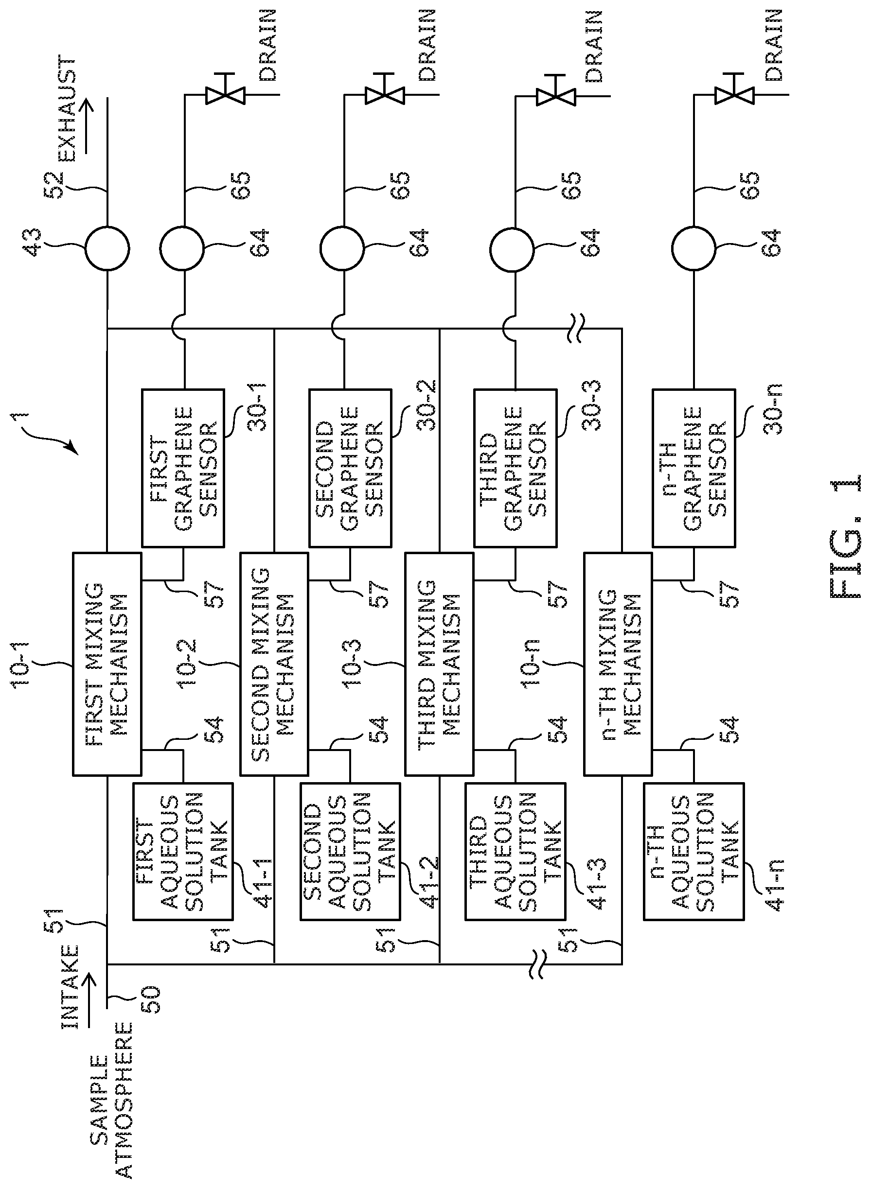
This application is based upon and claims the benefit of priority from Japanese Patent Application No. 2021-048070, filed on Mar. 23, 2021; the entire contents of which are incorporated herein by reference. Embodiments described herein relate generally to a chemical sensor module and a method for identifying sample substances. Graphene exhibits a large change in electrical characteristics (high sensitivity) with respect to the bonding, adsorption, or proximity of atoms and molecules on the surface thereof. A sensor using graphene can be used when detecting a sample substance incorporated into an aqueous solution from the gas phase in the aqueous solution. According to one embodiment, a chemical sensor module includes first to n-th (n is a natural number of 2 or greater) graphene sensors; and an exposure mechanism exposing the first to n-th graphene sensors to first to n-th aqueous solutions containing a sample substance and having different concentrations of phosphate ion, magnesium ion, or sulfate ion. The chemical sensor module identifies the sample substance from the difference in electrical characteristics of the first to n-th graphene sensors. Embodiments will now be described with reference to the drawings. The same components in the drawings are marked with the same reference numerals. The chemical sensor module of the embodiment includes first to n-th (n is a natural number of 2 or greater) mixing mechanisms 10-1 to 10- First to n-th pipes 51 are connected in parallel between an intake pipe 50 and an exhaust pipe 52. Any one of the first to n-th mixing mechanisms 10-1 to 10- Any one of the first to n-th aqueous solution tanks 41-1 to 41- Each of the mixing mechanisms 10-1 to 10- Each of the graphene sensors 30-1 to 30- The first mixing mechanism (hereinafter, also simply referred to as a mixing mechanism) 10-1 includes a mixing tank for bubbling the sample atmosphere into an aqueous solution 100. The mixing tank 11 is connected to the first aqueous solution tank (hereinafter, also simply referred to as an aqueous solution tank) 41-1 via the pipe 54. A pump 12 and a valve 71 are connected to the pipe 54. By opening the valve 71 and driving the pump 12, the aqueous solution 100 stored in the aqueous solution tank 41-1 is supplied into the mixing tank 11. At one end of the intake pipe 50, an atmosphere collection port 50 The mixing tank 11 is connected to the first graphene sensor (hereinafter, also simply referred to as a graphene sensor) 30-1 via the pipe 57. A valve 72 and a pump 13 are connected to the pipe 57. By opening the valve 72 and driving the pump 13, the aqueous solution 100 in the mixing tank 11 is supplied to the graphene sensor 30-1. This mixing mechanism includes the flow path chip 111, a lid 112 superposed on the flow path chip 111, and a porous membrane 121 disposed between the flow path chip 111 and the lid 112. Further, as shown in If necessary, unevenness can be formed on the bottom surface of the groove 117. As the shape of the unevenness, for example, an asymmetric V-shaped groove called a chaotic mixer can be formed. By forming such unevenness, agitation occurs in the microchannel which tends to generate a laminar flow, and the efficiency of taking in target molecules via the porous membrane 121 described later is improved. The porous membrane 121 covers the groove 117. The lid 112 is disposed on the porous membrane 121. The lid 112 is in close contact with the porous membrane 121 via a sealing member (for example, a rubber member) 122. A groove 118 is formed on the surface of the lid 112 facing the porous membrane 121 in the same pattern as the groove 117. The lid 112 is formed with an intake passage 115 connected to one end of the groove 118 and an exhaust passage 116 connected to the other end of the groove 118. The intake passage 115 is connected to the pipe 51 for taking in the sample atmosphere, and the exhaust passage 116 is connected to the exhaust pipe 52. By opening the valve 71 and the valve 72, respectively, and driving the pump 12 and the pump 13, the aqueous solution 100 stored in the aqueous solution tank 41-1 is supplied from the liquid inflow path 113 to the groove 117. The aqueous solution 100 does not permeate the porous membrane 121. Therefore, the aqueous solution 100 does not flow into the groove 118 above the porous membrane 121. In addition, only one of the pump 12 and the pump 13 may be used. By driving the intake and exhaust device 43 connected to the exhaust pipe 52, the sample atmosphere taken into the pipes 50 and 51 from the atmosphere collection port 50 The aqueous solution in the groove 117 exposed to the sample atmosphere flows through the liquid outflow path 114 as it is and is supplied to the graphene sensor 30-1. The graphene sensor 30-1 is a charge detection element including a graphene film 31. The surface of the graphene film 31 is exposed to the aqueous solution 100 supplied from the mixing mechanism 10-1. The graphene sensor 30-1 has, for example, a FET (field effect transistor) structure. The graphene sensor 30-1 includes a substrate 33 and a base film 34 provided on the substrate 33. The graphene film 31 is provided on the base film 34. Alternatively, the graphene film 31 may be provided on the surface of the substrate 33 without providing the base film 34. Further, a circuit or a transistor (not shown) may be formed on the substrate 33. As a material of the substrate 33, for example, silicon, silicon oxide, glass, or a polymer material can be used. The base film 34 is an insulating film such as a silicon oxide film. Further, the base film 34 can also have a function of a chemical catalyst for forming the graphene film 31. The graphene sensor 30-1 includes at least two electrodes (a first electrode 35 and a second electrode 36). One of the first electrode 35 and the second electrode 36 functions as a drain electrode, and the other functions as a source electrode. The first electrode 35 and the second electrode 36 are covered with a protective insulating film 37. The protective insulating film 37 is, for example, aluminum oxide, silicon oxide, a polymer, or the like. A gate wiring G is further formed on the base film 34 and a part of the gate wiring G is exposed without being covered with the protective insulating film 37. The portion of the gate wiring G exposed from the protective insulating film 37 is made of gold, platinum, silver, silver/silver chloride laminated film, or the like. When the electronic state of the graphene film 31 is electrically detected, a desired gate potential can be applied to the aqueous solution 100 via the gate wiring G, which enables the electrical characteristics of the graphene film 31 to be adjusted to a state of high sensitivity. Alternatively, by measuring the current between the source and drain of the graphene film 31 while scanning the gate potential, it is possible to measure the charge neutral point at which the carriers flowing in the graphene switch between holes and electrons and it is possible to know the state of charge injection into graphene film 31. If necessary, the surface of the graphene film 31 may be coated with an insulator. As the insulator, for example, a peptide β sheet, a phospholipid membrane, or the like can be used. The graphene film 31 is provided between the first electrode 35 and the second electrode 36. The first electrode 35 and the second electrode 36 are in electrical contact with the graphene film 31. The surface of the graphene film 31 (sensor element surface) is exposed in the flow path to which the aqueous solution 100 is supplied. A current can flow between the first electrode 35 and the second electrode 36 through the graphene film 31. As shown in As shown in Since the gate wiring G described above only needs to be in contact with the aqueous solution 100 in the vicinity of the graphene sensor 30-1, the gate wiring G does not necessarily have to be formed on the graphene sensor 30-1. For example, the gate wiring G may be formed on an element different from the graphene sensor 30-1 and exposed into the pipe through the window 500 of the pipe as in the graphene sensor 30-1 to be brought into contact with the aqueous solution 100 or may be formed directly inside the pipe. Next, a method for identifying a sample substance using the chemical sensor module 1 of the embodiment will be described. The sample atmosphere is supplied in equal amounts to the first to n-th mixing mechanisms 10-1 to 10- Then, the first to n-th graphene sensors 30-1 to 30- The sample substance is, for example, an ion. According to the first to n-th graphene sensors 30-1 to 30- Phosphate ions, magnesium ions, and sulfate ions are polyvalent ions that have a high affinity for graphene and are adsorbed, bonded, or close to the surface of graphene in an aqueous solution to change the electrical characteristics of graphene (for example, drain current). Then, it is considered that the adsorption, binding, or proximity of these phosphate ions, magnesium ions, or sulfate ions to graphene competes with the adsorption, binding, or proximity of the sample substance to graphene, thereby masking the sample substance. The results of experiments conducted by the inventors of the application will be described below. The horizontal axis in each of the graphs of From the result of Na ions act as cations in the phosphate buffer to adjust the pH. Assuming that the cause of the PEA response shown in Here, 2-phenylethylamine, arginine amide, perillic acid, and benzoic acid each have the molecular structures shown in From the result of 2-Aminoethanol is a cation. From the results shown in Perillic acid and benzoic acid, which were not detected in the experiment of It was considered that the phosphate ion and other ions might be competing with each other in adsorption, binding, or proximity to graphene in the aqueous solution, and the response to the phosphate ion was checked. From the results shown in From the results shown in From the results of Further, in the HEPES buffer to which a 10 uM phosphate ion was added, citric acid, which is an anion having no conjugated double bond, was not detected, and benzoic acid, which is an anion having a conjugated double bond, and 2-aminoethanol, which is a cation having no conjugated double bonds were both detected. In addition, 2-phenylethylamine and arginine amide, which are cations having a conjugated double bond, can be detected as a strong signal with a drain current change rate of more than 1% even in a phosphate buffer having a higher phosphate ion concentration. From this, it can be presumed that 2-phenylethylamine and arginine amide can be detected even with a phosphate ion concentration of 10 uM. Further, in the 1 mM phosphate buffer having a phosphate ion concentration of 1 mM, neither benzoic acid nor 2-aminoethanol was detected, but only 2-phenylethylamine and arginine amide, which are cations having a conjugated double bond, were detected. Furthermore, when a phosphate buffer having a phosphate ion concentration of 1 mM or more is used, the drain current change rate of arginine amide, which has a valence of 2, is higher than that of 2-phenylethylamine, which has a valence of 1, among cations having a conjugated double bond. Therefore, it is possible to identify the positive and negative charges (cation and anion), the presence or absence of a conjugated double bond, and the valence of the sample substance. According to the embodiment, the same sample substance is mixed in equal amounts with the first to n-th aqueous solutions having different phosphate ion concentrations (for example, phosphate buffer or HEPES buffer), and the first to n-th graphene sensors 30-1 to 30- The invention is not limited to using multiple graphene sensors, and one graphene sensor may be used to expose to the first to n-th aqueous solutions n times and to measure the electrical characteristics n times. When magnesium sulfate was added to the HEPES buffer, a strong masking effect on 2-phenylethylamine was observed, which was equal to or higher than that when the phosphate buffer was used. In order to investigate whether either magnesium ion or sulfate ion was masking, magnesium sulfate, magnesium chloride, and sodium sulfate were added to 2 mM HEPES buffer, respectively, and experiments were conducted. From the results shown in Therefore, the same sample substance is mixed in equal amounts with the first to n-th aqueous solutions (for example, HEPES buffer) having different concentrations of magnesium ion or sulfate ion, and the first to n-th graphene sensors 30-1 to 30- In addition, the aqueous solution may contain either an anion or a cation having a conjugated double bond, in addition to a polyvalent ion such as a phosphate ion, a magnesium ion, or a sulfate ion. Ions with a conjugated double bond have a Π-Π interaction with graphene, and thus, a masking effect on the sample substance can be expected. Variation 1 of the chemical sensor module will be described with reference to The mixing mechanism 10-0 mixes an uptake solution supplied from an uptake solution tank 41-0 and the sample atmosphere taken in from the intake pipe 50, and supplies the mixed solution to the first to n-th mixing mechanisms 10-1 to 10- The first to n-th aqueous solution tanks 41-1 to 41- The solutions exposed to the first to n-th graphene sensors 30-1 to 30- Variation 2 of the chemical sensor module will be described with reference to In Variation 2, the mixing mechanism 10-0 supplies the uptake solution in which the sample atmosphere has been incorporated only to the first mixing mechanism 10-1. The m-th graphene sensor 10- In the chemical sensor module of Variation 2, after the sample atmosphere is incorporated into the uptake solution by the mixing mechanism 10-0, measurement by the first graphene sensor 30-1 when the first aqueous solution is added by the first mixing mechanism 10-1, re-measurement by the second graphene sensor 30-2 when additional addition of the second aqueous solution by the second mixing mechanism 10-2, and subsequently, the third and fourth ion addition and sensor measurement are repeated continuously. The concentrations of phosphate ion, magnesium ion, or sulfate ion contained in the aqueous solutions in the first to n-th aqueous solution tanks 41-1 to 41- The solutions exposed to the first to n-th graphene sensors 30-1 to 30- Although the embodiment in which the target substance ion (sample substance) in the gas phase is incorporated into the liquid phase and detected has been described above, the collection of the sample substance is not limited to the gas phase. For example, it may be a sample substance that adheres to or permeates the solid surface or the inside thereof, or it may be a sample substance that dissolves in a liquid. While certain embodiments have been described, these embodiments have been presented by way of example only, and are not intended to limit the scope of the inventions. Indeed, the novel embodiments described herein may be embodied in a variety of other forms; furthermore, various omissions, substitutions and changes in the form of the embodiments described herein may be made without departing from the spirit of the inventions. The accompanying claims and their equivalents are intended to cover such forms or modification as would fall within the scope and spirit of the inventions. A chemical sensor module includes first to n-th (n is a natural number of 2 or greater) graphene sensors; and an exposure mechanism exposing the first to n-th graphene sensors to first to n-th aqueous solutions containing a sample substance and having different concentrations of phosphate ion, magnesium ion, or sulfate ion. The chemical sensor module identifies the sample substance from the difference in electrical characteristics of the first to n-th graphene sensors. 1. A chemical sensor module comprising:
first to n-th (n is a natural number of 2 or greater) graphene sensors; and an exposure mechanism exposing the first to n-th graphene sensors to first to n-th aqueous solutions containing a sample substance and having different concentrations of phosphate ion, magnesium ion, or sulfate ion, and identifying the sample substance from the difference in electrical characteristics of the first to n-th graphene sensors. 2. The module according to a mixing mechanism, which includes
a mechanism mixing a gas containing the sample substance and an uptake solution, and first to n-th mechanisms further mixing the uptake solution in which the sample substance is mixed with a liquid having a different concentration of phosphate ion, magnesium ion, or sulfate ion to obtain the first to n-th aqueous solutions. 3. The module according to a mixing mechanism including first to n-th mechanisms, the first to n-th mechanisms mixing a gas containing the sample substance with an aqueous solution having a different concentration of phosphate ion, magnesium ion, or sulfate ion to obtain the first to the n-th aqueous solutions. 4. The module according to a mixing mechanism, which includes
a mechanism mixing a gas containing the sample substance and an uptake solution, and a plurality of mechanisms mixing the first to (n−1)-th aqueous solutions exposed to the first to (n−1)-th graphene sensors, and a solution containing phosphate ions, magnesium ions, or sulfate ions to obtain second to n-th aqueous solutions. 5. The module according to 6. The module according to the first to n-th aqueous solutions contain any one of a HEPES buffer, a phosphate buffer, and a mixture thereof. 7. The module according to the first to n-th aqueous solutions contain any one of a polyvalent anion, a polyvalent cation, an anion having a conjugated double bond, and a cation having a conjugated double bond. 8. The module according to each of the first to n-th graphene sensors includes a graphene film exposed to the first to n-th aqueous solutions, a first electrode connected to the graphene film, and a second electrode connected to the graphene film. 9. The module according to each of the first to n-th graphene sensors includes a gate wiring in contact with the first to n-th aqueous solutions. 10. The module according to a supply mechanism supplying the first to n-th aqueous solutions to the first to n-th graphene sensors. 11. A method for identifying a sample substance, comprising:
exposing a graphene sensor to first to n-th (n is a natural number of 2 or greater) aqueous solutions containing the same sample substance but having different concentrations of phosphate ion, magnesium ion, or sulfate ion; and identifying the sample substance from the difference in electrical characteristics of the graphene sensors due to the difference in the first to the n-th aqueous solutions. 12. The method according to equal amounts of the same sample substance are mixed with aqueous solutions having different concentrations of phosphate ion, magnesium ion, or sulfate ion to obtain the first to n-th aqueous solutions. 13. The method according to the sample substance and an aqueous solution are mixed, and the aqueous solution mixed with the sample substance is mixed with another aqueous solution having a different concentration of phosphate ion, magnesium ion, or sulfate ion to obtain the first to n-th aqueous solutions. 14. The method according to an aqueous solution containing a concentration of phosphate ion, magnesium ion, or sulfate ion is mixed with the first to (n−1)-th aqueous solutions to obtain second to n-th aqueous solutions, respectively.CROSS-REFERENCE TO RELATED APPLICATION
FIELD
BACKGROUND
BRIEF DESCRIPTION OF THE DRAWINGS
DETAILED DESCRIPTION