CARTRIDGE CONTAINING AN INTERNAL COATING ATOMIZING AND SPRAYING APPARATUS.
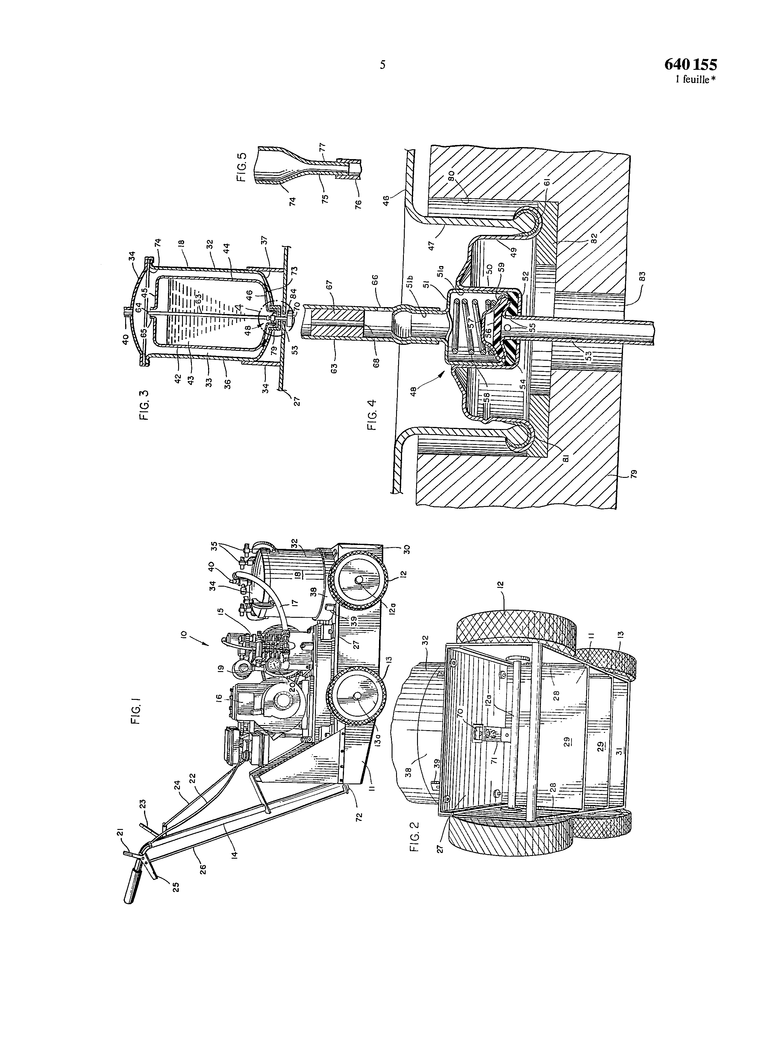
Claims I cartridge containing a material to be sprayed and for mounting in a sputtering apparatus having a casing (32) forming a pressure chamber (33), characterized in that the cartridge comprises a valve (48) having a valve stem (53) extending from the valve (48) to the outside of the chamber for delivering the contents of this cartridge when said valve is open, a tube (63) provided in the cartridge, extending from the valve and terminating in an end that lies above the level of the contents of the cartridge when this is placed such that its valve is located at the base, the tube having an opening (66) between the valve and the tube rextrémité , the latter including a pressure reducing device (67, 75) provided between the opening and the end of this tube (64) to reduce the pressure of the gas flowing there through this, and means on the cartridge for communicating the upper end (65) of this iartouche PREA outside when the cartridge is piace so that its valve is located at the base, so that the pressure on the contents of the cartridge is the same as the pressure in the pressure chamber and so that, when the valve is open, the pressure in the tube, close to its opening, is less than the pressure of the contents of the cartridge and the cartridge contents flows through the opening and mixes with the gas flowing within the tube, the mixture passing through the valve section to outside of the chamber.2. the cartridge according to claim 1, characterized in that the means communicating the upper end of the cartridge (42) with the outside thereof is an opening in the cartridge pratiquéc .3. the cartridge according to claim 1, characterized in that the diameter of the bore of the tube (63) wherein flows the pressurized gas is reduced before the aperture (66) provided in the tube, to form the pressure reduction device (67, 75).4. the cartridge according to claim 1, characterized in that the pressure reduction device is constituted by a cap (67) provided in the tube (63) and having a through hole (68) smaller than the diameter of the bore of the tube.The cartridge of claim 1, characterized in that the tube (63) comprises a venturi section (75) which constitutes the pressure reducing device, the opening (77) being located in said venturi section.6. spraying apparatus comprising a cartridge according to claim 1, characterized in that it comprises a frame (11) provided with wheels (12, 13) and means mounting the frame for supplying pressurized gas to the pressure chamber (33) engine.7. apparatus according to claim 6, characterized in that it comprises a spray nozzle (70) mounted on the valve stem (53), for spraying the contents of the cartridge (42) that flows through the valve when open, and means on the frame (11) for moving the valve rod (53) in order to open it.The present invention relates to a cartridge according to the preamble of claim 1 and to a spraying apparatus according to claim 6.It is common practice to spray materials, suchre uests paints, and so forth, by aerosol propellants. A propellant aerosol is enclosed in a box with the material which is to be sprayed, and flushing the propellant force the material through a spray orifice, when a valve is opened, for atomizing and spraying the material. The use of propellants such however has several disadvantages. Aerosol propellants are relatively expensive and the volume of the box is generally relatively small, typically with dimensions for the hand held. As soon as this box has been video, usually discarded. This not only creates a potential danger due to any amount any propellant remaining in the canister, but also increases the total cost of the sputtering apparatus.Known guns for spraying paints. These spray guns can be controlled by pressurized gas rather than aerosol propellants, and they have a greater capacity for spraying a greater volume of liquid aerosol l0 as a tote. However, these spray guns require ordinarily considerable time cleaning spray when the work is completed is exacerbated when spraying another material, for example a paint of a different color. An advantage of aerosol spray cans with respect to the spray guns is that the cleaning of tanks, of canalisaùtions , nozzles, and so on, is not required.The problem of the present invention is to provide a cartridge that can be used in a sputtering apparatus of large capacity and can be simply replaced. This problem is solved by the features of claim 1.The invention further provides for the spray apparatus according to the features of claim 6.The invention will be described by way of example and with reference to the accompanying drawings.Fig. 1 is a perspective view of a spray apparatus according to the invention.Fig. 2 is a partial perspective view of the lower front portion of the sputtering apparatus.Fig. 3 is a partial sectional view, taken through the pressure chamber and the cartridge of the apparatus of pulvéñsation .Fig. 4 is an enlarged partial view of the lower portion of fig. 3.Fig. 5 is a partial sectional view of a particular embodiment of a pressure reducing device.The Figures 1 and 2 illustrate a sputtering apparatus 10 that is designed to run on a surface that is to be provided with a spray. Such a spraying apparatus for spraying is attractive a marking material, such as a paint or dye, on a surface, a road surfaeeteile , turf, and so on, to mark parking areas, limits, like it must however be understood that the invention can also be utilized in a sputtering apparatus other than of the type fitted with wheels, and that it can also be used for spraying a material other than paint.The sputtering apparatus 10 includes a frame 11 supported by a pair of front wheels 12 and a pair of wheels 13 bitter.A handle 14 is attached to the chassis to permit pushing the apparatus on the surface to be sprayed.An air compressor 15 is driven by an internal combustion engine 16, to supply air under pressure through a conduit 17 to a pressure vessel 18. an accumulator 19 communicates with the outlet of the compressor, and a pressure controller 20 controls the flow of air to the pressure vessel.Various controls for the sputtering apparatus are mounted on the end of the handle, to reach suitable operator. A throttle control lever 21 is momé pivotally on the handle and is connected to the carburetor of the engine by a sheathed cable 22 for adjusting the speed of the motor. A clutch lever 23 is pivotally mounted on the handle and is connected to a conventional clutch (not shown) by a tringlefie 24. The clutch transmits power from the engine to the rear wheels, to cause the movement of the apparatus. A control handle is pivotally mounted on the handle for pulling a rod 26, to cause opening of the valve that the OH pulvéñsation then described.The chassis includes a top wall 27 (Figure 2), a pair of side walls 28 and a pair of transverse walls 29, forming spiders. A front wall, designated by 30 on Figure 1 but omitted for clarity of the Figure. 2, and a rear wall 31 respectively extend between the leading edges and!in ES rear edges of the side walls. Axes 12a and 13a respectively extend for!in ES front wheels and the rear wheels through!in ES sidewalls 28.The pressure vessel! 8 comprises a casing constituted by a main portion 32, which constitutes a chamber internal pressure (Figure 3) 33, 34 and by a cover that is removably attached to the main portion by clamping means 35. The casing includes a cylindrical side wall and a bottom wall 36 37 dome-shaped and is supported by a collar 38 which l0 is attached, as by welding or brazing, to the lower part of the cylindrical side wall. This collar 38 is attached to the top wall 27 of the frame by brackets angular 39. The air channel 17 is connected to an intake device 40 provided on the lid of the pressure vessel to supply pressurized air to the pressure chamber. A bleed valve may be provided on the intake device 40 for allowing the escape of the pressure in the pressure vessel after engine shutdown.A cartridge 42, of general cylindrical configuration and contains the spraying material 43, is introduced into the pressure chamber and includes a cylindrical side wall 44. a top wall 45 and a bottom 46. If program can now to the fig.. 4, the bottom 46 includes a collar 47 extending downward and forming a valve opening, a valve assembly 48 is inserted in the opening and secured to the collar. The valve assembly may be a valve 2s traditional that the OH is a standard in the LOS pulvéñsation aerosol cans. The valve assembly shown in fig. 4 specifically includes a support frame 49 which forms a valve housing 50, cup-shaped, an inlet tube 51, having a large diameter portion 51 has, fixed to its inner surface of the valve housing, said inlet tube also having a reduced diameter portion 51 b inhibitors. An annular packing 52 which acts as a valve seat is placed at the bottom of the valve housing, and a valve stem 53 extends through the insert and into the valve housing. The upper end of the valve stem having a sealing flange 54, extending outwardly and downwardly, which engages the liner 52, one or more openings being provided in the valve stem, just below the sealing flange. A second liner 56 is pressed against the upper end of the valve stem for sealing a metal upper end, this pressure being provided by a sealing coupeUe 57 which is urged downward by a spring 58. The cup seal comprises a shoulder 59 which presses down on the packing 56 and on the sealing flange 54 to provide sealing engagement with the gasket 52.When the valve is in the position shown by the Figure. 4, it is closed. This valve can be opened by pushing the valve stem upward, either by tilting the upper end of the valve stem in a lateral direction. When the stem is flipped, it pivots about a portion of the sealing flange 54 and raises!' a openings 55 above the insert 52. The insert 56 and the cup seal 57 are then tilted upward, and the cartridge contents can flow all around the cup seal 57, through the apertures 55 s5 valve rod. The valve assembly is attached to the collar 47 of the eartouche by crimping the bracket sleeve 49 of the valve assembly around the edge with a bead of said collar. A sealing material 6! is put in between the collar and the crimped edge of!' supporting sheath to maintain a vacuum seal.A tube 63 is connected to the inlet tube 5! of the valve and extends upwardly to a point above the level of the cartridge. In the embodiment shown, the upper end 64 of the tube 63 extends to an opening provided in a collar 65 threaded externally provided on the top wall of the cartridge. The cartridge and the upper end of the tube can therefore êtrc hermetically sealed by screwing a 640,155 cap equipped with a lining to the collar 65. When the cartridge is thus sealed by the cover, it can be carried or stored without wasting its contents, without exposing it to the ALT or without allowing the contents to flow by the end 64 of the tube, even if the cartridge is inverted or lying. A port 66 is provided in the tube, just year above the valve assembly, and the bore of the tube is reduced just above the opening by a cap 67 which has the port 68 of a smaller diameter than the bore of the tube.In view of the Figure. 2, la valve stem 53 extends through an opening in the top wall 27 of the frame 1!, and a spray nozzle 70 is placed on the end of the valve stem. The particular spray nozzle that is depicted is similar to the spray nozzle as described in United States of America no. 3817429, and it comprises a long pulvéñsation port and a pair of planar aligned surfaces. A control bar 7! is mounted slidably on the top wall 27 of the frame, in the vicinity of the spray nozzle, in a manner similar to that described in the patents of the United States of America no. 3700144 and 3817429, and this control bar is connected by a rod to a bellcrank lever 72 (Figure 1) pivotally mounted to the rear of the chassis. When the handle 25 is pulled upward, the rod 26 rotates the bell crank, and the drive rod moves forward to cooperate with the spray nozzle.A movement of the spray nozzle forward tilts the valve stem and opens it.When the sputtering apparatus is to be used, the cover 34 of the pressure vessel 18 is removed and placing a cartridge 42 contains the spraying material, for example a paint of a particular color, within the main portion of the pressure vessel. The cartridge 42 is supported in this pressure vessel by an annular sealing gasket 73 (Figure 3) which is attached on the bottom of the pressure vessel, and a lining 74 provides a tight seal between the cover 34 and the main portion 32 of the pressure vessel, when the cover is clamped in place. The existing opening thereof with the pressure chamber 33 and, when the pressure vessel is pressurized by the air compressor, the pressures prevailing in the chamber 33, the tube 63 and the cartridge 44 are the same.The valve stem 53 is at atmospheric pressure when the valve 48 is closed. When the window is opened, air under pressure flows through the tube 63 and through the valve.The performance bottleneck 67 limits the flow of pressurized air through the tube from the upper end, and the air pressure existing in the tube, below the throttle device, is lower than the air pressure in the pressure vessel.As the pressure of the contents of the cartridge around the orifice 66 of the tube is in fact the pressure of the pressure vessel, the contents of the cartridge will flow through this orifice, will be driven by the air flowing through the tube and will flow through the valve into the spray nozzle. It atomizing and spraying the contents in downwards direction, towards the surface on which the spraying apparatus is busy to move.In the embodiment shown in fig.. 4, the performance bottleneck 67 acts as means for reducing the pressure of the gas flowing through the tube when the valve is open. However, one can employ other pressure reducing means. Fig. 5 illustrates a tube 74 having a venturi section 75 for reducing the pressure of the gas flowing through the tube to the inlet tube of the valve 76. The port 77 is provided in the venturi section, and the contents of the cartridge is drawn through this orifice in the tube 76.In the embodiment shown in fig.. 4, the port 66 is provided in the tube 63 between the plug throttle 67 and the inlet tube of the valve 51. However, the induction tube 51 is an extension of the tube may also be provided in the induction tube 51, or elsewhere between the plug member and the throttle valve closure.640,155 a plug adapter 79 (Figures 3 and 4), externally threaded, is screwed into an opening in the bottom 37 of the pressure vessel, and the collar 47 of the cartridge, downwardly extending, to which the valve assembly is attached, is placed within a cylindrical cavity of the adapter. The crimped edge 81 of the support sleeve of the valve assembly cooperates with a ring gasket 82 supported in the IC adapter cap 79, and the valve shaft 53 sëtend 83 through an opening provided in the bottom of the plug adapter 79 and through an opening 84 (Figure 3) existing in the top wall 27 of the chassis. The cartridge 42 is pushed down against the liners 82 and 73 by the weight of the cartridge and by the pressure in the pressure vessel 18, and the lid of a pressure vessel which is sealed inside the adapter 74, to thereby ensure the tight closure of the récipieut to pressure.When the contents of the cartridge 42 has been emptied or when it is desired to change the material to be pulverized, for example when it is necessary to spray a paint of a different color, the only necessary procedure involves opening the lid 34 of the pressure vessel 18, removing the spray nozzle 70 from the end of the valve stem 53 and lift the cartridge 42 out of the pressure vessel. The new cartridge is then inserted into it so the bottom 46 and the crimped edge 81 come into sealing contact with the linings 73 and 82, and then the cover is closed and a new spray nozzle 70 is brought into piace on the valve shaft 53. The cartridge replacement takes only a few seconds.The contents of the cartridge 42 is never in contact with pressure vessel 18, but is held entirely within the cartridge, and it is not necessary to clean the pressure vessel, either when the cartridge is replaced, or when the spraying operation is completed. Further, the sputtering apparatus does not use pipes, nozzles complicated, and so on, which generally require a cleaning. The spray nozzle may be a nozzle inexpensive, molded plastic, which can be disposed of after each use.As the cartridge does not require pressure resistance, the pressures both within and outside of the cartridge being equai to the pressure acting in the pressure vessel, the cartridge may be made of an inexpensive material, for example of molded plastic material. Accordingly, economically, the cartridge may be discarded when empty. Alternatively, the cartridge can be recharged by introducing extra material by the ouyerture formed by the threaded collar 65. A cartridge rez0 vacuum may be partially occluded, and stored for later use, by screwing a cap internally threaded on the end of the collar 65 to seal the opening of the collar and sealing the upper end 64 of the tube 63.Le if desired, the apparatus may be provided with pnlvérisation ls means for modifying the width of the strips of OH sprayed by the nozzle 70. By way of example, the height of the nozzle, c'està meaning the distance between the nozzle and the surface to be sprayed, may be adjustable, or the orientation of the elongate spray port, relative to the direction in which the apparatus is moved, is adjustable, and as described in the Patent of the United States of America no. 3924784.A spray apparatus made according to the present invention is capable of operating efficiently at a relatively low pressure. By way of example, when the apparatus is used for spraying paint 2s having a viscosity falling in the normal intervaIle viscosities accepted in the industry, the apparatus can operate at a pressure less than 0.68 n/mm2. By expression interval viscosities accepted in industry, designating a viscosity in the range of 17 to 32 seconds, teile that measured by Zahn heading to a temperature of about 26 °c. The relative dimensions of the inner diameter of the air tube 63 and the diameter of the intake port 66 paint can be such that the ratio of these diameters is in the range of 1/1 to 40/1.Although provision being made that the source of pressurized gas or a 3s air compressor, motor-driven, it is understood that the OH may use other feeding means, for example bottles of compressed air, other gas even-Tu.The R 1 sheet drawings 640,155 1 * sheet A spraying apparatus utilizes pressurized gas to spray liquid contained in a large replaceable or refillable cartridge. The cartridge is positioned within a casing which provides a pressure chamber, and a source of pressurized gas is attached to the casing to pressurize the chamber. The top of the cartridge communicates with the chamber so that the liquid is also pressurized. A tube extends from above the level of the liquid in the cartridge to the bottom of the cartridge and is attached to a valve. An opening is provided in the tube adjacent to the bottom of the cartridge, and the diameter of the tube is reduced above the opening to restrict the flow of gas through the tube and to create a pressure differential in the tube. When the valve is open, pressurized gas flows through the tube, and, since the pressure of the gas inside the tube at the opening is less than the pressure of the liquid, liquid flows through the opening, mixes with the gas within the tube, and flows through the valve. 1. A spraying apparatus comprising a casing providing an internal chamber adapted to be supplied with pressurized gas, a cartridge within the casing, the cartridge containing contents to be sprayed and having an upper end and a lower end, the upper end of the cartridge above the contents thereof communicating with the chamber so that the pressure of the contents of the cartridge and the pressure within the chamber are substantially equal, a tube within the cartridge extending into the contents of the cartridge and having an end communicating with the chamber, a valve attached to the tube and communicating with the outside of the chamber, the tube being provided with an opening below the level of the contents of the cartridge and between the valve and said end of the tube, and pressure-reducing means between the opening and said end of the tube for reducing the pressure of gas flowing through the tube whereby when the valve is open the pressure within the tube adjacent to the opening is less than the pressure of the contents of the cartridge and the contents flow through the opening and mix with gas flowing through the tube and the mixed contents and gas flow through the valve to the outside of the chamber. 2. The apparatus of claim 1 including a valve stem extending from the valve to the outside of the chamber and a spraying nozzle mounted on the valve stem for spraying the contents of the cartridge which flow through the valve when the valve is open. 3. The apparatus of claim 1 in which the diameter of the bore of the tube through which the pressurized gas flows is reduced upstream of the opening into the tube to provide the pressure-reducing means. 4. The apparatus of claim 1 in which the pressure-reducing means is a plug within the tube having a bore smaller than the bore of the tube. 5. The apparatus of claim 1 in which the tube includes a Venturi section which provides the pressure-reducing means, the opening being located in the Venturi section. 6. The apparatus of claim 1 in which the cartridge is removably mounted within the casing whereby the cartridge can be replaced when the contents thereof have been emptied. 7. The apparatus of claim 1 in which the valve is attached to the lower end of the cartridge and the casing is provided with an opening adjacent to the valve, and a gasket surrounding the valve and the opening in the casing between the lower end of the cartridge and the casing for preventing pressurized gas from passing through the opening in the casing. 8. The apparatus of claim 1 in which the spraying apparatus includes a wheel-equipped frame and means mounted on the frame for supplying pressurized gas to the chamber of the casing. 9. The apparatus of claim 8 including a valve stem extending from the valve to the outside of the chamber, a spraying nozzle mounted on the valve stem for spraying the contents of the cartridge which flow through the valve when the valve is open, and means on the frame for moving the valve stem for opening the valve. 10. A cartridge for use with a spraying apparatus having a casing providing a pressure chamber, the cartridge containing contents to be sprayed, a valve mounted on the cartridge for conveying the contents out of the cartridge when the valve is open, a tube in the cartridge extending from the valve and terminating in an end which is positioned above the level of the contents when the cartridge is positioned so that the valve is at the bottom thereof, the tube being provided with an opening between the valve and said end of the tube and pressure-reducing means in the tube between the opening and said end of the tube for reducing the pressure of gas flowing through the tube, and means on the cartridge for communicating the upper end of the cartridge with the outside of the cartridge when the cartridge is positioned so that the valve is at the bottom of the cartridge whereby the pressure on the contents is the same as the pressure in the pressure chamber. 11. The cartridge of claim 10 in which the means for communicating the upper end of the cartridge with the outside of the cartridge is an opening in the cartridge. 12. The cartridge of claim 10 in which the diameter of the bore of the tube through which the pressurized gas flows is reduced upstream of the opening into the tube to provide the pressure-reducing means. 13. The cartridge of claim 10 in which the pressure-reducing means is a plug within the tube having a bore smaller than the bore of the tube. 14. The cartridge of claim 10 in which the tube includes a Venturi section which provides the pressure-reducing means, the opening being located in the Venturi section.