ELECTRIC PUMP SYSTEM AND METHOD
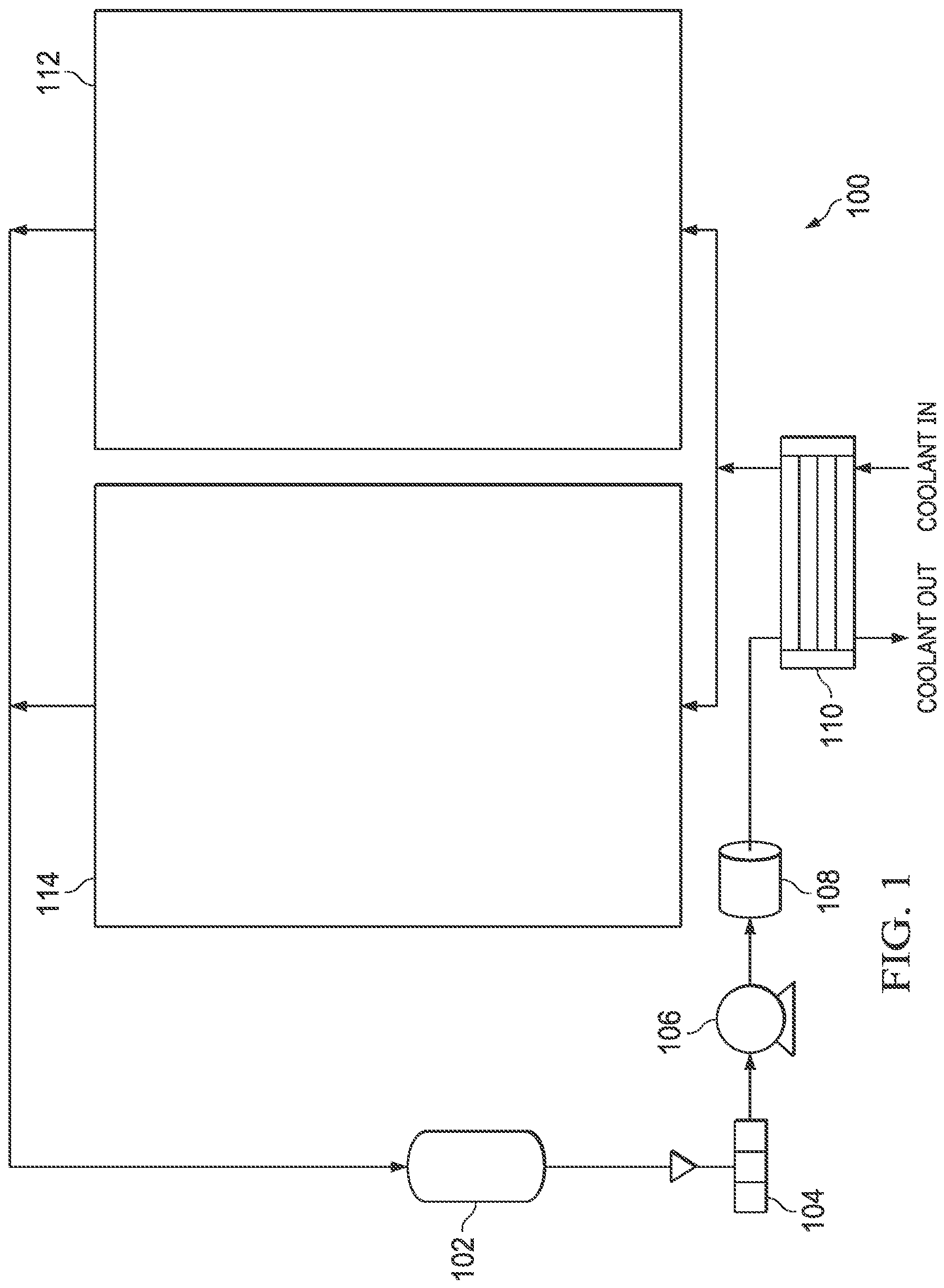
The present PCT application claims priority to The present PCT application is related to The present invention relates to electric pump systems, and more particularly to the transfer of heat, and assessment of fluid temperature in electric pump systems, such as those used in the drive system of a vehicle. An electric pump system in the drive system of an electric vehicle, for example, may be used to provide oil to the bearings, rotor and stator of a traction motor, amongst other places, in order to cool and lubricate the traction motor. Such electric pump systems typically include a mechanical pump, an electric motor as well as electronics for controlling the electric pump system. Challenges associated with designing such electric pump systems include designing a pump system with desired flow properties. Traditional oil pumps do not monitor oil condition and thus require oil to be changed on a regular basis because the condition of the oil, pump, and motor cannot be independently verified. A further byproduct is that traditional oil pump is not designed to (and cannot) accurately determine temperature, in part, because any temperature sensor is located either outside of the traditional pump system or in a region representative of the oil flowing through the pump. Further, traditional oil pumps are often large and unwieldy due to attachment mechanisms of different parts and requires a larger physical space for the pump. There is a need, therefore, for an improved oil pump, particular an electric pump system, designed to work in conjunction with an electric motor. The present disclosure presents methods and structures that help overcome the difficulties of operating a cooling and lubrication system, in particular, managing the transfer of heat and assessment of fluid temperature in electric pump systems. According to one aspect of the present disclosure, there is provided an apparatus that includes an electronic control unit, a mechanical pump, and a motor having a first side and a second side, the motor including: a stator, a rotor including a hollow shaft, and a housing around the stator and rotor, wherein the electronic control unit is connected to the first side of the motor, wherein the mechanical pump is connected to the second side of the motor, wherein the hollow shaft defines a shaft inlet and a shaft outlet, wherein the mechanical pump defines a first fluid passageway from a first pump inlet to the shaft inlet, wherein the housing defines an internal motor cavity, wherein the shaft outlet is in fluid communication with the internal motor cavity, wherein the mechanical pump defines a second fluid passageway from a second pump inlet to a pump outlet, and wherein the motor housing and mechanical pump define a third fluid passageway from the internal motor cavity to the pump outlet via a third pump inlet. In some embodiments the apparatus according to the above-described aspect of the present disclosure or any other aspects thereof, a number of optional operations and features may be employed. One optional feature is the electronic control unit further including a thermistor to measure a temperature of a fluid exiting the shaft outlet. Another optional feature is wherein the housing defines a bypass inlet in fluid communication with the internal motor cavity. Another optional feature is at least a portion of the second fluid passageway and the third fluid passageway is common. Another optional feature is the mechanical pump is a gerotor. Another optional feature is the electronic control unit includes a microcontroller controlling the mechanical pump. Another optional feature is the electronic control unit includes cooling ribs. According to one aspect of the present disclosure, there is provided a method of pumping a fluid in an electric pump system including pumping the fluid through a first fluid passageway from a first pump inlet to a shaft inlet, through a hollow shaft of a motor from the shaft inlet to a shaft outlet, and into an internal motor cavity of the electric pump system that is in fluid communication with the shaft outlet, through a second fluid passageway from a second pump inlet of a mechanical pump to a pump outlet of the mechanical pump, and through a third fluid passageway defined in a motor housing of the electric pump system and in the mechanical pump from the internal motor cavity to the pump outlet via a third pump inlet. In some embodiments the method according to the above-described aspect of the present disclosure or any other aspects thereof, a number of optional operations and features may be employed. One optional feature is measuring a temperature of the fluid exiting the hollow shaft. Another optional feature is providing the fluid to the internal motor cavity through a bypass inlet defined in the motor housing of the motor. Another optional feature is including pumping the fluid from a bypass inlet to the internal motor cavity. Another optional feature is the mechanical pump includes a gerotor. Another optional feature is controlling the mechanical pump with an electronic control unit including a microcontroller. According to one aspect of the present disclosure, there is provided a system including an apparatus including a mechanical pump, an electronic control unit, and a motor having a first side and a second side, the motor including a stator, a rotor including a hollow shaft and a housing around the stator and rotor, wherein the electronic control unit is connected to the first side of the motor, wherein the mechanical pump is connected to the second side of the motor, wherein the hollow shaft defines a shaft inlet and a shaft outlet, wherein the mechanical pump defines a first fluid passageway from a first pump inlet to the shaft inlet, wherein the housing defines an internal motor cavity, wherein the shaft outlet is in fluid communication with the internal motor cavity, wherein the mechanical pump defines a second fluid passageway from a second pump inlet to a pump outlet, and wherein the motor housing and mechanical pump define a third fluid passageway from the internal motor cavity to the pump outlet, via a third pump inlet, a heat exchanger in fluid communication with the pump outlet, and an oil reservoir in fluid communication with the first pump inlet and the second pump inlet. In some embodiments the method according to the above-described aspect of the present disclosure or any other aspects thereof, a number of optional operations and features may be employed. One optional feature is the electronic control unit further includes a thermistor to measure a temperature of a fluid exiting the shaft outlet. Another optional feature is the housing defines a bypass inlet in fluid communication with the internal motor cavity. Another optional feature is at least a portion of the second fluid passageway and the third fluid passageway is common. Another optional feature is the mechanical pump is a gerotor. Another optional feature is the electronic control unit includes a microcontroller controlling the mechanical pump. Another optional feature is the electronic control unit includes cooling ribs. Starting from oil reservoir 102, which may include a sump or dry-sump system (oil reservoir external to the drive unit), oil flows through meshed filter 104 to electric pump system 106. Oil pumped out of electric pump system 106 passes through oil filter 108 and heat exchanger 110 and splits between a first branch that leads to motor 112 and another that leads to gear box 114. Oil from both branches drains back to oil reservoir 102. Various operational issues with the cooling and lubrication system 100 are described herein in conjunction with various embodiments. One operational issue relates to heat exchange within the electric pump system 106. Another operational issue relates to assessing and controlling the temperature of oil in the cooling and lubrication system 100. The oil temperature may be controlled by heat transfer in heat exchanger 110, i.e., exchange of heat between the vehicle coolant and the oil. Firmware or software typically controls the Engine Control Unit (ECU) which is not shown in Also shown in Also shown in Also shown in Also show in Fluid passageway 1115 may also be referred to as the first fluid passageway. Main pump inlet 1120 may also be referred to as the first pump inlet. Fluid passageway 1126 may also be referred to as the second fluid passageway. Pump inlet 1124 may also be referred to as the second pump inlet. Fluid passageway 1114 may also be referred to as the third fluid passageway. Secondary pump inlet 1116 may also be referred to as the third pump inlet. A benefit of the system and method of the disclosed embodiments, is that very little heat is absorbed by the fluid from operation of electric pump system 106 when the fluid is exiting hollow shaft 706. By measuring at this point, ECU 206 can, therefore, get an accurate reading of the fluid prior to being substantially heated by electric pump system 106, but without having to use sensors positioned at or near the pump inlets which would necessitate communications channels for relaying information to ECU 206 thereby adding expense, complexity and additional points of failure. Information regarding the temperature of the fluid prior to being substantially heated by electric pump system 106 can be used for purposes of determining how much heat needs to be rejected from the fluid and what changes to make to the operation of the associated vehicle (e.g. reduce torque). As will be appreciated by one of skill in the art, a slow rotating gear requires oil of a specific viscosity to stick to its surface. A gear of the same size with much higher rotational speed, e.g. at a reduction gear stage before the one above, may require a different temperature of oil in order to have it stick to the gear surface because the centrifugal forces are much higher. If the temperature is the same, because two separate oil temperatures are not available in the gearbox, one could use much more oil more orifices for the fast rotating gear. According to embodiments described herein, the fluid temperature can be used to control and attempt to optimize the cooling and lubrication system of a vehicle so as to improve the efficiency of the associated electric drive unit. Specifically, the fluid temperature may be controlled to achieve certain lubrication properties. For example, hotter oil has lower viscosity which reduces drag and hydraulic power to pump the fluid, which can increase efficiency. If the oil becomes too hot, however, it will not provide sufficient cooling. The fluid temperature reading feature of the oil pump can monitor the general health and performance of the fluid in the electric drive unit system. For example, if the oil is too hot, the oil pump may alert the car computer that something is wrong, for oil that is too hot can damage or/and reduce the life of some components on the drive unit. Stated another way the temperature of fluid may be used to monitor the health and performance of the drive unit. The ECU may capture other information besides the temperature, such as pump speed, pump current composition, oil pressure, or other information. The information captured by the ECU may then be fed into a proprietary algorithm that monitors oil pump and overall drive unit health. The algorithm may provide an indication of service, such as when oil must be replaced or when the drive train needs to be serviced. In the foregoing specification, the disclosure has been described with reference to specific embodiments. However, as one skilled in the art will appreciate, various embodiments disclosed herein can be modified or otherwise implemented in various other ways without departing from the spirit and scope of the disclosure. Accordingly, this description is to be considered as illustrative and is for the purpose of teaching those skilled in the art the manner of making and using various embodiments of the disclosed system, method, and computer program product. It is to be understood that the forms of disclosure herein shown and described are to be taken as representative embodiments. Equivalent elements, materials, processes or steps may be substituted for those representatively illustrated and described herein. Moreover, certain features of the disclosure may be utilized independently of the use of other features, all as would be apparent to one skilled in the art after having the benefit of this description of the disclosure. As used herein, the terms "comprises," "comprising," "includes," "including," "has," "having" or any contextual variants thereof, are intended to cover a non-exclusive inclusion. For example, a process, product, article, or apparatus that comprises a list of elements is not necessarily limited to only those elements, but may include other elements not expressly listed or inherent to such process, product, article, or apparatus. Further, unless expressly stated to the contrary, "or" refers to an inclusive or and not to an exclusive or. For example, a condition "A or B" is satisfied by any one of the following: A is true (or present) and B is false (or not present), A is false (or not present) and B is true (or present), and both A and B is true (or present). Although the steps, operations, or computations may be presented in a specific order, this order may be changed in different embodiments. In some embodiments, to the extent multiple steps are shown as sequential in this specification, some combination of such steps in alternative embodiments may be performed at the same time. The sequence of operations described herein can be interrupted, suspended, reversed, or otherwise controlled by another process. It will also be appreciated that one or more of the elements depicted in the drawings/figures can also be implemented in a more separated or integrated manner, or even removed or rendered as inoperable in certain cases, as is useful in accordance with a particular application. According to one aspect of the present disclosure, there is provided an apparatus comprising a motor having a first side and a second side, the motor including a stator, a rotor comprising a shaft, and a housing around the stator and rotor and defining an internal motor cavity and a bypass inlet in fluid communication with the internal motor cavity; an electronic control unit connected to the first side of the motor; a mechanical pump connected to the second side of the motor and defining a first fluid passageway from a first pump inlet to a pump outlet; and wherein the motor housing and mechanical pump further defining a second fluid passageway from the internal motor cavity to the pump outlet via a second pump inlet. The electronic control unit may further comprise a thermistor. The shaft may be a hollow shaft that defines a shaft inlet and a shaft outlet, wherein the mechanical pump may define a third fluid passageway from a third pump inlet to the shaft inlet, and wherein the shaft outlet may be in fluid communication with the internal motor cavity. At least a portion of the first fluid passageway and the second fluid passageway may be common. The mechanical pump may be a gerotor. The electronic control unit may include a microcontroller controlling the mechanical pump. The electronic control unit may include cooling ribs. According to another aspect of the present disclosure, there is provided a method of pumping a fluid in an electric pump system having a mechanical pump and a motor housing defining an internal motor cavity, the method comprising: pumping the fluid through a first fluid passageway from a first pump inlet of the mechanical pump to a pump outlet of the mechanical pump; pumping the fluid through a bypass inlet defined in the motor housing and in fluid communication with the internal motor cavity; and pumping the fluid through a second fluid passageway defined in the motor housing and in the mechanical pump from the internal motor cavity to the pump outlet via a second pump inlet of the mechanical pump. The method may further comprise measuring a temperature of the fluid using a thermistor. The method may further comprise pumping the fluid through a third fluid passageway from a third pump inlet of the mechanical pump to a hollow shaft that defines a shaft inlet and a shaft outlet, wherein the shaft outlet may be in fluid communication with the internal motor cavity. The method may further comprise pumping the fluid through a gap formed between the motor housing and an electronic control unit into the internal motor cavity. The mechanical pump may include a gerotor. The method may further comprise controlling the mechanical pump with an electronic control unit including a microcontroller. According to another aspect of the present disclosure, there is provided a system comprising an apparatus including: a motor having a first side and a second side, the motor including a stator, a rotor comprising a shaft, and a housing around the stator and rotor and defining an internal motor cavity and a bypass inlet in fluid communication with the internal motor cavity; and an electronic control unit connected to the first side of the motor; a mechanical pump connected to the second side of the motor and defining a first fluid passageway from a first pump inlet to a pump outlet, wherein the motor housing and mechanical pump further define a second fluid passageway from the internal motor cavity to the pump outlet via a second pump inlet; a heat exchanger in fluid communication with the pump outlet; and an oil reservoir in fluid communication with the first pump inlet. The electronic control unit may further comprise a thermistor. The shaft may be a hollow shaft that defines a shaft inlet and a shaft outlet, wherein the mechanical pump may define a third fluid passageway from a third pump inlet to the shaft inlet, and wherein the shaft outlet may be in fluid communication with the internal motor cavity. At least a portion of the first fluid passageway and the second fluid passageway may be common. The mechanical pump may be a gerotor. The electronic control unit may include a microcontroller controlling the mechanical pump. The electronic control unit may include cooling ribs. An electric pump system and method of operating the same involves pumping a fluid through a fluid passageway defined in a mechanical pump from a pump inlet to a hollow shaft of a motor, through the hollow shaft to an internal motor cavity defined by a housing of the motor, and through another fluid passageway defined in the motor housing and mechanical pump that leads to a pump outlet. The system and method further involve pumping the fluid through another fluid passageway defined in the mechanical pump from yet another pump inlet to the pump outlet. The temperature of fluid exiting the hollow shaft can be assessed and used by an electronic control unit (ECU) of the electric pump system to control the same. The electric pump system can be part of a cooling and lubrication system for an electric vehicle transmission, gearbox, differential or transfer case, for example.
A vehicle comprising a drive system and an electric pump system (106) in the drive system, the electric pump system (106) comprising:
a motor (112, 204) including:
a stator (1106); a rotor (704) comprising a hollow shaft (706); and a housing (210, 402, 404) around the stator (1106) and rotor (704) and defining an internal motor cavity (1108); an electronic control unit (206) connected to the motor (112, 204), the electronic control unit comprising a thermistor (1016) configured to measure a temperature of a fluid; a mechanical pump (202) comprising a first pump inlet (1120), a second pump inlet (1124), and a pump outlet (208), the mechanical pump connected to the motor (112, 204) through the second pump inlet (1124); a first fluid passageway (1115) from the first pump inlet to the pump outlet (208); and a second fluid passageway (1126) extending through the internal motor cavity (1108) to the pump outlet via the second pump inlet, wherein information regarding the temperature of the fluid is used to determine a change to make to an operation of the vehicle. The vehicle of claim 1, wherein at least a portion of the first fluid passageway (1115) and the second fluid passageway (1126) is common. The vehicle of claim 1, wherein the mechanical pump is a gerotor. The vehicle of claim 1, wherein the electronic control unit (206) includes a microcontroller (1012) controlling the mechanical pump (202). The vehicle of claim 1 further including a bypass inlet (216) in fluid communication with the internal motor cavity (1108). The vehicle of claim 1, wherein the change to the operation of the vehicle comprises a reduction of torque. The vehicle of claim 1, wherein the electronic control unit (206) includes cooling ribs (214). The vehicle of claim 1, wherein the thermistor (1016) is configured to measure a temperature of a fluid exiting a shaft outlet of the hollow shaft. The vehicle of claim 1, wherein the motor comprises a first side and a second side;
wherein the electronic control unit (206) is connected to the first side of the motor; and the mechanical pump is connected to the second side of the motor (112, 204) through the second pump inlet. The vehicle of claim 1, wherein the electronic control unit comprises a PCB (1002) and a second thermistor (1010), wherein the second thermistor is configured to measure the temperature of the PCB. The vehicle of claim 1, wherein the electronic control unit comprises a PCB (1002) and a plurality of mounting legs (1006) that support the PCB. A method of pumping a fluid in an electric pump system (106) having a mechanical pump (202), a motor including a stator (1106) and a rotor (704) comprising a hollow shaft (706), and a motor housing (210, 402, 404) defining an internal motor cavity (1108), the method comprising: pumping the fluid along a first fluid flow path through a first fluid passageway (1115) from a first pump inlet (1120) of the mechanical pump to a pump outlet (208) of the mechanical pump; pumping the fluid along a second fluid flow path through a second fluid passageway (1126) from the internal motor cavity to the pump outlet via a second pump inlet (1124) of the mechanical pump, wherein the fluid along the second fluid flow path flows through the hollow shaft of the rotor from a shaft inlet (1110) to a shaft outlet (1112) into the internal motor cavity, past the stator and the rotor and through the motor housing into the second fluid passageway (1126); measuring, via a temperature sensor (1016) located adjacent to the shaft outlet, a temperature of the fluid exiting the hollow shaft; and determining, using information regarding the temperature of the fluid exciting the hollow shaft, how much heat needs to be rejected from the fluid and/or a change to make to the operation of a vehicle associated with the electric pump system. The method of claim 12, wherein the measured temperature of the fluid corresponds to a temperature of the fluid prior to the fluid being substantially heated by the electric pump system. The method of claim 12, wherein the change to make to the operation of the vehicle comprises a reduction of torque. The method of claim 12, wherein the mechanical pump is controlled via a microcontroller included in an electronic control unit.CROSS-REFERENCES TO RELATED APPLICATIONS
BACKGROUND
Technical Field
Description of Related Art
SUMMARY
BRIEF DESCRIPTION OF THE SEVERAL VIEWS OF THE DRAWINGS
DETAILED DESCRIPTION OF THE DISCLOSURE