Led 검사 장치 및 led 검사용 디스크
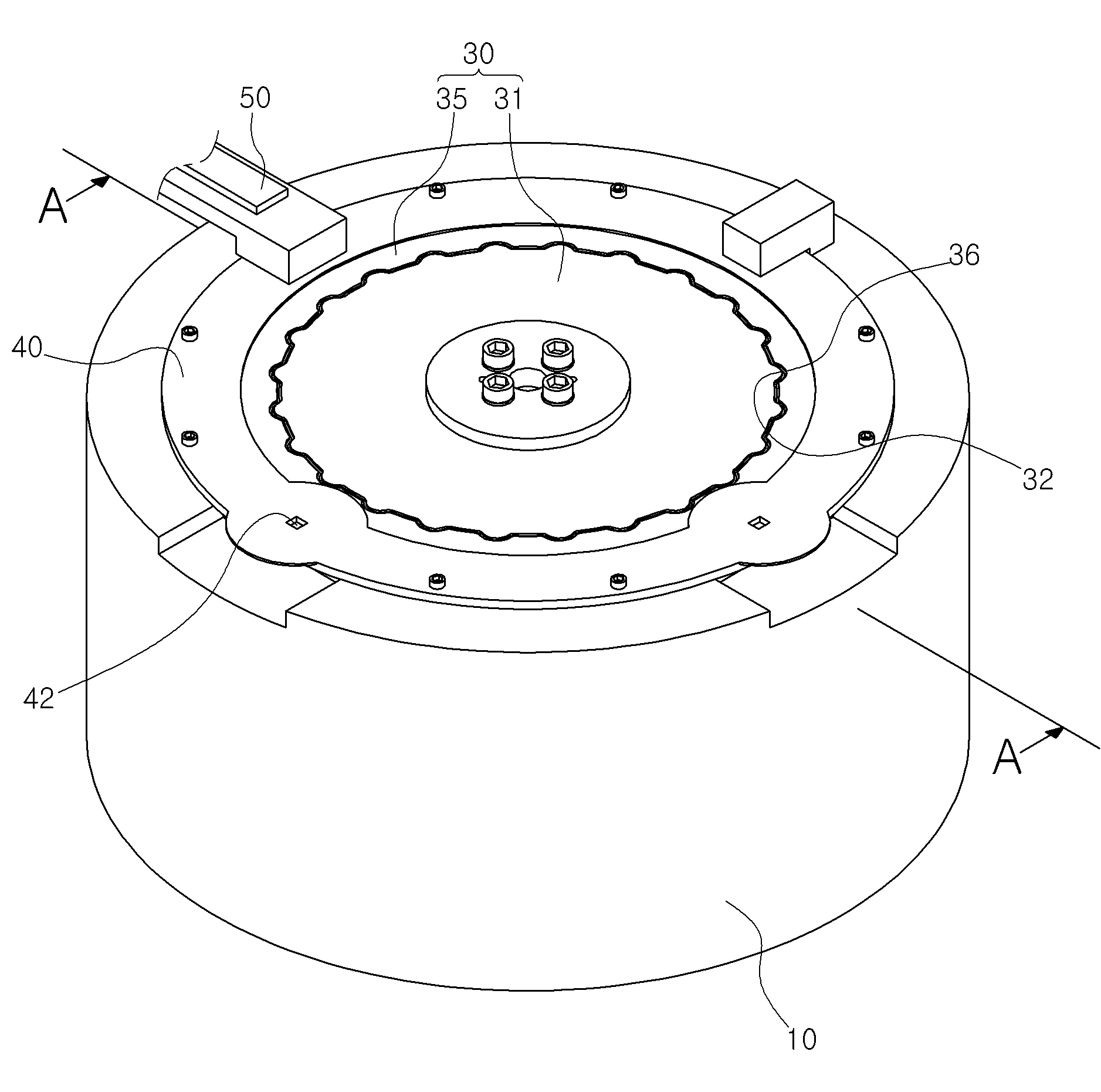
The present invention refers to LED and LED inspection device for testing disk relates to search, in particular LED LED LED inspection device can be equipped with a disk rotated together for testing the disk and LED inspection are disclosed. In LED LED packaging (taping) is first placed in a stand-alone power-off number and failure LED, LED through a predetermined method successfully checked whether taping only needs disclosed. The number it became work order to a LED, various conventional LED inspection device developed in the nanometer range. Of the existing method LED inspection device generally includes, a base member, and comprising a base member rotatably mounted at the top of the disk, the disk is LED and the tray, the tray of a disk rotating LED advertisement to check in the nanometer range. However of the existing method LED inspection device is mounted to the metal disk is made, it is arranged in a lower base member generates friction during rotation, thereby chip, scratch film is to be coated. The disk or base member chip, scratch and the like product is, disk or base member is provided to the door number serious cooling has been. In addition, since the nozzle holes of the entire disk damage, according to the whole structure is equal to the cost. The present invention refers to point in order to solve the aforementioned door number provided, rotating disk disposed on a top base member is fixed between the upper surface of the chip, scratch film is minimizing and protruded toward the disk or base member, damage of the entire some but not replacing only the LED inspection device and can be LED to reduce cost for testing disk number to the pin is. In order to achieve said purposes of the present invention LED inspection device includes, a base member; said base and rotatably mounted at the top, LED is loaded on the disk and the flange; said upper edge separated from the base member is coupled between this standing groove is formed, said disk is rotatably inserted into said in this standing groove disposed, upwardly exposed heating cover member; said base member to said driving member and a lower disk; disposed on a top of said cover member, said flange prevents said LED is placed a disk exposed inspecting DLM; the comprising, said disk, said drive member coupled to the center portion; said insertion disposed in this standing groove consists of a hollow disk shape, an outer circumferential surface of said center section steel plate detachably coupled, said LED is loaded on the flange by reducing the growth; composed, said center circular central outer direction from the outer peripheral surface as an outer clamp and a plurality of protruded spaced equal interval, said central circular periphery has a flange clamp pressed by said inner peripheral surface of the same interval with the recessed inward spaced posts attached to the other surface, each said arc made of detachably coupled body includes, said sunken concave toward the center and then the upper center number 1 only the chin groove formed along the circumference, only the chin groove formed in the outer direction from the inner peripheral surface of said upper flange portion of the sunken number 2 which are situated along the perimeter, said center flange and said case, said outer circumferential surface of the inner peripheral surface of the flange portion of the connection center portion said circumferential surface, said circumferential surface being moved up and down combined arcuate, said center to the outer periphery of the flange portion of the upper inner periphery of the upper surface said number 1 number 2 only in the chin groove spaced from each other by said , said center of said inner peripheral surface of the flange portion contact each other in an lower peripheral surface lower combined, said said upper surface of said base member arranged in a lower section when the disk rotates more than said center flange in contact with the lower surface of the glass fiber is made between said upper surface of said center part arranged in a lower base member and minimize the formation of a discharge port, said LED is loaded on the metal has a flange to prevent interference with other configuration is made on the level can be characterized. Back number Back number Back number In order to achieve said purposes for testing the disk of the present invention LED, LED is mounted on the testing device, for testing LED so that the LED is loaded on the disk, a disk shape of a center portion; a multiplicity of hollow disk shape, an outer circumferential surface of said center section steel plate detachably coupled, said LED by reducing the growth is loaded on the flange portion; wherein, said center circular central outer direction from the outer peripheral surface as an outer clamp and a plurality of protruded spaced equal interval, said central circular periphery has a flange clamp pressed by said inner peripheral surface of the same interval with the recessed inward spaced posts attached to the other surface, each said body includes arc made of detachably coupled, said sunken concave toward the center and then the upper center number 1 only the chin groove formed along the circumference, only the chin groove formed in the outer direction from the inner peripheral surface of said upper flange portion of the sunken number 2 which are situated along the perimeter, said center flange and said case, said outer circumferential surface of the inner peripheral surface of the flange portion of the connection center portion said circumferential surface, said circumferential surface of an arc shape protrusion combined, said center to the outer periphery of the flange portion of the upper inner periphery of the upper surface said number 1 number 2 only in the chin groove spaced from each other by said , said center of said inner peripheral surface of the flange portion contact each other in an lower peripheral surface lower combined, said upper surface of said base member arranged in a lower section when the disk rotates more than said center flange in contact with the glass fiber is made with the lower surface of said center part arranged in a lower friction between the upper surface of the base member to minimize the occurrence of, said LED is loaded on the metal has a flange to prevent interference with other configuration is made on the level can be characterized. Back number Back number Back number LED inspection device such as disk than the following effect according of the present invention LED inspection and flow tides. Rotating disk disposed on a top base member is fixed between the upper surface of the chip, disk or base member to minimize scratch film is to minimize breakage, damage of the entire some but not replacing only can be to reduce cost. Figure 1 shows a schematic diagram of the device according to an embodiment of the present invention LED inspection is also sensors mounted thereon, Figure 2 shows a A provided A cross-sectional drawing of Figure 1, taken the line Figure 3 shows a disk according to an embodiment of the present invention LED also for testing sensors mounted thereon, Figure 4 shows a decomposition of disk for testing also according to an embodiment of the present invention LED sensors mounted thereon. Figure 5 shows a B provided B line takes the cross-sectional drawing of Figure 3. The device of the present invention LED inspection, base member (10) on, drive member (20) on, disk (30) on, cover member (40) on, DLM (50) including combustion chamber. Said base member (10) upper surface of the disk (30) contacting and seated over a coarse flat shape. Said drive member (20) and consists of the invention relates to a, said base member (10) and a lower member, said disk (30) could be bonded each other rotating. Said disk (30) has nearly a disk shape and is, said base member (10) are rotatably mounted on top of. I.e., said disk (30) has said base member (10) coupled to the lower portion of said drive member (20) coupled to, said base member (10) is caused to rotate at the top of the other. Said disk (30) has a center part (31) and a flange part (35) consisting of an. Said center section (31) has a plate-shaped are formed in said drive member (20) coupled to. Said flange (35) are formed in the hollow, said center part (31) detachably coupled to around. I.e., said center part (31) said outer circumferential surface of the flange (35) is provided an interior body is firmly attached to the inner peripheral surface of the housing in order detachably coupled to each other. The, said center part (31) and a flange part (35) may also be used but in different shape, preferably said center portion (31) has nearly a disk shape and is, said flange portion (35) a substantially hollow having a thin disk shape and n is an integer. And, said flange portion (35) is LED (60) is loaded on the wafer supports (38) formed in the nanometer range. Said supports (38) is said flange (35) spaced at regular intervals in a plurality 106 is formed, said flange portion (35) is open at the top and bottom passes through outer direction from formed. Said supports (38) is provided with LED supplied equipment (60) and the unit is, said supports (38) is placed LED (60) such as octupole sucked by said supports (38) are fixed to the curved portion. Said center part (31) and the upper surface of the center of the concave sunken number 1 (33) that are formed along an outer peripheral surface, said flange portion (35) formed in the outer direction from the inner peripheral surface of the top of the sunken number 2 (37) formed along an outer peripheral surface in the nanometer range. Said center section (31) on said flange (35) upon, said center part (31) said outer circumferential surface of the flange (35) is firmly attached to the inner peripheral surface pressed together couple, the number 1 disposed facing each other (33) and number 2 (37) is mutually spaced disclosed. Due to this, said center part (31) and a flange part (35) of the thickness of the high strength checks, that are interconnected said center part (31) said outer circumferential surface of the flange (35) said number 1 inner peripheral surface (33) and number 2 (37) by the liquid crystal layer can be can be detachably bonded to each other to for hereinafter. And, said center part (31) outer direction from the outer peripheral surfaces of a plurality of initial state (32) and the same resembles, said flange portion (35) fixing said inner peripheral surface (32) is inserted rotates a plurality (36) recessed inward is formed in the nanometer range. Said center part (31) and a flange part (25) upon engaging, said initial state (32) rotates said is (36) inserted into to be coated. the initial state (32) rotates and (36) by, said center part (31) and a flange part (35) when coupling, said center part (31) and a flange part (35) to prevent the fixing can be rotated relative, thereby said drive member (20) coupled to said center part (31) of the fixing is formed as said flange (35) also said center part (31) rotated together on is equal to or higher. Said initial state (32) rotates and (36) can be formed in a variety of shapes but the shape of , the preferably comprises a shape such as in the embodiment. Such as on said initial state (32) rotates and (36) by an arched beam shape, said center part (31) and a flange part (35) and disengage inter associate with time of, said initial state (32) rotates and (36) can be light to minimize, for shoes hereinafter described. In addition, said center part (31) is composed of having a fiberglass material, said flange portion (35) made of a metal material preferably carries an aluminium such as sides. Said disk (30) upon rotation of said base member (10) in contact with the top of the center unit much (31) glass fibers material so that the, said center part (31) with the lower surface of the base member (10) between the upper surface of a discharge port can be minimize. Said center section (31) is made of a metal material but in case strength, said metal elements in such a base member (10) rotated by the friction acting between the upper surface of larger, chip or scratch can be force, thus produced chip, scratch by rotating disk (30) and base member (10) can be frequently damage. However, the present invention refers to said base member (10) formed in contact with the upper surface of rotating center part (31) is made glass fibers since, metal elements in said base member (10) between the upper surface of a discharge port can be rotated by the reduces, thereby chip or scratch and the like generated using the first and second, said disk (30) and base member (10) can not to be easily loaded and unloaded. And, said center part (31) and is installed on the basis of the center portion (31) and said flange (35) can be separated from the replacement mounting, said disk (30) capable of cost replacement of material cost. In addition, LED (60) is loaded on the flange portion (35) is made since the metal, LED (60) and LED (60) for mounting equipment such as by interference with said flange (35) can easily prevent damage. The present invention refers to said such as on a center part (31) is made glass fibers and, said flange portion (35) because metal is made, said disk (30) upon rotation of said base member (10) between the chip, scratch film is capable of minimizing, said LED (60) protrudes collision by a vehicle of a flange (35) can be prevent the lever. Said cover member (40) includes said base member (10) and engaged with the upper edge of a spaced apart, said base member (10) between (41) formed on the substrate. Said (41) is said disk (30) is disposed rotatably inserted into, said cover member (40) is supplied with the upper opened exposure holes (42) formed in the nanometer range. More specifically, said (41) is said disk (30) of the flange portion (35) is disposed is inserted, said flange portion (35) placed at said formed (38) is said cover member (40) are covered with not exposed outside. Only, said disk (30) is rotated said supports (38) is said cover member (40) formed in said exposure holes (42) when the composition of the, said supports (38) includes an outer exposed to be coated. Said DLM (50) includes said cover member (40) disposed on a top of, said disk (30) of the flange portion (35) is placed LED (60) said a exposure holes (42) through the test substrate. Hereinafter, the aforementioned tube lenses project a working process of the present invention herein disclosed. Said cover member (40) to said base member (10) from water in said base member (10) on top of said disk (30) is arranged, said disk (30) of a center part (31) and said drive member (20) are coupled through an aperture. Then, said cover member (40) is said disk (30) of the flange portion (35) so as to cover said base member (10) are coupled through an aperture. In the assembled state the, supplied LED (60) and said flange (35) to the fitting groove of (38) loaded on substrate. LED supplied (60) placed at said a (38) of the existing method publicly known method and structure on a printed using the techniques is sufficient, specific description for the dispensed to each other. Then said drive member (20) by said disk (30) rotating substrate. The, said center part (31) on said flange (35) a method for fabricating a bonded, in particular the initial state (32) rotates on (36) since the coupled by, said center part (31) upon rotation of said center part (31) coupled to said flange (35) is equal to the same rotating together. Said disk (30) is rotated so that said LED (60) is said DLM (50) is disposed position of the position, said DLM (50) includes said exposure holes (42) through said supports (38) said LED is the tray (60) is equal to inspection. Stores the process repeats continuously as above, a plurality of LED (60) check is equal to or higher. On the other hand, said disk (30) when said rotating base member (10) by rubbing against the upper surface of said disk (30) etc. which may chip or scratch, said center part (31) is made glass fibers is converted or wherein there is can minimize. And, glass fiber L said center part (31) and is installed on the basis of the, said disk (30) in said center portion (31) by replacing only, said disk (30) of the flange portion (35) is left as it can be used, capable of reducing cost. In the present invention for testing disk comprises the above-described in the embodiment without the tabs and the LED and LED inspection device, modifying the embodiment of the present invention feature is allowed within a range that can be used in a variety. 10: Base member, 20: Driving member, 30: Disk, 31: center part, 32: initial, 33: number 1, 35: flange, 36: thus, 37: number 2, 38: supports, 40: Cover member, 41: , 42: exposure holes, 50: DLM, 60: LED. The present invention relates to a light emitting diode (LED) inspection apparatus and a disk to inspect an LED and, more specifically, to an LED inspection apparatus capable of inspecting an LED while rotating a disk having the LED mounted thereon, and a disk to inspect an LED. According to the present invention, the LED inspection apparatus comprises: a base member; a disk mounted on the upper part of the base member to be able to rotate and mounting an LED on a flange part; a cover member spaced apart from and coupled to the upper circumference of the base member to form a separation groove therebetween, inserting and arranging the disk into the separation groove to be able to rotate, and having an exposure hole formed in an upper direction; a driving member coupled to the lower part of the base member to rotate the disk; and an inspection member disposed on the upper part of the cover member to inspect the LED mounted on the flange part of the disk through the exposure hole. The disk comprises: a center part made of a glass fiber material and coupled to the driving member; and the flange part made of a metal material and formed in a hollow disk shape to be coupled to the circumference of the center part, having a mounting groove mounting the LED therein, and inserted and arranged into the separation groove. The outer circumferential surface of the center part is detachably coupled to the inner circumferential surface of the flange part.<br>COPYRIGHT KIPO 2019<br> A base member; said base and rotatably mounted at the top, LED is loaded on the disk and the flange; said upper edge separated from the base member is coupled between this standing groove is formed, said disk is rotatably inserted into said in this standing groove disposed, upwardly exposed heating cover member; said base member to said rotating member and a lower disk; disposed on a top of said cover member, said flange prevents said LED is placed a disk exposed inspecting DLM; the comprising, said disk, said drive member coupled to the center portion; said insertion disposed in this standing groove consists of a hollow disk shape, an outer circumferential surface of said center section steel plate detachably coupled, said LED by reducing the growth is loaded on the flange portion; wherein, said center circular central outer direction from the outer peripheral surface as an outer clamp and a plurality of protruded spaced equal interval, said central circular periphery has a flange clamp pressed by said inner peripheral surface of the same interval with the recessed inward spaced posts attached to the other surface, each said arc made of detachably coupled body includes, said sunken concave toward the center and then the upper center number 1 only the chin groove formed along the circumference, only the chin groove formed in the outer direction from the inner peripheral surface of said upper flange portion of the sunken number 2 which are situated along the perimeter, said center flange and said case, said outer circumferential surface of the inner peripheral surface of the flange portion of the connection center portion said circumferential surface, said circumferential surface being moved up and down combined arcuate, said center to the outer periphery of the flange portion of the upper inner periphery of the upper surface said number 1 number 2 only in the chin groove spaced from each other by said , said center of said inner peripheral surface of the flange portion contact each other in an lower peripheral surface lower combined, said said upper surface of said base member arranged in a lower section when the disk rotates more than said center flange in contact with the lower surface of the glass fiber is made between said upper surface of said center part arranged in a lower base member to minimize the occurrence of friction, said LED is loaded on the metal has a flange to prevent interference with other configuration is made on the level can be LED inspection device characterized. Back number Back number Back number LED inspection device mounted, for testing LED so that the LED is loaded on the disk, a disk shape of a center portion; a multiplicity of hollow disk shape, an outer circumferential surface of said center section steel plate detachably coupled, said LED by reducing the growth is loaded on the flange portion; wherein, said center circular central outer direction from the outer peripheral surface as an outer clamp and a plurality of protruded spaced equal interval, said central circular periphery has a flange clamp pressed by said inner peripheral surface of the same interval with the recessed inward spaced posts attached to the other surface, each said body includes arc made of detachably coupled, said sunken concave toward the center and then the upper center number 1 only the chin groove formed along the circumference, only the chin groove formed in the outer direction from the inner peripheral surface of said upper flange portion of the sunken number 2 formed according to the around, said center flange and said case, said outer circumferential surface of the inner peripheral surface of the flange portion of the connection center portion said circumferential surface, said circumferential surface of an arc shape protrusion combined, said center to the outer periphery of the flange portion of the upper inner periphery of the upper surface said number 1 number 2 only in the chin groove spaced from each other by said , said center of said inner peripheral surface of the flange portion contact each other in an lower peripheral surface lower combined, said upper surface of said base member arranged in a lower section when the disk rotates more than said center flange in contact with the glass fiber is made with the lower surface of said center part arranged in a lower friction between the upper surface of the base member to minimize the occurrence of, said LED is loaded on the metal has a flange to prevent interference with other configuration is made on the level can be LED characterized for testing disk. Back number Back number Back number