PUMP AND DEVICE FOR SUPPLYING FLUID
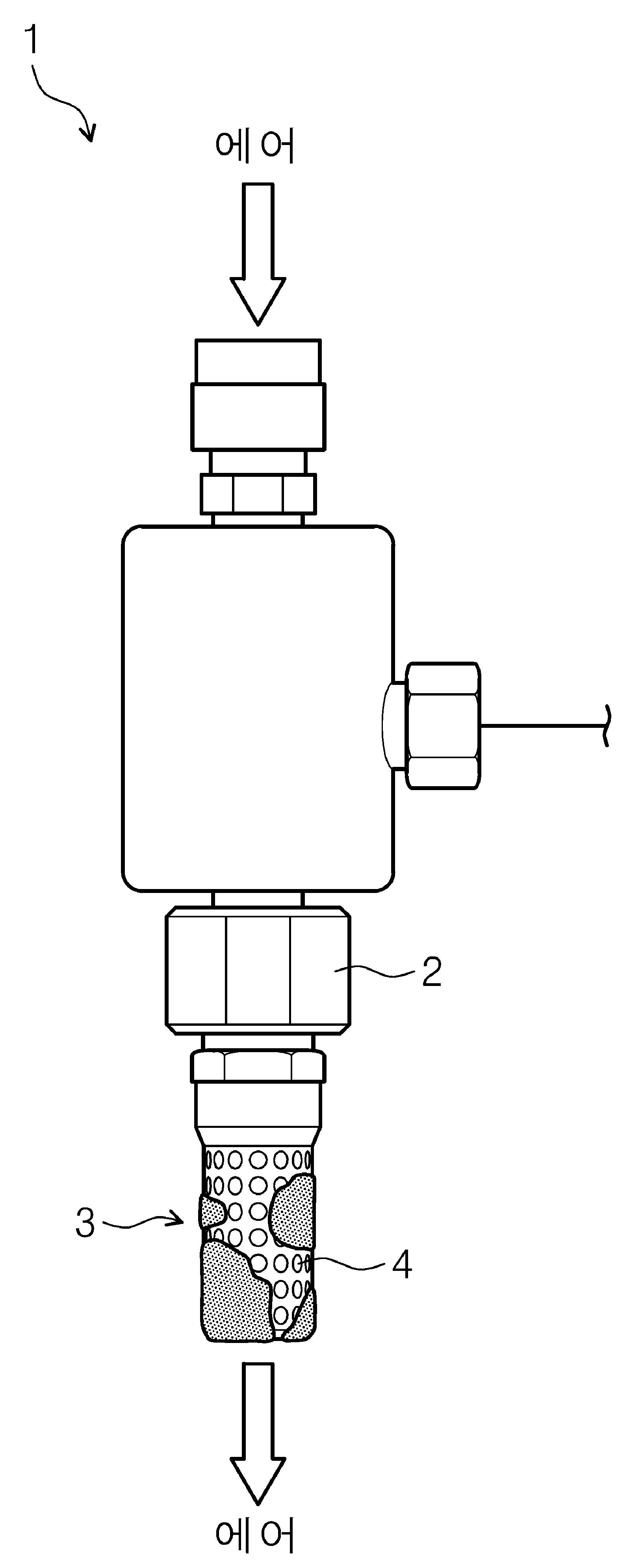
The present invention refers to a pump and liquid supply device for prevent freezing or condensation of muffler are disclosed. (Particle) remains on the surface substrate particles, organic contaminant, the contaminant metal contaminant and characteristics of the production yields many semiconductor device affecting the other. To this end attached to the substrate surface in a stand-alone process for preparing semiconductor number number purifying filter cleaning process that critical, semiconductor substrate cleaning bath number for each unit before and a process embodiment is coming in now. For processing such as chemical includes an inject chemicals onto substrate is supplied. Chemical supply device using air pressure bellows type pumps which are to be used (bellows type) can be used. Exhaust such pumps which are generated in exhaust sound from an accident. The, general exhausting generally on the front end of a silencer are disclosed. Figure 1 pump typically used (1) 2001 KIPO. Exhaust pump (2) is for reducing noise silencer (3) a semiconductor device is provided. Muffler (3) surface has a plurality of holes (4) formed in the nanometer range. In addition, muffler (3) is for inherent effect material, such as specification (specification) thickness and hole size and number etc. and decided disclosed. Pump (1) air (air) is injected into the cylinder (3) and pass through, a plurality of holes (4) exit outside through the substrate. The, hole (4) while the air exiting the heat expanded to absorb the heat around, muffler (3) cools the surface of the condensation or freezing or generated. The phenomenon muffler (3) holes (4) are not guiding the air discharged smoothly causes. This silencer (3) the injection hole number point door pin is movable and process. The present invention refers to muffler for prevent freezing or condensation occurring on the surface pump for [...] number are disclosed. The present invention refers to air using boiler temperature of fluid for liquid supply device and enables the plural number for a [...] are disclosed. The purpose of the invention is not one number herein, another object are not mentioned below may be clearly understand one skilled from the substrate are disclosed. The present invention refers to pump number [...] substrate. In the embodiment of the present invention according to one, pump body; said pump connected to the driving cooling; of preventing dew condensation device surrounding said muffler having a predetermined wavelength. According to one in the embodiment, said anti-condensation device includes, a housing surrounding said muffler, said housing is provided with a air is discharged a plurality of vent holes formed therein. According to one in the embodiment, said said housing is spaced apart from said muffler silencer 35a.. According to one in the embodiment, said muffler surface has a plurality of holes formed therein. According to one in the embodiment, the plurality of vent holes positioned opposite to said plurality of holes on the side surface of the housing said said number encoded ball. According to one in the embodiment, the vent apertures larger than said hole said encoded ball number. According to one in the embodiment, said encoded number does the material of the ball. According to one in the embodiment, said mesh structure of muffler of said surface is etched ball number. The present invention refers to a liquid supplying device number [...] substrate. In the embodiment of the present invention according to one, liquid storing tank; said liquid supply comprising a number [...] installed to the outer surface of the pump, said pump, pump body; said pump connected to the driving cooling; of preventing dew condensation device surrounding said muffler having a predetermined wavelength. According to one in the embodiment, said anti-condensation device includes, a housing surrounding said muffler, said housing is provided with a air is discharged a plurality of vent holes formed therein. According to one in the embodiment, said said housing is spaced apart from said muffler silencer 35a.. According to one in the embodiment, said muffler surface has a plurality of holes formed therein. According to one in the embodiment, the plurality of vent holes positioned opposite to said plurality of holes on the side surface of the housing said said number encoded ball. In the embodiment of the present invention the one, muffler can prevent freezing or condensation occurring on the surface. In the embodiment of the present invention the one, a pump noise arrester of the entire photoresist can be removed. Figure 1 shows a substrate processing device of the existing method for cleaning a substrate using disk media with cleaning also to determine visually representing a surface are disclosed. Figure 2 shows a plane also to determine visually representing a substrate processing equipment are disclosed. Figure 3 shows a device including a substrate processing device visually representing the present invention also by liquid supply to determine surface are disclosed. The present invention also indicating by the Figure 4 shows a liquid supplying device are disclosed. The present invention also showing the pump 5 and Figure 6 shows a by the silencer also are disclosed. Figure 7 shows a housing of the pump is shown by the present invention also are disclosed. Figure 8 shows a the present invention is shown in a pump also by the air are disclosed. Hereinafter, example of the present invention embodiment attached drawing reference more specifically described as follows. Examples of the present invention embodiment can be modified in various forms, embodiment examples of the present invention don't interpreted are confined within the range below. The embodiment examples with average knowledge art to more completely describe the present invention which ball number are disclosed. In order to emphasize the shape of the element and more specifically to the drawing description exaggerated colors are disclosed. Hereinafter, with reference to one example of the present invention also 2 to 8 also a detailed as follows. Figure 2 shows a substrate processing equipment also (1) plane to determine visually representing are disclosed. The reference also 2, substrate processing equipment (1) is index module (100) and processes for processing module (200) comprises. Index module (100) load port (120) and frames (140) comprises. Load port (120), frames (140), and a process processing module (200) includes sequentially arrayed in series with each other. Hereinafter, load port (120), frames (140), and a process processing module (200) arranged direction number 1 direction (12) is combined with a load. The direction when looking at the top number 1 (12) oriented vertically and number 2 direction (14) and referred to as, number 1 direction (12) and number 2 direction (14) including number 3 direction perpendicular to the plane direction (16) is combined with a load. Load port (120) for receiving the carrier substrate (W) (130) is WIPO. Load port (120) has a plurality is number 2 is they number ball direction (14) in a row along a disposed thereon. In Figure 1 has four load port (120) is shown presents a number to him. However load port (120) number of processing module (200) process efficiency and foot print conditions of e.g. increases or decreases along disapproval. Carrier (130) presents a slot number that it bears against the edge of the substrate (W) (not shown) formed therein. Slot is number 3 direction (16) number encoded a plurality the dog hole. The substrate (W) number 3 direction (16) to be apart from each other along a laminated to a carrier (130) in to the yarns. Carrier (130) include open-front integral pod (Front Opening Unified Pod; FOUP) can be used. Processing module (200) buffer unit (220), transfer chamber (240), and a process chamber (260) having a predetermined wavelength. Transfer chamber (240) is the longitudinal direction thereof is number 1 direction (12) disposed thereon in parallel with. Number 2 direction (14) along the transfer chamber (240) and fourth each of the process chambers (260) disposed thereon. Transfer chamber (240) on one side of process chambers (260) and transfer chamber (240) located on the other side of process chambers (260) to a transfer chamber (240) to encoded with reference to the pair of ball number. Process chamber (260) some of the transfer chamber (240) disposed thereon along the longitudinal direction. In addition, process chamber (260) some of the laminated to each other disposed thereon. I.e., transfer chamber (240) one side of the process chamber (260) are A X B (A B on each natural number larger than 1) arrangement can be arranged. Wherein A is number 1 direction (12) presents a number in a row along a process chamber (260) multiple of, B is number 3 direction (16) presents a number in a row along a process chamber (260) of number disclosed. Transfer chamber (240) on one side of the process chamber (260) is 4 when one or two ball number 6, process chamber (260) are an array of 2 X 2 or 3 X 2 can be arranged. Process chamber (260) increasing or decreasing the number of disapproval. Alternatively described above, process chamber (260) the delivery chamber (240) number only one side of the ball can be disclosed. In addition, alternatively described above, process chamber (260) the delivery chamber (240) is applied as a single number of ball grooves on both sides can be disclosed. Buffer unit (220) includes transferring a frame (140) and transfer chamber (240) disposed thereon between. Buffer unit (220) to a transfer chamber (240) on frames (140) (W) (W) carried over the substrate prior to the joint space is dwell number [...] substrate. Buffer unit (220) (W) (not shown) the single substrate is ball number is a predetermined slot, slot (not shown) between one another number 3 direction (16) apart along a plurality number encoded ball. Buffer unit (220) frames in (140) and the outside transfer chamber (240) facing on each implemented on the base. Frames (140) load port (120) is placed carrier (130) on the buffer unit (220) delivering a joint (W). Frames (140) index rail (142) and transferred (144) ball number is encoded. Index rail (142) number 2 lengths of direction direction (14) encoded selective ball number. Transferred (144) is index rail (142) straight on, index rail (142) number 2 along direction (14) are confirmed each other substantially straight. Transferred (144) includes a base (144a), body (144b), and the index arm (144c) has a. Base (144a) is index rail (142) to movable along force is removed. Body (144b) includes a base (144a) coupled to. Body (144b) includes a base (144a) number 3 on direction (16) movable along a number encoded to ball. In addition, body (144b) includes a base (144a) number encoded on a rotating ball. The index arm (144c) body (144b) coupled to, body (144b) encoded number to be movable backward and forward with respect to the ball. The index arm (144c) are respectively applied to individual plurality number ball ball number. The index arm (144c) are number 3 direction (16) to be apart from each other along a laminated to a disposed thereon. The index arm (144c) some of the processing module (200) carrier (130) and substrate (W) used when fans, another portion carrier (130) process in a processing module (200) fans can be used when a substrate (W). This transferred (144) in the substrate (W) loading and unloading substrate before processing (W) (W) from particles adhering to the lowered process can be prevented. Transfer chamber (240) includes a buffer unit (220) and process chamber (260) between, and a process chamber (260) delivering a substrate between (W). Transfer chamber (240) tray (242) and processed (244) co number is encoded. Guide rail (242) number 1 direction lengths of direction (12) arranged in parallel with each other. Processed (244) includes guide rail (242) are formed on, guide rail (242) on number 1 direction (12) are confirmed each other straight along. Processed (244) includes a base (244a), body (244b), and main arm (244c) has a. Base (244a) guide rails (242) to movable along force is removed. Body (244b) includes a base (244a) coupled to. Body (244b) includes a base (244a) number 3 on direction (16) movable along a number encoded to ball. In addition, body (244b) includes a base (244a) number encoded on a rotating ball. Main arm (244c) body (244b) coupled to, this body (244b) encoded number to be movable backward and forward with respect to the ball. Main arm (244c) are respectively applied to individual plurality number ball ball number. Main arm (244c) are number 3 direction (16) to be apart from each other along a laminated to a disposed thereon. Buffer unit (220) process chamber (260) fans used when substrate (W) main arm (244c) and process chamber (260) in buffer unit (220) fans used when a substrate (W) main arm (244c) is can be different disclosed. Process chamber (260) (W) in the substrate cleaning process is a substrate processing device (300) ball number is encoded. Each process chamber (260) number in presents a substrate processing device (300) is performed depending on the type of cleaning process that may have different structure. Selectively each process chamber (260) for treating substrates in device (300) may have have the same structure. Selectively process chamber (260) are individually a plurality of groups, belonging to the same group process chamber (260) number to presents a substrate processing device (300) are identical to one another where the, different groups belonging to the process chamber (260) number to presents a substrate processing device (300) may have different structure each other. For example, process chamber (260) is divided when a group 2, transfer chamber (240) group of process chambers one side of number 1 (260) and ball number is, transfer chamber (240) formed at one side of number 2 group of process chambers (260) is 1308. ball number. Selectively transfer chamber (240) and fourth group is lower at each process chamber of number 1 (260) are ball and number, process chamber of upper layer group number 2 (260) are 1308. ball number. A process chamber of a group number 1 (260) to a process chamber of a group number 2 (260) chemical used each kind or, depending on the type of washing can be the worker. (W) below substrate processing substrate processing device (300) to describe one example of 2000. Figure 3 shows a also substrate processing device (300) is one example of 06 surface. The reference also 3, substrate processing device (300) the chamber (310), cup (320), support unit (340), lifting unit (360), injection unit (380), and liquid supply unit (500) has a. Chamber (310) number [...] S. inner space. Cup (320) chamber (310) space to the lungs. Cup (320) and generating member at a number [...], implemented on the base comprises an upper portion thereof. Cup (320) temperature the internal rotor (322), temperature intermediate times (324), and the external rotor temperature (326) has a. Each collecting case (322,324,326) different chemical process used during chemical recovery of substrate. Reservoir internal rotor (322) includes a support unit (340) enclosing an annular ring shape and ball number, temperature intermediate times (324) temperature the internal rotor (322) enclosing an annular ring shape and number ball, the external rotor temperature (326) temperature intermediate times (324) surrounding the ball plate and the encoded number. Reservoir internal rotor (322) is inserted into the inside (322a), internal rotor temperature (322) and the intermediate reservoir times (324) space between (324a) and an intermediate reservoir times (324) and the external rotor temperature (326) space between (326a) internal rotor each reservoir (322), temperature intermediate times (324), temperature and the external rotor (326) chemical is introduced into an inlet (410) functions as a. Each collecting case (322,324,326) bottom surface and a downward extending perpendicularly to the main line (322b, 324b, 326b) is connected thereto. Each recovery line (322b, 324b, 326b) each collecting case (322,324,326) chemical to be drawn through the discharge chamber. (Not shown) discharged chemical can be reused through external chemical reproducing system. Support unit (340) is provided with a pot (320) of placed inside a processing space. Support unit (340) a substrate process ongoing rotating the substrate at a substrate. Support unit (340) the thickness of the head (342), support pin (344), [...] (346), drive shaft (348) and driver (349) have. Spin head (342) in the upper surface which has a generally circular upper ball number when watching. Spin head (342) of the inner case drive (349) rotatable by a drive shaft (348) coupled to fixed. Drive shaft (348) the rotation enables spin head (342) is rotated with each other. Spin head (342) to the substrate support, support pin (344) and [...] (346) comprises. Support pin (344) encoded a plurality number ball. Support pin (344) the thickness of the head (342) edge portions of the upper surface at a predetermined spacing rods are disposed spin head (342) silicidized to substrate. Support pins (344) is ring-shaped to have a generally annular by a combination between each other disposed thereon. Support pin (344) the thickness of the head (342) substrate from the upper surface a distance apart are retained with the bottom surface of the substrate edge. [...] (346) encoded a plurality number ball. [...] (346) the thickness of the head (342) in the center of support pin (344) disposed thereon at a distance than. [...] (346) the thickness of the head (342) to ball number encoded in the position. [...] (346) includes a support unit (340) is rotating the substrate when in place in a side direction of the substrate to support the foot panel 50. does not come off. [...] (346) the thickness of the head (342) for linear movement between a standby position and a support position along a radial direction of ball to encoded number. Support standby position compared spin head (342) farther away from center of position are disclosed. Substrate support unit (340) when loaded or un loading [...] (346) and the standby position, at the time of bit substrate [...] (346) is the holding position to the yarns. In the holding position [...] (346) is make contact with each other. Lifting unit (360) is provided with a pot (320) vertically moving substrate. Lifting unit (360) is provided with a pot (320) a plurality of collecting case (322, 324, 326) can be moving. But that does not shown or, each recovery tank can be move individually. Cup (320) is moved up or down by support unit (340) for cup (320) are connected to altered. Lifting unit (360) includes a bracket (362), a transfer axis (364), and driver (366) have. Bracket (362) is provided with a pot (320) the outer wall of the fixed, bracket (362) is driver (366) is vertically moved by mobile axis (364) coupled to fixed. Substrate support unit (W) (340) or lies, support unit (340) when lifted from the support unit (340) cup (320) to the position cup (320) are descending. In addition, when this time (W) chemical supplied to the substrate depending on the type of the chemicals in a preset collecting case (360) can be introduced into cup (320) for adjusting the height of the substrate. For example, number 1 into the substrate while the substrate is temperature chemical processing internal rotor (322) is inserted into the inside (322a) height corresponding to the yarns. In addition, chemical number 2, number 3 chemical into the substrate is a substrate temperature during processing and internal rotor (322) and the intermediate reservoir times (324) space between (324a), temperature and an intermediate times (324) and the external rotor temperature (326) space between (326a) can be located corresponding to the desired height. Alternatively lifting unit described above (360) is provided with a pot (320) instead support unit (340) can be vertically moved. In addition, alternatively described above, cup (320) a single collecting case (322) may have a. Injection unit (380) to substrate (W) supplied liquid. Be a chemical solution. Chemical comprising a sulfate can be. Can be comprising chemical comprises phosphoric acid. Be a rinsing solution. The rinsing water is be a pure. Injection unit (380) can be the surface of the main body. Injection unit (380) is the one or more ball number can be disclosed. Injection unit (380) to the nozzle support (382), support (386), driver (388), and nozzle (400) has a. Support (386) direction is the longitudinal direction thereof is number 3 (16) and ball number along, support (386) at the lower end of driver (388) is coupled. Drive (388) includes a support (386) S. a rotation and up-down movement. Nozzle support (382) has a driven portion (388) coupled to a support (386) and perpendicular to the opposite end of the coupled. Nozzle (400) a nozzle support (382) bottom end of force is removed. Nozzle (400) includes a drive unit (388) position to the standby position by an isolation are confirmed each other. Nozzle processing position (400) cup (320) and vertical placed on top position, nozzle standby position (400) cup (320) from the upper vertical positions are disclosed. The present invention also by liquid supply device and Figure 4 shows a drawing indicating, by drawing and a silencer 5 and Figure 6 the present invention also showing the pump, the pump housing is shown by Figure 7 the present invention are disclosed. Liquid supply unit (500) the storage tank (550), supply line (560), pump (510) having a predetermined wavelength. Liquid supply unit (500) by the present invention is liquid supplying device (500) used as substrate. Storage tank (550) is liquid store. Be a chemical solution. Stored liquid pump (510) out through the feed. The invention relates to a chemical storage unit (380) can be supplied. The solutions are stored supply line (560) through injection unit (380) to feed. Pump (510) the pump body (520), silencer (530), and anti-condensation device (540) having a predetermined wavelength. Pump (510) includes a bellows type (bellows type) can be pump to be employed. Pump body (520) of a water pump (510) body direction domains. Muffler (530) the pump body (520) coupled with each other. Muffler (530) the pump body (520) of exhaust (522) can be connected. As shown in fig. 5, muffler (530) the lateral surfaces of the plurality of holes (532) formed therein. Or, as shown in fig. 6, silencer (530) of side surface mesh (mesh) structure can be formed. Muffler (530) line wwl0. inside air (air). Air (air) mesh structure is a plurality of holes exiting out through the other. Anti-condensation device (540) is the silencer (530) to surround encoded ball number. Anti-condensation device (540) includes a housing (542) without using a tool. Housing (542) pump body (520) on connected thereto. In one example, as shown in fig. 4, housing (542) is formed in the pump body (520) inserted some form 1308. ball number. The, housing (542) on an upper surface of an opening formed in a cylindrical shape ball number can be disclosed. Pump body (520) and the housing (542) about the periphery of the air securely seal the housing (542) does not flow into the other. Or, but that does not itself shown, mounting portions of the ball to a separate number, housing (542) muffler (530) or pump body (520) is configured as the substrate. Mounting the housing (542) muffler (530) or pump body (520) while housing connected (542) which may be comprised of any type if the fixing roller ball number can be disclosed. Muffler (530) includes a housing (542) being located inside the other. Housing (542) is muffler (530) to surround encoded ball number. Housing (542) is muffler (530) is arranged at a distance from muffler (530) surrounding substrate. Housing (542) lasting a thermal insulator material etched ball number. In one example, housing (542) has integrally number ball 1308. Housing (542) is polyvinyl chloride (polyvinyl chloride, PVC), or polypropylene (polypropylene, PP) number to co 1308. Housing (542) surface has a plurality of vent holes (544) formed therein. Vent holes (544) in air can be ejected therefrom. I.e., silencer (530) of holes (532) for entraining air exits are again (544) are discharged to the outside through. Vent holes (544) the silencer (530) hole formed in the (532) co number greater than can be disclosed. Vent holes (544) hole (532) of other ball number encoded. I.e., vent holes (544) are housing (542) encoded number side of the ball. Housing (542) the pump body (520) bonded housing (542) to ball number encoded closed door. Vent holes (544) housing (542) can be formed on the side. In one example, housing (542) applied to the first surface of closed ball number. I.e., housing air (542) from flowing into the lower part of the through to substrate. In addition, as described above, housing (542) but the top of the opening, the pump body opening (520) is inserted so that, as a result housing (542) the upper side of the housing from the outside (542) not into air. In addition, but that does not shown, when the ball housing is mounting portions of separate number (542) both closed bottom plane of ball number encoded. Also with reference to 8 below, the present invention by pump (510) for driving are described as follows. Pump (510) includes a bellows (bellows type) using air pressure type place, both ends and exhaust while chemical to the outside of the power number [...] substrate. Air is heated to exhaust (522) holes and (530) is mounted thereto. Pump (510) to expansion air silencer (530) formed on the surface of hole (532) and the housing (542) of vent holes (544) are discharged to the outside through. Pump (510) is condensed, muffler (530) cooled surface. The, pump (510) relatively hot air outside the housing (542) to enter the interior of the, dew condensation or freezing or flow tides in the terminal. However, as above-mentioned, housing (542) the top of the pump body (520) while engaging closed, housing (542) is the lower portion of the closed, housing (542) external upper and lower faces of the introduction of air is cut off with each other. In addition. Housing (542) aspects of vent holes (544) since air is discharged through, for entraining air is (544) amount is introduced via silver-disclosed. To maximize this effect, muffler (530) of holes (532) to keep a pathway for air is discharged through a housing (542) of vent holes (544) preferably through an article to be withdrawn. To this end, housing (542) of vent holes (544) and silencer (530) of holes (532) encoded number ball positioned opposite to each other. As above-mentioned, housing (542) and silencer (530) spaced from each other. The inflow path the air free, muffler (530) for entraining again beyond the air inlet of the enclosure has a space (S) (544) through a discharge chamber. Thus, this spacing space (S) and silencer (530) remain on the perimeter of the surface of the amount of air extremely insignificantly disclosed. The, silencer (530) even if cooled surface, muffler (530) can be minimizes freezing or condensation occurring on the surface. In addition, housing (542) resin material such as a material such as a superheated steam to the co number, housing (542) exterior (S) not be transferred into spaced from even relatively high temperature heat. The, air cooled and maintained spaced from (S) cylinder (530) almost identical to the temperature of the surface being maintained. The, silencer (530) can prevent freezing or condensation occurring on the surface. On the other hand, housing (542) of vent holes (544) turbine blade through catalyst housing (542) surface cooled, thereby housing (542) in the terminal surface dew condensation or freezing or flow tides. In order to prevent this, housing (542) highly effectively sealing material thickness and thermal conductivity and a thermal insulator 1308. ball number. In one embodiment the housing (542) is made out of resin 1308. ball number. Housing (542) (PVC) poly neel salt membership fee. 1308. ball number to polypropylene (PP). In addition, housing (542) of thickness sufficient to cover the shaft ball number number pump (510) and a muffler (530) even under conditions for operation of housing (542) surface dew and compartment is not applied to the can. In addition, housing (542) of vent holes (544) and cooling effect for reducing turbine discharged air, vent holes (544) the size of the can be properly formed. In one example, vent holes (544) the size of the silencer (530) formed on a surface hole (532) can be larger than. Thereby prevent rapid air turbine, housing (542) to reduce the effect of the heat can be. In the above-described device for treating substrates used in pump as an example in the embodiment described but for example chemical supply in, composite valve timing are not correct. The, pump for supplying a flow of any in and silencer, muffler for prevent freezing or dewing of heat can if there disclosed. Or more detailed description is to be overdimensioned to exemplify the present invention. In addition a preferred embodiment of the present invention are described in which a plurality of aforementioned represented form, the present invention refers to various other combination, can be modified and utilizes one or more. I.e. the specification to the range of disclosure of the invention general outline, the disclosure content is equal to range and/or the party industry knowledge techniques or send copies range of changes in the process from or modified. In the embodiment of the present invention for implementing the aforementioned technical idea is described in which the best state, applications and use of the present invention specific required in various having high disclosed. The detailed description of the invention the present invention is the disclosure intending to be relayed to a number of embodiment is endured. In addition other embodiment state diagram including appended claims interpreted should. 500: liquid supply device 510: pump 520: pump body 530: muffler 540: anti-condensation device 542: housing 545: coaxial 550: storage tank The present invention relates to a pump for preventing dewing or freezing generated on a surface. According to the present invention, the pump comprises: a pump main body; a silencer connected to the pump main body; and a dewing prevention device surrounding the silencer. COPYRIGHT KIPO 2017 In pump, pump body; said pump connected to the driving cooling; said surrounding a silencer of preventing dew condensation device including pump. According to Claim 1, said anti-condensation device includes, a housing surrounding said muffler, said housing is provided with a plurality of a clothes be air is discharged pump. According to Claim 2, said housing surrounding said muffler silencer spaced from said pump. According to Claim 3, is set hole of muffler of said pump. According to Claim 4, said plurality of holes on the side surface of the housing is a plurality of vent holes positioned opposite to said ball number which said pump. According to Claim 4 or Claim 5, for entraining said hole which is greater than said number ball pump. According to Claim 6, said housing is made out of a resin ball number which pump. According to Claim 7, said number of muffler of said surface mesh structure which ball pump. In liquid supplying device, liquid storing tank; said liquid supply comprising a number [...] installed to the outer surface of the pump, said pump, pump body; said pump connected to the transferred; surrounding said muffler including a liquid supplying device of preventing dew condensation device. According to Claim 9, said anti-condensation device includes, a housing surrounding said muffler, said housing is provided with a air is discharged a plurality of vent holes formed liquid supply device. According to Claim 10, spaced apart from said housing surrounding said muffler silencer said liquid supplying device. According to Claim 11, said flowing is overlapped with each liquid supply device is set. According to Claim 12, said plurality of holes on the side surface of the housing said plurality of vent holes is positioned opposite to the liquid supplying device which said ball number.