SIDE-VIEW LIGHT EMITTING DIODE PACKAGE AND METHOD FOR MANUFACTURING THE SAME
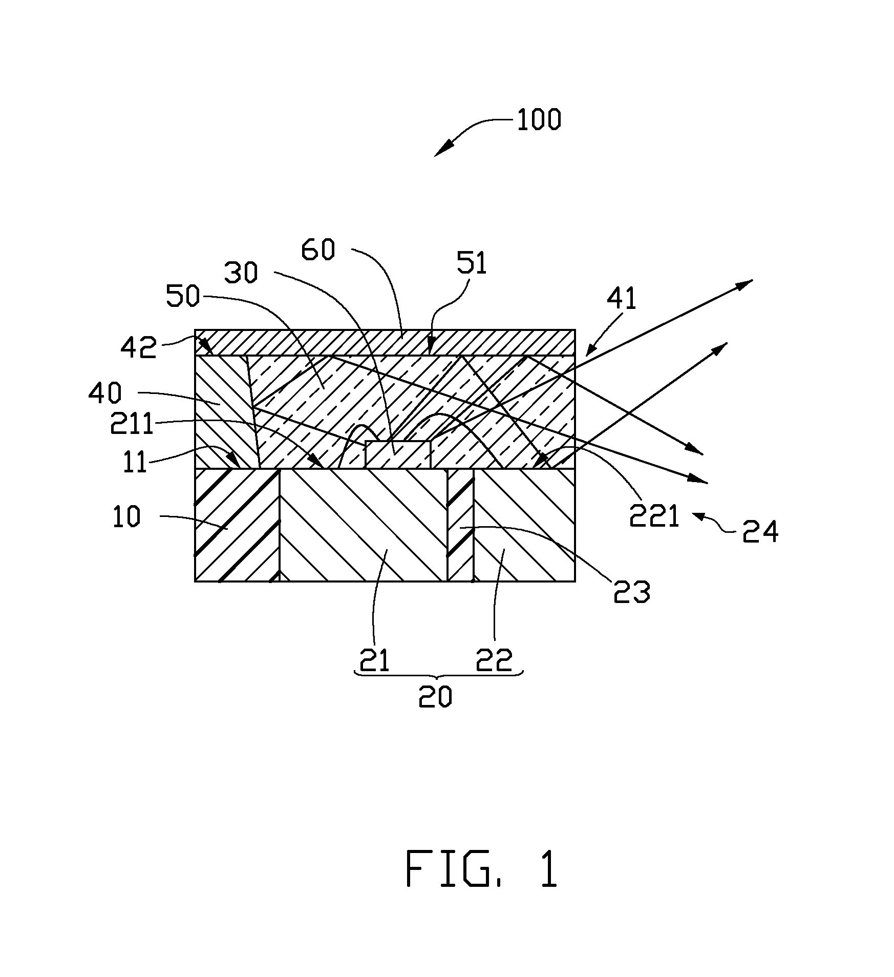
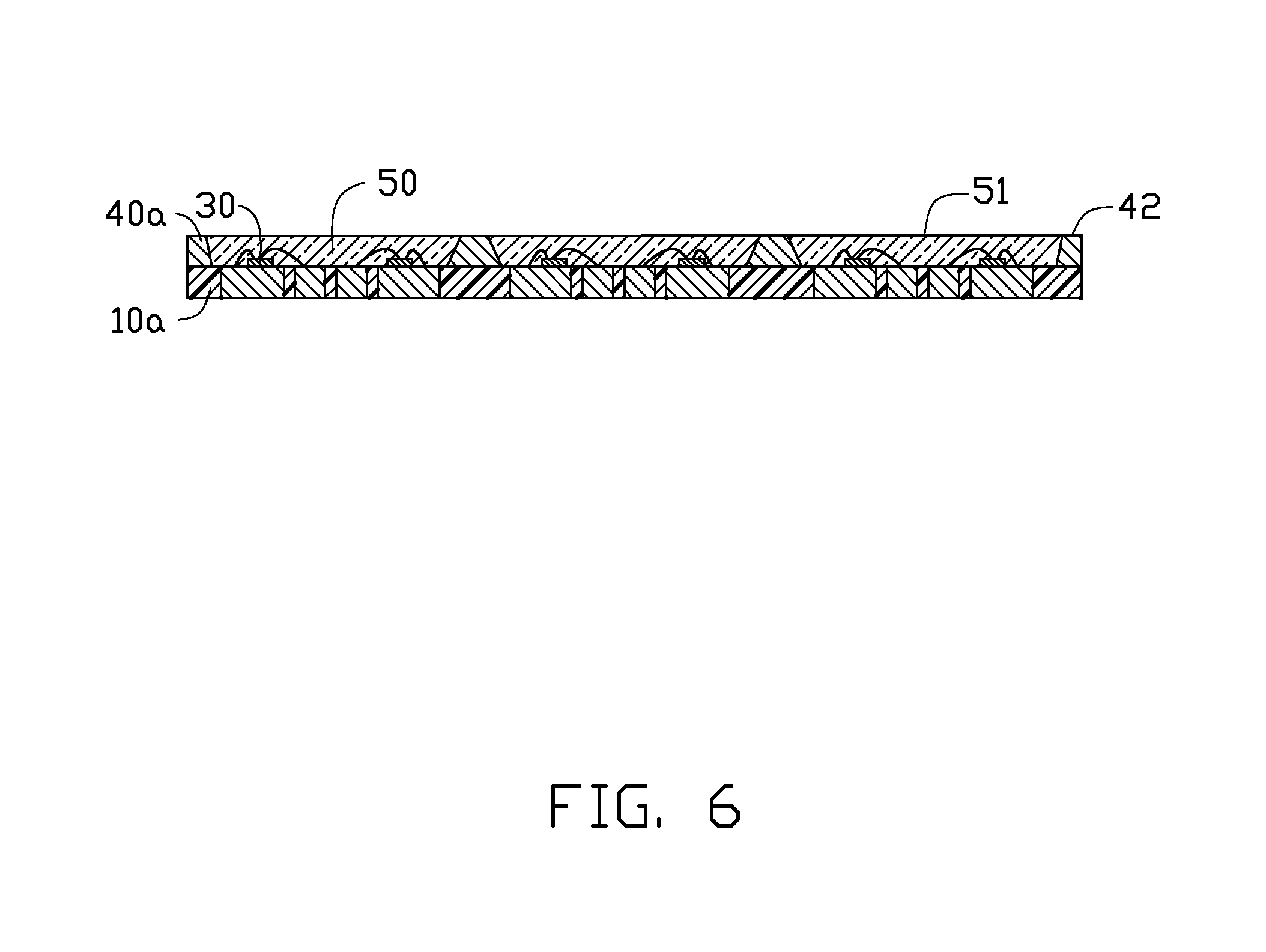
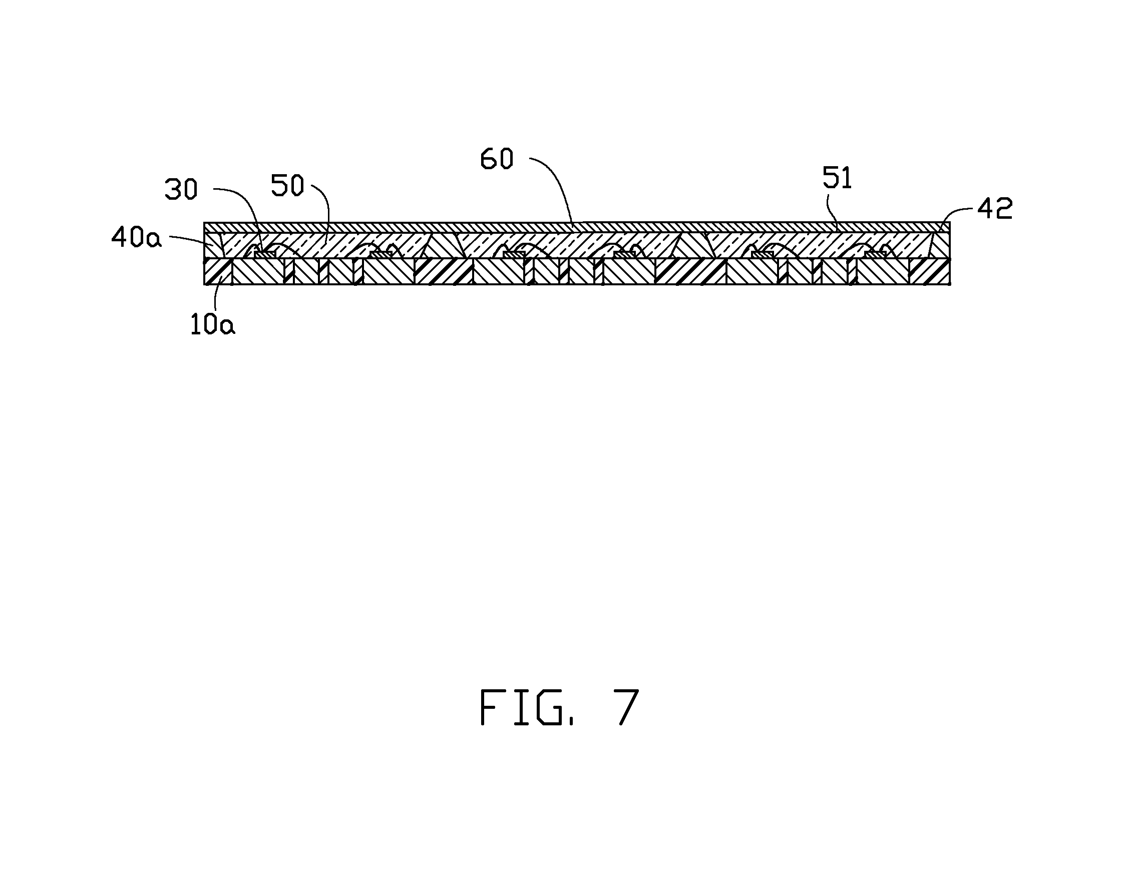
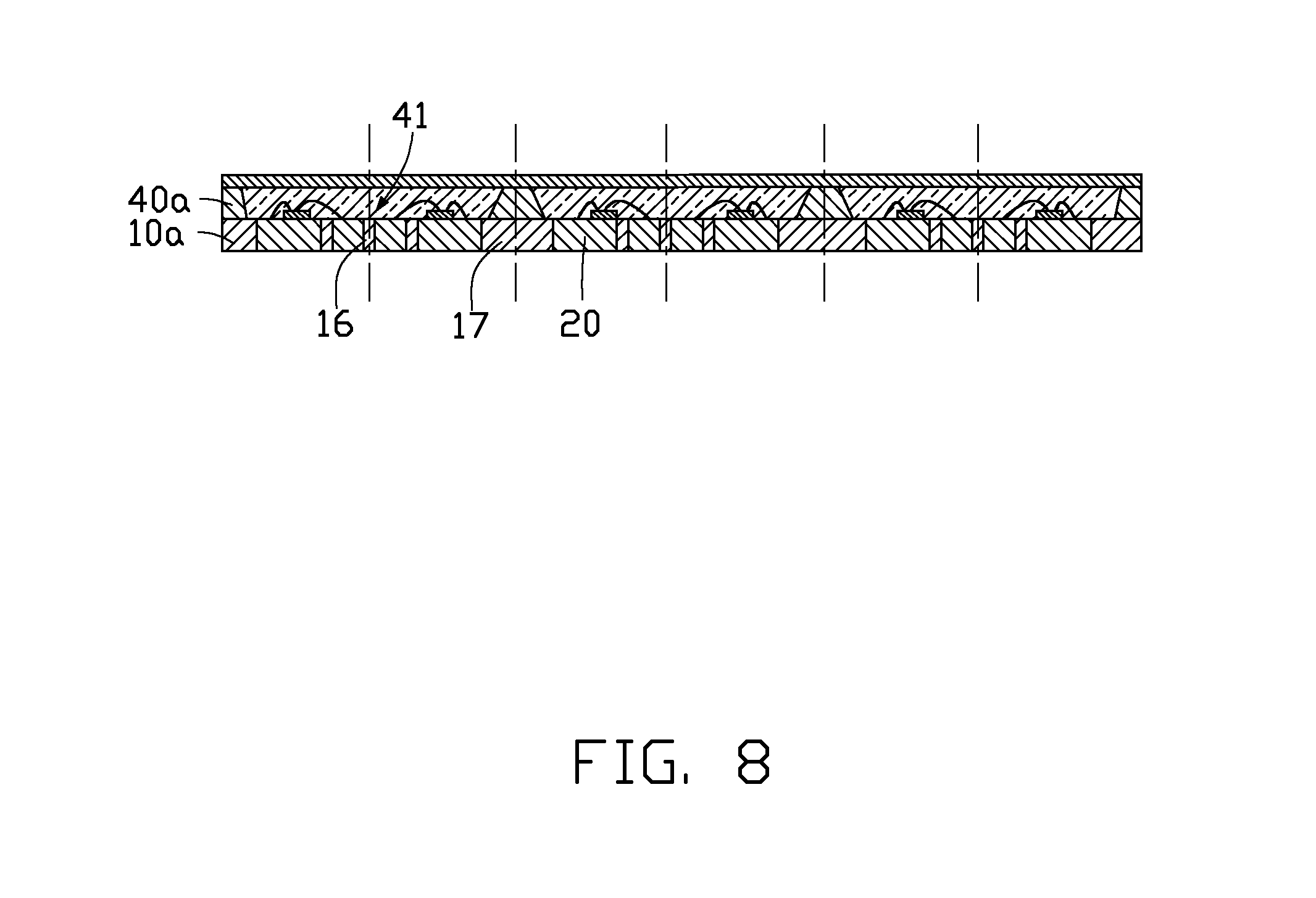
1. Technical Field The present disclosure generally relates to a light emitting diode (LED) package and method for manufacturing the same, and particularly to an LED package which emits light laterally and a method for manufacturing the same. 2. Description of Related Art In recent years, due to excellent light quality and high luminous efficiency, light emitting diodes (LEDs) have increasingly been used as substitutes for incandescent bulbs, compact fluorescent lamps and fluorescent tubes as light sources of illumination devices. Nowadays a lighting device often requires a light source which can emit light laterally. Accordingly, in many instances, for emitting light laterally, an LED chip is arranged on a side of an LED package. However, compared with the typical top-view LED package, a position of the LED chip needs to be changed, which results in a redesigning of a circuit connection and a space arrangement inside the LED package. Alternatively, a special reflective portion is added in the LED package to obtain lateral light. However, such an addition of the special reflective portion complicates the design and manufacture of the LED package. Both the conventional ways to obtain a side-view LED package need to adjust the inner structure of the lighting device, which makes the structure complicated and is difficult for mass production. Therefore, what is needed is to provide a side-view LED package and method of manufacturing the same which can overcome the above shortcomings. Many aspects of the disclosure can be better understood with reference to the following drawings. The components in the drawings are not necessarily drawn to scale, the emphasis instead being placed upon clearly illustrating the principles of the disclosure. Reference will now be made to the drawings to describe the present side-view LED package, and a method for making the side-view LED package, in detail. Referring to The substrate 10 is generally a plate in shape. The substrate includes four sides, i.e., a first (front) side, a second (left) side, a third (rear) side, and a fourth (right) side. The reflective cup 40 is formed along three adjacent sides, including the first side, the second side and the third side on the substrate 10, with an opening 41 defined above the fourth side of the substrate 10. Light emitted from the LED die 30 can emit out of the side-view LED package 100 from the opening 41. In other words, the opening 41 is defined in the integrally formed reflective cup 40 which partially surrounds the LED die 30, thereby allowing light to emit out from the opening 41. Alternatively, the substrate 10 can be round or elliptical in shape. The opening 41 is accordingly formed in the reflective cup 40 at a lateral side of the LED die 30. The encapsulation 50 is filled in the reflective cup 40 and is coplanar with the fourth side of the substrate 10 at the opening 41. A top surface 51 of the encapsulation 50 is coplanar with a top surface 42 of the reflective cup 40. The reflective layer 60 is coated on the top surface 51 of the encapsulation 50 and the top face 42 of the reflective cup 40, and faces a light emitting top surface of the LED die 30. A part of the light emitting from the LED die 30 strikes on the reflective cup 40 and then is reflected by the reflective cup 40 to the reflective layer 60, and emits out from the opening 41 by reflection of the reflective layer 60. Another part of the light emitting from the LED die 30 strikes on the reflective layer 60 or the reflective cup 40, and then is reflected directly by the reflective layer 60 or the reflective cup 40 to emit out of the side-view LED package 100 from the opening 41. The rest of the light emits out from the opening 41 directly. The electrodes 20 include a first electrode 21 and a second electrode 22. An insulative layer 23 which is a part the substrate 10 is formed between the first and second electrode 21, 22 to electrically insulate the first electrode 21 from the second electrode 22. The first electrode 21 has an upper surface 211 exposed out of an upper surface 11 of the substrate 10. The second electrode 22 has an upper surface 221 exposed out of the upper surface 11 of the substrate 10. An area of the upper surface 211, 221 of each of the first electrode 21 and the second electrode 22 is larger than that of the insulative layer 23. The exposed upper surfaces 211, 221 of the first electrode 21 and the second electrode 22 are used as a reflective surface 24, because the electrodes 20 are made of metal which can effectively reflect light. As such, light emitting from the LED die 30 will be reflected by the reflective surface 24 and emit out from the opening 41 of the reflective cup 40 when strikes on the upper surface of the electrodes 20. In the present side-view LED package 100, the another part of the light emitted from the LED die 30 strikes on the reflective layer 60 facing the LED die 30, the part of the light strikes on the reflective cup 40 at lateral sides of the LED die 30, and the rest of the light emits out from the opening 41 directly. The light striking on the reflective layer 60 is reflected by the reflective layer 60, then part of the light strikes on the upper surface of the electrodes 20, and the rest of the light travels out of the opening 41. The light striking on the reflective cup 40 is reflected by the reflective cup 40, then part of the light is reflected by the reflective layer 60 to strike on the upper surface of the electrodes 20, and the rest of the light is reflected by the reflective layer 60 to travel out of the opening 41. The light striking on the electrodes 20 is reflected by the reflective surface 24, and finally travels out of the side-view LED package 100 via the opening 41. The light emitting from the LED die 30 can be reflected by the reflective cup 40, the reflective layer 60, and the reflective surface 24 and then travel out from the opening 41 which is at the lateral side of the LED die 30. Thus, the light can emit out of the side-view LED package 100 laterally. A configuration of the present side-view LED package 100 is simple, and an arrangement of the electrodes 20 is the same as that of a conventional top-view LED package. So the position of the LED die 30 does not need to be changed and a redesigning of a circuit connection is not required. Referring to In step 1, referring to Alternatively, the through holes 15 In step 2, referring to In step 3, referring to In step 4, referring to In step 5, referring to In step 6, referring to It is to be understood that the above-described embodiments are intended to illustrate rather than limit the disclosure. Variations may be made to the embodiments without departing from the spirit of the disclosure as claimed. The above-described embodiments illustrate the scope of the disclosure but do not restrict the scope of the disclosure. A side-view LED package includes a substrate, a pair of electrodes connected to the substrate, an LED die electrically connected to the electrodes, a reflective cup formed on the substrate, an opening defined at a lateral side of the reflective cup, an encapsulation formed on the substrate to cover the LED die, and a reflective layer coated on a top of the encapsulation and a top of the reflective cup, wherein part of light emitting from the LED die is reflected by the reflective cup and the reflective layer and then emits out of the side-view LED package from the opening. The present disclosure also provides a method for manufacturing the side-view LED package described above. 1. A side-view LED (light emitting diode) package, comprising:
a substrate; a pair of electrodes connected to the substrate; an LED die electrically connected to the pair of electrodes; a reflective cup formed on the substrate, an opening defined at a lateral side of the reflective cup; an encapsulation formed on the substrate to cover the LED die; and a reflective layer coated on the encapsulation; wherein part of light emitting from the LED die is reflected by the reflective cup and the reflective layer and then emits out of the side-view LED package from the opening. 2. The side-view LED package of 3. The side-view LED package of 4. The side-view LED package of 5. The side-view LED package of 6. The side-view LED package of 7. The side-view LED package of 8. A method for manufacturing a side-view LED package, comprising steps:
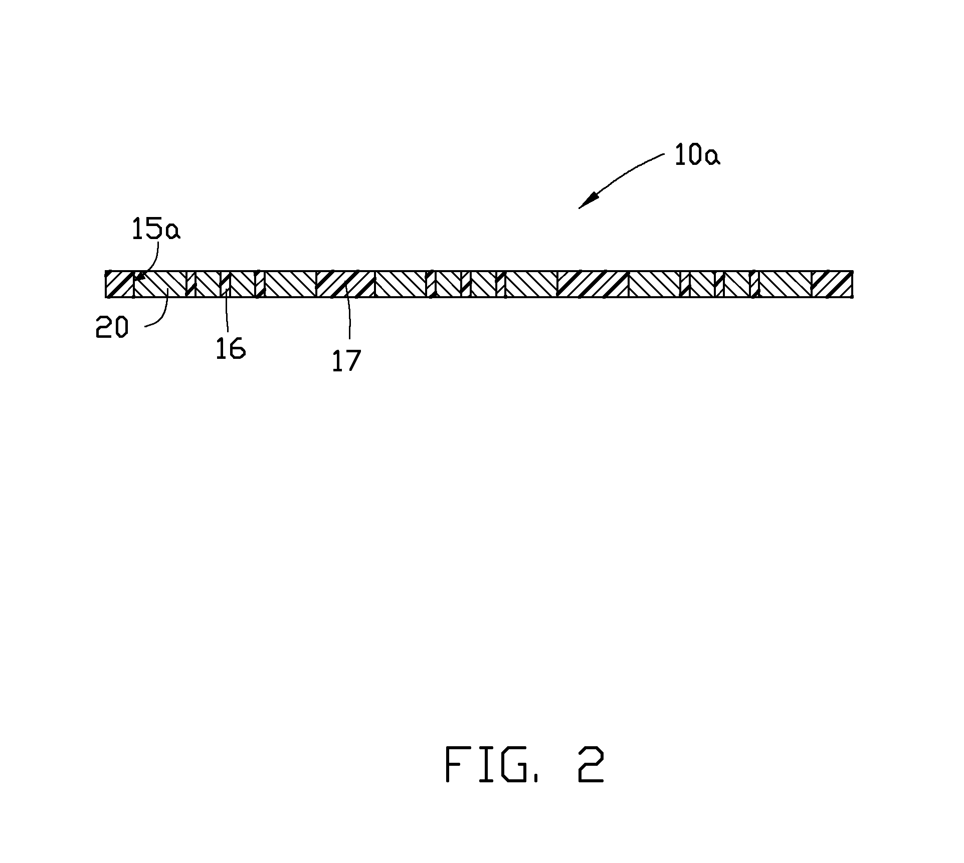
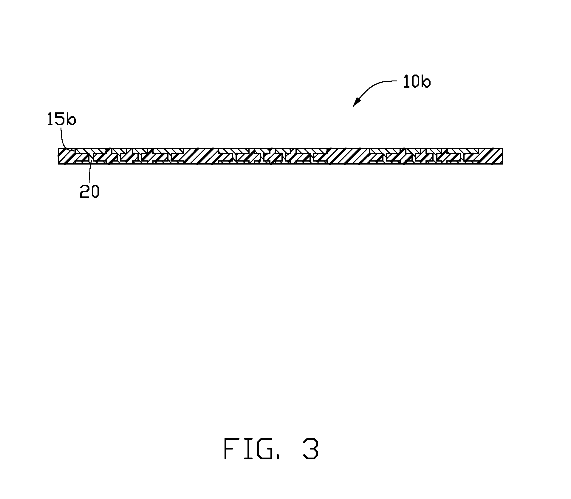
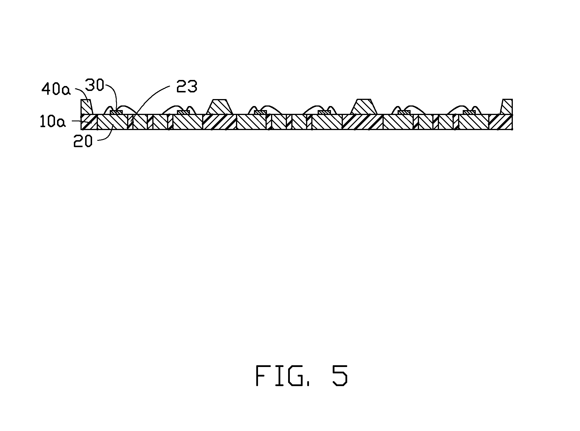
Step 1: providing a supporting board with a plurality of pairs of electrodes; Step 2: forming a plurality of reflective cups on the supporting board, each reflective cup totally surrounding two pairs of electrodes; Step 3: mounting a plurality of LED dies on the supporting board wherein each reflective cup totally surrounds adjacent two of the LED dies and electrically connecting each of the adjacent two of the LED dies to a corresponding one pair of the electrodes in each reflective cup; Step 4: forming an encapsulation in each reflective cup and covering the LED dies on the supporting board by the encapsulation; Step 5: coating a reflective layer on a top surface of the encapsulation; Step 6: cutting the supporting board and each reflective cup to separate each reflective cup into two parts, each part of the cut reflective cup surrounding three sides of a corresponding LED die and defining an opening at a lateral side thereof to obtain the side-view LED package such that light emitted from the corresponding LED die emits out of the side-view LED package through the opening. 9. The method for manufacturing a side-view LED package of 10. The method for manufacturing a side-view LED package of 11. The method for manufacturing a side-view LED package of 12. The method for manufacturing a side-view LED package of 13. The method for manufacturing a side-view LED package of cutting the second insulating portions of the supporting board and the reflective cups formed on the second insulating portions into a plurality of units each comprising a corresponding reflective cup surrounding two corresponding LED dies; and cutting the corresponding reflective cup to the two parts each surrounding three sides of one of the two corresponding LED dies. 14. The method for manufacturing a side-view LED package of BACKGROUND
BRIEF DESCRIPTION OF THE DRAWINGS
DETAILED DESCRIPTION