SUBRING FOR SEMICONDUCTOR DIES
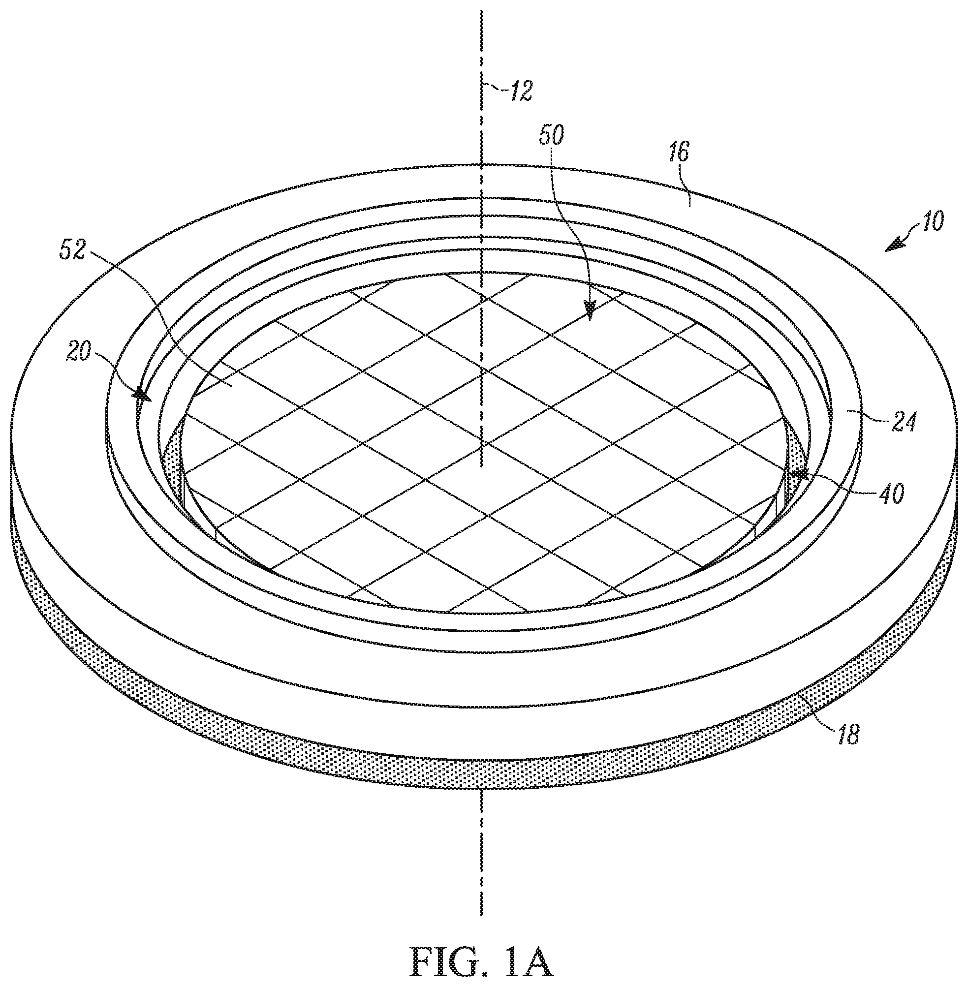
The present disclosure relates generally to semiconductors and, more specifically, relates to a subring for clamping and expanding tape holding a partitioned semiconductor wafer. In one example, a subring for holding tape connected to semiconductor dies and spanning a passage in a frame having a first diameter includes a base centered on and extending about an axis. An opening extends through the base and has a second diameter at least as large as the first diameter. A projection extends from the base to ends positioned on opposite sides of the base. The projection is adapted to clamp the tape to the frame and adapted to prevent relative movement between the tape, the subring, and the frame. In another example, a system for holding tape connected to semiconductor dies includes a frame having opposing first and second surfaces and a passage extending from the first surface to the second surface. The passage has a first diameter and the tape is attached to the second surface to align the dies with the passage. A subring formed from sections includes a base. An opening extends through the base and has a second diameter at least as large as the first diameter. A projection extends from the base to ends positioned on opposite sides of the base. The projection is adapted to clamp the tape in an expanded condition to the frame and adapted to prevent relative movement between the tape, the subring, and the frame. A cap is positioned over the projection for holding the sections together and adapted to clamp the tape between the cap and the projection. In another example, a method for holding tape connected to semiconductor dies includes securing the tape to a first surface of a frame having a passage with a first diameter such that the dies are aligned with the passage. Sections of a subring are inserted through the passage to expand the tape and move the dies through the passage to a position axially spaced from a second surface of the frame opposing the first surface. The sections are assembled into the subring such that the expanded tape is clamped between the subring and the frame. The assembled subring has an opening with a second diameter at least as large as the first diameter of the passage. A chuck is passed through the opening and the passage to further expand the tape and space the dies a predetermined distance from one another. One of the dies is picked from the expanded tape and electrically connected to leads. Other objects and advantages and a fuller understanding of the invention will be had from the following detailed description and the accompanying drawings. The present disclosure relates generally to semiconductors and, more specifically, relates to a subring for clamping and expanding tape holding a partitioned semiconductor wafer. Tape 40 is secured to the second surface 18 of the frame 10. The tape 40 has the same footprint as the frame 10 and therefore spans and covers the passage 20. The tape 40 is made from, for example, a polyvinyl chloride, polyolefin or polyethylene backing material with an adhesive to secure the tape to the frame 10. The adhesive bond can be broken with ultraviolet light or can be a pressure adhesive. The tape 40 can have a thickness of, for example, about 75 to 160 μm. The tape 40 is configured to be flexible and elongate without tearing. A surface 42 of the tape 40 has a periphery 44 abutting and securely connected to the second surface 18 of the frame 10. The remainder of the surface 42 is exposed through the passage 20. A wafer 50 is adhered to the surface 42 of the tape 40 and positioned within the passage 20 of the frame 10. The wafer 50 is therefore axially aligned with the passage 20. The wafer 50 can be circular and has a second diameter Φ2smaller than the first diameter Φ1of the passage 20. The second diameter Φ2can be about 200-300 mm. The wafer 50 is formed from one or more semiconductor materials used in making electronic components, such as part of an integrated circuit. The wafer 50 is provided on the tape 40 after undergoing a wafer dicing process, e.g., scribing, mechanical sawing or laser cutting such as Mahoh dicing. That said, the wafer 50 shown in Referring to The subring 80 includes a planar base 84 having opposing first and second surfaces 86, 88. The surfaces 86, 88 can extend parallel to one another. An opening 90 extends along the axis 82 from the first surface 86 to the second surface 88. The opening 90 has a third diameter Φ3at least as large as the first diameter Φ1of the passage 20 in the frame 10, e.g., at least 350 mm. A projection 100 extends transversely from the base 84. In one example, the projection 100 extends perpendicular to the base 84. The projection has a first end 102 and a second end 104 located on opposite sides of the base 84. The first end 102 terminates at a curved or rounded surface 106. The second end 104 terminates at a curved or rounded surface 108. The surfaces 106, 108 can have any rounded shape, e.g., arcuate, hemispherical, oval parabolic, etc. As shown in The sections 80 In this configuration, the tape 40 can also extend radially inward over the projection 24 (when present) on the frame 10. Regardless, the tape 40 passes entirely through the passage 20 to the periphery 44. The projections 24, 100 cooperate to hold the tape 40 in the expanded condition by maintaining tension on the tape 40 and preventing relative movement between the tape and the frame 10/subring 80. It will be appreciated that when the projection 24 on the frame 10 is omitted the projection 100 alone would maintain tension on the tape 40 and prevent relative movement therebetween. In any case, once the subring 80 is in place and the tape 40 elongated, a cap 120 is positioned over the projection 100 to maintain the sections 80 The curved or rounded shape of the surfaces 106, 108 helps prevent tearing of the tape 40. In particular, the surfaces 106, 108 are configured to provide atraumatic contact between the projection 100 and the tape 40 while adequately preventing relative movement therebetween to maintain tension in the tape. In an alternative configuration shown in When the sections 80 In either construction of the frame 10, once the cap 120 is in place, a chuck 130 is used to further expand the tape 40 (see Since the frame 10 and subring 80 are fixed in place and hold the periphery 44 of the tape 40, the tape expands and elongates in the directions S2. The dies 52 are fixed to the tape 40 and, thus, this stretching causes the dies to spread apart from one another in the directions S2, thereby further increasing the gaps 54 therebetween. In one example, the gaps 54 are configured to allow a die picking device (not shown) to individually pick the dies 52 off the tape 40 without affecting the surrounding dies. In current die picking operations, the die-to-die gap is small enough that there is a risk that picking one die will result in damage to one or more of the surrounding dies. To this end, the tape adhered to the frame and die has a finite ability to elongate. As a result, the expansion process—while increasing the die-to-die gap—can be insufficient for adequately spacing the dies apart from one another. Moreover, with the semiconductor industry moving towards smaller dies, the problem is exacerbated and space is at a premium. When the die size shrinks, the die-to-die gap following partitioning and expansion shrinks due to the same stretched area of tape being used to accommodate more dies. This can increase the incidence of die-to-die collision and/or chipping. The subring 80 is advantageous for having an increased diameter to allow for more expansion of the tape 40, thereby increasing the gaps 54 between the dies 52. In current designs, the subring attaches to the inner edge of the frame adjacent the passage. This reduces the effective diameter of the frame as the chuck passing therethrough is sized by the smallest diameter passage it must pass through. In other words, the chuck has to have a smaller diameter in current subring constructions to pass through the smaller passage of the subring and expand the tape. This reduces the extent to which the tape can be expanded. On the other hand, the subring 80 attaches to the frame 10 a spaced distance from the passage 20 and has a passage diameter Φ3at least as large as the passage diameter Φ1in the frame. Consequently, the chuck 130 can be sized to approximate the full diameter Φ1of the passage 20, which allows the same sized tape to be expanded a greater degree, e.g., up to about 30% greater, than with existing frames. The excess expansion can be distributed amongst the die gaps 54 to thereby increase the average die-to-die gap and help reduce breakage and collision during picking. Along the same lines, using the subring 80 described herein will allow smaller dies to be formed from the wafer 50 using the Mahoh laser saw. The Mahoh saw has a higher yield than mechanical saws and is cheaper to operate. The Mahoh saw also allows for scribe reductions and can reduce the amount of semiconductor material needed to form the smaller dies by reducing waste. The subring described herein is also advantageous because it can be formed from a more durable material than existing subrings. In current designs, the subring is typically formed from a metal ring with a resin component where the subring engages the tape. This resin, however, can wear over time and reduce the clamping efficacy of the subring. The curved surfaces of the subring, however, can be made from the same material as the rest of the subring and maintain clamping ability without wearing. The curved surfaces also have atraumatic engagement with the tape. What have been described above are examples of the present invention. It is, of course, not possible to describe every conceivable combination of components or methodologies for purposes of describing the present invention, but one of ordinary skill in the art will recognize that many further combinations and permutations of the present invention are possible. Accordingly, the present invention is intended to embrace all such alterations, modifications and variations that fall within the spirit and scope of the appended claims. A subring for holding tape connected to semiconductor dies and spanning a passage in a frame having a first diameter includes a base. An opening extends through the base and has a second diameter at least as large as the first diameter. A projection extends from the base to ends positioned on opposite sides of the base. The projection is adapted to clamp the tape to the frame and adapted to prevent relative movement between the tape, the subring, and the frame. 1. A subring for holding tape connected to semiconductor dies and spanning a passage in a frame having a first diameter, comprising:
a base; an opening extending through the base and having a second diameter at least as large as the first diameter; and a projection extending from the base to ends positioned on opposite sides of the base, the projection being adapted to clamp the tape in an expanded condition to the frame and adapted to prevent relative movement between the tape, the subring, and the frame. 2. The subring of 3. The subring of 4. The subring of 5. The subring of 6. The subring of 7. The subring of 8. The subring of 9. A system for holding tape connected to semiconductor dies, comprising:
a frame having opposing first and second surfaces and a passage extending from the first surface to the second surface, the passage having a first diameter and the tape being attached to the second surface to align the dies with the passage; a subring formed from sections and comprising:
a base; an opening extending through the base and having a second diameter at least as large as the first diameter; and a projection extending from the base to ends positioned on opposite sides of the base, the projection being adapted to clamp the tape in an expanded condition to the frame and being adapted to prevent relative movement between the tape, the subring, and the frame; and a cap positioned over the projection for holding the sections together and being adapted to clamp the tape between the cap and the projection. 10. The system of 11. The system of 12. The system of 13. The system of 14. The system of 15. The system of 16. A method of forming an integrated circuit, comprising the steps of:
providing holding tape connected to semiconductor dies; securing the tape to a first surface of a frame having a passage with a first diameter such that the dies are aligned with the passage; inserting sections of a subring through the passage to expand the tape and move the dies through the passage to a position axially spaced from a second surface of the frame opposing the first surface; assembling the sections into the subring such that the expanded tape is clamped between the subring and the frame, the assembled subring having an opening with a second diameter at least as large as the first diameter of the passage; passing a chuck through the opening and the passage to further expand the tape and space the dies a predetermined distance from one another; picking one of the dies from the expanded tape; and electrically connecting leads to the die. 17. The method of 18. The method of 19. The method of 20. The method of TECHNICAL FIELD
SUMMARY
BRIEF DESCRIPTION OF THE DRAWINGS
DETAILED DESCRIPTION