Probe with a Removable Tip
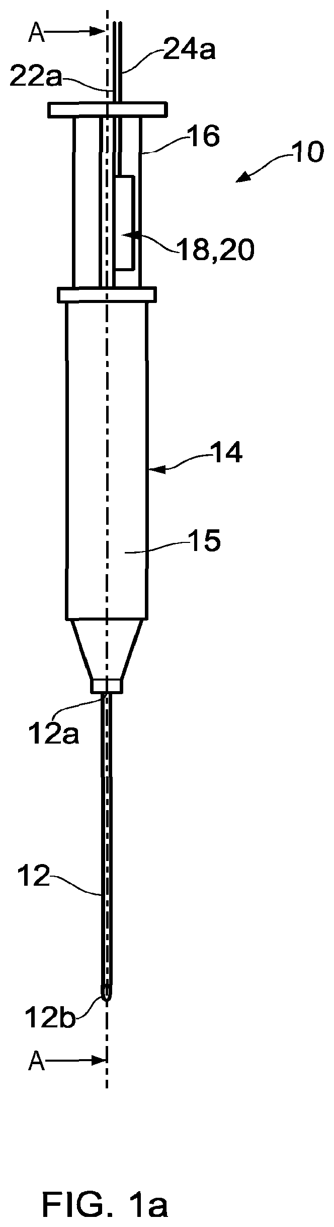
During medical examination of a tissue sample it can be beneficial to identify the tissue type and/or disease state thereof. For example, when cancer is suspected, a patient may have a tumour removed or biopsied and sent for histopathology analyses. Conventional handling involves the tissue undergoing fixation, staining with dyes, mounting and then examination under a microscope for analysis. Typically, the time taken to prepare the specimen is of the order of one day. The pathologist will view the sample and classify the tissue as malignant or benign based on the shape, colour and other cell and tissue characteristics. The result of this manual analysis depends on the choice of stain, the quality of the tissue processing and staining, and ultimately on the quality of education, experience and expertise of the specific pathologist. Thus, conventional tissue examination can be surgically invasive, time consuming and the accuracy of a diagnosis may be heavily reliant on human judgement. According to a first aspect of the invention, there is provided a probe comprising: an elongate conduit for piercing human tissue, the elongate conduit comprising a first opening and a second opening; a wave coupling for transmitting electromagnetic radiation from an energy source into the conduit and/or transmitting electromagnetic radiation from the conduit to a receiver. Thus, a probe according to this aspect includes a conduit, such as a needle, via which electromagnetic radiation can be used for examining a tissue sample. The conduit is arranged and configured such that it may easily be inserted into human tissue and as such the probe can be used to test subcutaneous tissue and/or fluid. The probe can be coupled to a receiver that can be used to analyse the electromagnetic radiation returned from the sample through the conduit. The probe may comprise a carriage for moving an element of the wave coupling between a first, or deployed, condition and a second, or retracted, condition. A portion, such as the tip, of the wave coupling element may be closer to the second opening of the conduit when the wave coupling element is in the deployed condition than it is when wave coupling element is in the retracted condition. Thus, a probe according to such an embodiment enables the position of the tip or other portion of the wave coupling element to be varied. As such, the tip or other portion may be stowed within the conduit during insertion of the conduit into human tissue or the like, so as to reduce the likelihood of the tip being damaged or coming into contact with subcutaneous fluid or tissue which may impair the wave coupling efficiency of the element. Once the conduit has been inserted to a measurement depth the wave coupling element can be moved to the deployed condition for testing. The tip or other portion of the wave coupling element may be at, or adjacent, the second opening of the conduit when the wave coupling element is in the deployed condition. Thus, a probe according to such an embodiment enables the tip of the wave coupling element to be moved to a position in which it is adjacent the tissue at the insertion depth of the conduit. This may improve the testing accuracy of the probe relative to an embodiment where the tip of the element is significantly spaced from the target tissue because the wave coupling transmits the electromagnetic radiation substantially all of the way to the target tissue. The tip or other portion of the wave coupling element may be spaced from second opening of the conduit when the wave coupling element is in the retracted condition. For example, the tip may be spaced from the second opening by at least: one tenth; one eighth; one quarter; a half; three quarters; or the entire length of the conduit. Thus, a probe according to such an embodiment enables the tip to be spaced from the tissue insertion end i.e. the second opening of the conduit. Increasing the spacing can provide a more efficient buffer between the second opening and the tip of the wave coupling element. However, there may be a trade-off between providing a suitable buffer spacing and enabling the tip to easily reach a target location, such as the second opening of the conduit. The wave coupling element may comprise a waveguide. The wave coupling element may comprise a plurality of waveguides. A waveguide may comprise optical fibre. The carriage may comprise a plunger of a syringe to which the conduit is coupled. Thus, a probe according to such an embodiment may conveniently make use of a syringe plunger to act as the carriage. The body of the syringe provides a convenient structure to which to attach the conduit. The probe may include a pressure modifier arranged in fluid communication with the first opening of the conduit, the pressure modifier being operable to change the pressure within the conduit. In some embodiments the pressure modifier may comprise a pump. Thus, a probe according to such an embodiment includes a pressure modifier which can be used to modify the pressure at the first opening of the conduit to draw fluid into the conduit or expel fluid from the conduit. In embodiments where a tip, or other portion, of a wave coupling element is arranged to be moved to the second opening, it is advantageous to be able to expel fluid, such as saline solution, from the conduit because this may clear the passageway between the tip of the wave coupling element and the target tissue of subcutaneous tissue and fluid that may otherwise inhibit the passage of electromagnetic radiation. In any embodiments which include a pressure modifier, the pressure modifier may be used to administer a therapeutic drug, anaesthetic or the like to a test subject via the conduit. In embodiments where fluid is to be tested, it is advantageous to be able to draw the test fluid into the conduit. The pressure modifier may comprise a plunger of a syringe to which the conduit is coupled. Thus, a probe according to such an embodiment may conveniently make use of a syringe plunger to act as the pressure modifier. The body of the syringe provides a convenient structure to which to attach the conduit. A portion of the wave coupling element which enters the conduit may include a stiffening support, such as a metal or hard plastics coating. The pressure modifier may be arranged to reduce the pressure within the conduit. The wave coupling may include a lens arranged to focus electromagnetic radiation into the conduit. The conduit may include a reflective layer or region. The reflective region may provide a number of advantages: it may increase the transmission of electromagnetic radiation along the length of the conduit; it may increase the path length and/or collection efficiency of electromagnetic radiation in fluid within the conduit, which may in some embodiments improve the collection efficiency of Raman emission; and it may reduce the likelihood the electromagnetic radiation escaping laterally from the conduit. Thus, a probe according to such an embodiment may be more accurate and/or sensitive than a system which includes optical fibre alone. The conduit may comprise a hypodermic needle. The energy source may comprise a light source, such as a laser. The electromagnetic radiation may be within the range of ultraviolet to infrared. In any embodiment of the invention including optical fibre, the fibre may have a diameter of 300 μm or less, preferably 200 μm or less and advantageously 150 μm or less. The receiver may comprise a spectroscopic detector, such as a detector arranged to detect Raman spectra. The probe may comprise a body portion and a tip portion arranged to be removably coupled to body portion, wherein the elongate conduit is associated with the tip portion. Thus, the tip portion, which includes the elongate conduit and in use is likely to be contaminated by test tissue or test fluid, can be uncoupled from the body portion of the probe. As such, the tip portion may be discarded following a single use, but the body portion may be retained for subsequent use. The wave coupling may include one or more wave manipulation modules associated with the body portion. Thus, relatively expensive components of the probe such as the wave manipulation modules may be associated with the reusable portion of the probe. The body portion may include a first wave coupling interface and the tip portion may include a second wave coupling interface, the first and second wave coupling interfaces being arranged to provide wave communication between the first and second portions of the wave coupling when the tip portion is coupled to the body portion. Thus, the probe may provide an efficient wave interface between the body portion and the tip portion. The carriage may comprise a body carriage associated with the body portion and a tip carriage associated with the tip portion, the body and tip carriages being arranged to be removably coupled to one another. Thus, part of the carriage may be reusable. In some embodiments, wave manipulation modules, such as light manipulation modules, may be associated the reusable part of the carriage. A portion of the pressure modifier which is arranged to be in fluid communication with the elongate conduit may be associated with the tip portion. Thus, part of the pressure modifier may be reusable. According to a second aspect of the invention, there is provided an optical spectroscope including a probe according to the first aspect. The optical spectroscope may comprise a Raman or fluorescence spectroscope. According to a third aspect of the invention, there is provided a method of testing a tissue or fluid sample comprising the steps of: inserting the conduit of a probe according to the first aspect into the tissue of a test subject; and either transmitting electromagnetic radiation to the tissue or fluid sample via the wave coupling or transmitting electromagnetic radiation from the tissue or fluid sample to a receiver via the wave coupling. The method may comprise moving an element of the wave coupling, such as the tip thereof, from a retracted condition to a deployed condition once the conduit has been inserted into the tissue of the test subject. The method may comprise modifying the pressure at the first opening of the conduit while the probe is inserted in the tissue of the test subject to expel fluid into the test subject or to draw fluid from the test subject into the conduit. The method may comprise the step of administering a therapeutic drug, anaesthetic or the like to the test subject via the conduit. Embodiments of the invention will now be described with reference to the accompanying drawings, in which: The probe 10 according to embodiments of the invention enables subcutaneous tissue to be tested using spectroscopy, preferably Raman spectroscopy. As will be understood, when exciting optical energy of a single wavelength interacts with a molecule, the optical energy scattered by the molecule may contain small amounts of optical energy having wavelengths different from that of the incident exciting optical energy. This is known as the Raman effect. The wavelengths present in the scattered optical energy are characteristic of the structure of the molecule, and the intensity of this optical energy is dependent on the concentration of these molecules. Thus, the identities and concentrations of various molecules in a substance can be determined by illuminating the substance with energy of a single wavelength and then measuring the individual wavelengths, and their intensities, in the scattered optical energy. Raman spectroscopy provides a means for obtaining similar molecular vibrational spectra over optical fibres using visible or near infrared light that is transmitted by the optical fibres without significant absorption losses. In Raman spectroscopy, monochromatic light is directed to a sample and the spectrum of the light scattered from the sample is determined. It should however be noted that a probe according to embodiments of the invention may be used with any suitable receiver or detector, such as a spectroscopic detector arranged to measure fluorescence or elastic scattering. The probe 10 generally comprises an elongate conduit 12 which is arranged to pierce human tissue, a wave coupling 18, 20, 22 The elongate conduit 12 has a first opening 12 The wave coupling 18, 20, 22 As will be appreciated, the exact configuration of the wave coupling according to embodiments of the invention will depend on factors such as the type of electromagnetic radiation used, the target sample and the type of receiver used. In embodiments of the invention the wave coupling may comprise any suitable waveguides and manipulation modules. In some embodiments the probe may include just an excitation path or just a return path, but not both. Thus, two probes could be used together, with one providing the excitation radiation and the other transmitting the radiation from the sample to the receiver. This may enable the probes to be used for spatially offset Raman spectroscopy and/or transmission measurements. In the illustrated embodiment, the wave coupling element 22 In other embodiments, the wave coupling element may comprise any part of the wave coupling. In the illustrated embodiment, the carriage 16 for moving the wave coupling element 22 The syringe 14 defines a pressure modifier arranged in exclusive fluid communication with the first opening 12 In other embodiments which include a carriage for moving one or more portions of the wave coupling, the carriage may be any suitable part arranged to move relative to the conduit of the probe and should the embodiment also include a pressure modifier, the carriage need not also serve as the pressure modifier. For example, the plunger 16 of the illustrated embodiment may include an opening, or one way valve, through the piston seal 16 In other embodiments which include a pressure modifier arranged to change the pressure within the conduit 12, the pressure modifier may be any suitable part arranged to increase or decrease the pressure at an opening of the probe 12. Should an embodiment include a carriage and a pressure modifier, the pressure modifier need not also serve as the carriage. For example, the optical coupling may be coupled to the syringe body of the illustrated embodiment and the plunger 16 may move relative to both the syringe body and optical coupling as is the case with the embodiment described with reference to Referring additionally to Light from the sample is collected and collimated by a GRIN collecting lens 20 In other embodiments, any suitable electromagnetic radiation may be used as the excitation signal. It should be also noted that, while GRIN lenses have been described, any suitable lens type may be used in the optical coupling of other embodiments. In the illustrated embodiment, the tip 22 As shown in Referring additionally to The probe 50 is arranged for a fluid sample to be tested within the chamber 12 The conduit 12 may include a reflective region which extends along the conduit 12 arranged such that light undergoes substantially total internal reflection at the conduit surface. The reflective region may comprise a reflective coating, a polished surface, a sheath of a reflective material, or the like. In some embodiments the reflective region comprises a low refractive index polymer coating. Providing a reflective region may advantageously increase the path length of the radiation in fluid within the chamber 12 In another embodiment of a probe arranged for a fluid sample to be tested within the chamber 12 In any embodiment of the invention, the electromagnetic radiation may be within the range of ultraviolet to infrared. In any embodiment of the invention including optical fibre, the fibre may have a diameter of 300 μm or less, preferably 200 μm or less and advantageously 150 μm or less. The probe 60 has a body portion 70 and a tip portion 80 that are arranged to be removably coupled to one another. Thus, the tip portion 80 may be disposed following a single use, but the body portion 70 may be reusable. The body portion 70 includes a fixed body 72 and a movable body carriage 74. The fixed body 72, of which only a part is shown in The body carriage 74 is movably coupled to the fixed body 72; for example, body 72 may define a channel having a plurality of guide track 72 The body carriage 74 houses a set of light manipulation modules 75, 76 that are similar to those described with reference to The tip portion 80 includes a movable tip carriage 82 and a nose casing 84. The nose casing 84 is arranged to be removably coupled to the fixed body 72 by way of one or more retention clips 92; for example, the retention clips 92 may comprise flexible hooks or barbed structures arranged to mechanically engage with receiving apertures in the body 72. The nose casing 84 is also arranged to mount the elongate conduit 86. The elongate conduit 86 is similar to that described with reference to The tip carriage 82 is arranged to be removably coupled to the body carriage 74 by way of one or more retention clips 94; for example, the retention clips 94 may comprise flexible hooks or barbed structures arranged to mechanically engage with receiving apertures in the body carriage 74. The tip carriage 82 is also arranged to mount the wave coupling element 88, 89; thus, a user can move the wave coupling element 88, 89 relative to the elongate conduit 86 between deployed and retracted conditions by moving or actuating the body carriage 74. Various types of standard ferrules are available. Typically these could be 1 mm diameter glass or 3 mm Ceramic. However, in other embodiments the ferrules may have any suitable size and be formed of any suitable material, such as a ceramic material, plastics material or stainless steel. The fibre may be inserted into the ferrule and cemented with an epoxy or adhesive, or connectors may also use crimped ferrules that do not require cement. The casing 84 defines a syringe chamber 84 The casing 84 also defines working cavity 84 The excitation path of the wave coupling includes a laser fibre 77 that extends from a laser (not shown) into the fixed body 72 and is terminated with a glass or ceramic ferrule 79 that holds the end of the fibre 77 and precisely aligns it to a socket in the body carriage 74. The ferrule 79 is mounted in the body carriage 74 directly behind, and at the focal point of a collimating lens 75 The collection path of the wave coupling includes a plurality of collection fibres 89 arranged to collect light from the distal end of the wave coupling element 88, 89 for return to the spectrometer (not shown). The arrangement is similar to that of the laser excitation path but in reverse. Only a short section of excitation and collection fibres 88, 89 are shown in The probe 60 according to the illustrated embodiment has a single laser input fibre and a plurality of collection fibres, but in other embodiments may have one or more excitation fibres 88 and one or more collection fibres 89. In use, a user of the probe 60 may affix the tip portion 80 to the body portion 70 by aligning the two portions such that the ferrules 83, 85 on the tip carriage 82 are aligned with the sockets of the light manipulation modules 75, 76, and the retention clips 92, 94 are respectively aligned, and then pressing the two portions 70, 80 together such that the ferrules 83, 85 enter the sockets and the retention clips 92, 94 respectively engage, as shown in The tip portion 80 may be arranged to be applied to the body portion 70 while the wave coupling element 88, 89 is in the retracted condition, such as that shown in With the tip portion 80 coupled to the body portion 70, a user may insert the elongate conduit 86 into a tissue sample or the like. Once the distal tip of the elongate conduit 86 is positioned at a desired location, the body carriage 74 can be moved or actuated, thereby moving the tip carriage 82 into the working cavity 84 In use, the tip portion 80 may be exposed to tissue sample and fluid sample. As such, it may be desirable to discard the contaminated parts of the probe 60 following use. The probe 60 according to some embodiments advantageously enables the contaminated portion i.e. the tip portion 80 to be removed following use such that it may be discarded, while the body portion 70 may be retained and reused. The body portion according to some embodiments houses the light manipulation modules 75, 76, which are relatively expensive parts of the probe 60. Although the invention has been described above with reference to one or more preferred embodiments, it will be appreciated that various changes or modifications may be made without departing from the scope of the invention as defined in the appended claims. The word “comprising” can mean “including” or “consisting of” and therefore does not exclude the presence of elements or steps other than those listed in any claim or the specification as a whole. The mere fact that certain measures are recited in mutually different dependent claims does not indicate that a combination of these measures cannot be used to advantage. A probe, such as a spectroscopic probe, for enabling a fluid or tissue sample to be tested in situ. The probe includes a conduit, such as a hypodermic needle, that can be inserted into a test subject and a wave coupling arranged to direct electromagnetic radiation, such as light, from an energy source to the sample and/or from the sample to a receiver for analysis. The receiver may comprise a Raman spectroscope. The probe may include a carriage that can be used to move at least some of the optical coupling towards and away from the insertion tip of the conduit. The probe may include a pressure modifier that can be used to draw fluid into or expel fluid from the conduit. 1. A Raman spectroscopy probe comprising:
a body portion having a body coupling face and one or more first coupling elements; a tip portion having a tip coupling face and one or more second coupling elements, the first coupling elements being configured to engage with the second coupling elements when the body coupling face is adjacent the tip coupling face to removably couple the tip portion of the probe to the body portion of the probe; an elongate, hollow needle having a proximal end attached to the tip portion of the probe and a distal end shaped for piercing human tissue, the needle comprising a first opening at the proximal end and a second opening at the distal end; a optical link for transmitting light signals from a light source, though the body portion of the probe and into the needle, and for transmitting light signals from the needle, through the body portion of the probe to a receiver, the optical link comprising:
a body link section mounted in or on the body portion of the probe, the body link section having a light input for optically coupling to the light source and an end defining a first optical interface; and a tip link section mounted in or on the tip portion of the probe, the tip link section having a first end defining a second optical interface and a second end defining a measurement end via which light is emitted and collected, the first and second optical interfaces being arranged to provide optical communication between the body link section and the tip link section of the optical link when the tip portion of the probe is coupled to the body portion of the probe; and a carriage for moving the measurement end of the optical link between a deployed condition and a retracted condition, wherein the measurement end is closer to the second opening of the needle when the measurement end is in the deployed condition than it is when measurement end is in the retracted condition, the carriage comprising:
a body carriage movably mounted within the body portion of the probe to move relative to an outer part of the body portion of the probe; and a tip carriage movably mounted within with the tip portion of the probe to move relative to an outer part of the tip portion of the probe. 2. A probe according to 3. A probe according to 4. A probe according to 5. A probe according to 6. A probe according to 7. A probe according to 8. A probe according to 9. A probe according to 10. A probe according to 11. A probe according to 12. A probe according to 13. A probe according to 14. A probe according to 15. (canceled) 16. A probe suitable for Raman spectroscopy comprising:
an elongate conduit for piercing human tissue, the elongate conduit comprising a first opening and a second opening; a light transmission link for transmitting light from a light source into the conduit and/or transmitting light from the conduit to a receiver, wherein the probe further comprises a body portion and a tip portion arranged to be removably coupled to the body portion via retention clips, the elongate conduit being mounted on the tip portion, and the light transmission link including one or more optical filters mounted within the body portion. 17. A probe for Raman spectroscopy, the probe comprising:
an elongate conduit for piercing human tissue, the elongate conduit comprising a first opening and a second opening; a wave coupling for transmitting electromagnetic radiation from an energy source into the conduit and/or transmitting electromagnetic radiation from the conduit to a receiver, the wave coupling comprising first and second discrete portions, wherein the probe further comprises a body portion and a tip portion arranged to be removably coupled to the body portion via a mechanical coupling, the elongate conduit being mounted on the tip portion, and wherein the wave coupling includes one or more filters mounted on the body portion, and wherein the body portion includes a first wave coupling interface defining an end of the first portion of the wave coupling and the tip portion includes a second wave coupling interface defining an end of the second portion of the wave coupling, the first and second wave coupling interfaces being arranged to provide wave communication between first and second portions of the wave coupling when the tip portion is coupled to the body portion. 18. A probe according to 19. A Raman spectroscopy system comprising a probe according to BACKGROUND
SUMMARY
BRIEF DESCRIPTION OF THE DRAWINGS
DETAILED DESCRIPTION