HIGH-POWER DYNAMIC LENS FOR ADDITIVE MANUFACTURING
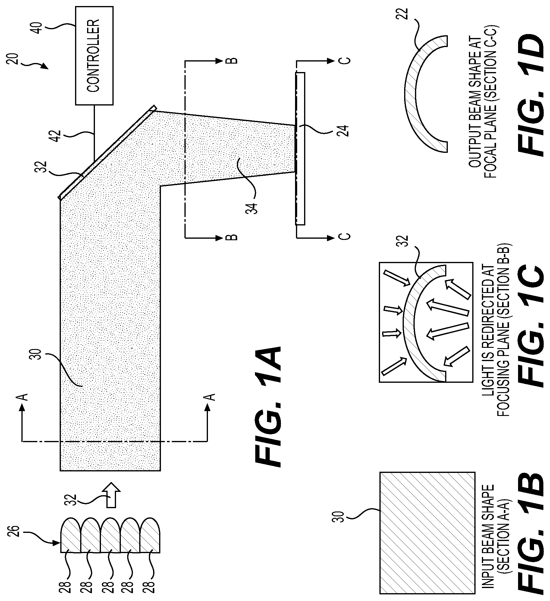
This PCT International Patent Application claims the benefit of and priority to U.S. Provisional Patent Application Ser. No. 62/771,255, filed on Nov. 26, 2018, titled “High-Power Dynamic Lens for Additive Manufacturing,” the entire disclosure of which is hereby incorporated by reference. The present disclosure relates generally to a dynamic lens for projecting different output beam shapes upon a target. Lenses are used in various applications including forming a high-power light beam into an output beam shape on a target for applications such as welding and additive manufacturing (“AM”). Such lenses must be able to withstand exposure to high-power light beams through a large number of cycles or pulses throughout the lifetime of the lens. Dynamic type lenses are capable of changing to form a light beam into different shapes. Thus far, dynamic lenses have not been suitable for high-power applications because available dynamic lenses have required electrodes or other fragile materials that are damaged by the high-power light beams passing therethrough. The present disclosure provides a dynamic lens for projecting different output beam shapes upon a target for the purpose of melting, fusing, or otherwise changing the material state. The dynamic lens includes a first light source generating a first light beam, and a lensing array including a plurality of liquid crystal cells each configured to modulate a phase of the first light beam in response to an electrical stimulation. The liquid crystal cells of the lensing array are configured to operate in conjunction to curve and focus the first light beam into a second light beam forming an output beam shape on a target. Other advantages of the present invention will be readily appreciated, as the same becomes better understood by reference to the following detailed description when considered in connection with the accompanying drawings wherein: Recurring features are marked with identical reference numerals in the figures, in which example embodiments of a dynamic lens for projecting a plurality of different output beam shapes upon a target, and a method of operating such a dynamic lens are disclosed. The system and method of the present disclosure therefore provides for an output beam shape which is dynamically adjustable, meaning its shape and points of focus can be quickly changed. The invention also provides for an output beam with substantially all of the first light beam transmitted to the target. This is an improvement over prior art “masking” type beam former which mask or direct a portion of the first light beam away from the target in order to create a desired beam shape. A dynamic lens according to the present invention allows for targets or frames that vary in size within the limits of the size of the lensing array. A dynamic lens also allows for variable power density depending on frame size. This means that frame size may increase as part density decreases. Also, unlike systems that employ adaptive masks, the build rate on AM systems using a dynamic lens is not dependent on part density (frame utilization). Numerous applications can be envisioned for a high-power dynamic lens that can form substantially all of a high-power light beam into a desired beam shape. A few such applications are plastic and composite welding, metal welding, conformal cooling for injection molds, conformal cooling for hot stamping molds, metal surface treatment (i.e., polishing, temper, local annealing), prototyping, low—medium production volume replacement process for lightweight structural components (i.e., casting; composites). Such a high-power dynamic lens may have applications in many industries including, for example, automotive, aerospace production (brackets, nozzles, pump housings, etc.), military (field repair/service), medical implants, and prototyping. Referring to the Figures, wherein like numerals indicate corresponding parts throughout the several views, a dynamic lens 20 for projecting a plurality of different output beam shapes 22 upon a target 24 is generally shown. The dynamic lens 20 includes a first light source generating a first light beam 30. The first light source 26 may include one or more laser diodes 28. Alternatively or additionally, the first light source 26 may include one or more pulsed green fiber lasers, which may output laser light having a wavelength of about 532 nm. The first light source 26 may output a high-power of at least approximately 10 kW. The first light source 26 may output a lower power of less than 10 kW, for example, when starting. The dynamic lens 20 of the present invention could be used with first light beams 30 having a wide range of power, from 100 W to greater than 100 kW. As shown in A controller 40 generates a control signal 42 corresponding to the output beam shape 22 and communicates the control signal 42 to the lensing array 32. The control signal 42 may be static and remain fixed to cause the output beam shape 22 to remain constant. Such a configuration may be used, for example, in additive manufacturing (“AM”) applications where the output beam shape 22 is used to create parts having predetermined shapes. Alternatively, the control signal 42 and the output beam shape 22 may be dynamically generated, such as in rapid prototyping additive manufacturing or in applications where the output beam shape 22 is used to weld parts which may have differing contours, distances, and/or orientation from the focusing plane 48. In an example embodiment, the lensing array 32 may include one or more liquid crystal on silicon (LCOS) devices 46, each including an array of the liquid crystal cells 36 disposed on a silicon backplate 48. In another example embodiment, and as shown on As shown on As illustrated on As illustrated in In an exemplary embodiment, each of the LCOS devices 46 may be configured to focus the second light beam 34 onto a corresponding, or dedicated region of the target 24. Alternatively, two or more of the LCOS devices 46 in the lensing array 32 are each configured to focus the second light beam 34 onto an overlapping region of the target 24. In an exemplary embodiment where the first light source 26 includes a plurality of illumination elements, such as laser diodes 28, or other bulbs or light sources, each of the illumination elements may be configured to illuminate a corresponding one of the LCOS devices 46 in the lensing array 32. In other words, there may be some correspondence between the illumination elements and the LCOS devices 46. Such a correspondence may also be one illumination source associated with a group of two or more of the LCOS devices 46 or two or more illumination sources being associated with a particular one of the LCOS devices 46. Alternatively, a single illumination source in the first light source 26 may be configured to illuminate all of the LCOS devices 46 in the lensing array 32. The illumination sources may include one or more lenses to focus the light therefrom primarily onto a corresponding one or ones of the LCOS devices 46 in the lensing array 32. In an aspect of the disclosure, and as shown in the embodiment of In some embodiments, the dynamic lens 20 may also include two or more single-point lasers 60, each independent of the first light source 26 and each configured project a third light beam 62, and together tracing the outline 64 of the output beam shape 22 on the target 24. In some embodiments, there may be a scanner 66, such as a Galvano scanner, associated with each of the single-point lasers 60. Because the lensing array 32 focuses the first light beam 30 to form the output beam shape 22 instead of masking or filtering a portion of the first light beam 30, as is done in systems of the prior art, substantially all of the first light beam 30 is transmitted to the target 24 in the form of the second light beam 34. This provides for improved efficiency and higher throughput. The dynamic lens 20 of the present disclosure may also include one or more feedback devices, such as an IR camera 70 and/or a temperature controller 72 to provide for adaptive feedback control of the power level and distribution of energy on the target 24. This adaptive feedback may to provide several advantages for a variety of applications. For example, adaptive feedback may be used in welding or additive manufacturing applications to provide dimensional control and to optimize process speed. Adaptive feedback may be particularly useful in additive manufacturing applications to compensate for non-uniformities in the shape and size of powder media and/or to control a surface finish. Adaptive feedback control may also be useful to control final material properties, for example, by controlling a heating and/or cooling rate to control grain sizes in the part. In some embodiments, the temperature controller 72 may monitor one or more temperatures of the target 24 and/or a baseplate 74 holding the target 24. For example, the temperature controller 72 may include circuitry to monitor one or more thermocouples 72 embedded within the baseplate 74. In other embodiments, the temperature controller 72 may actively control heating and/or cooling of the target 24 and/or the baseplate 74. Two or more dynamic lenses 20 may be combined serially to further resolve the output beam shapes 22 upon the target 24. As described in the flow chart of The method 100 also includes 104 providing a control signal 42 to the lensing array 32, with the control signal 42 corresponding to an output beam shape 22. The control signal 42 may take the form of an electrical or optical signal and may be static or changing over time, such as with a video signal. The control signal 42 may be communicated digitally, analog, or a combination thereof, for example, using a digital to analog (D/A) or an analog to digital (A/D) converter. The method 100 also includes 106 generating an electrical stimulation on each of a plurality of liquid crystal cells 36 in the lensing array 32, with the electrical stimulation depending upon the control signal 42 and the position of the liquid crystal cell 36 within the lensing array 32. The electrical stimulation may take the form of a DC voltage between electrodes 52 in or near each of the liquid crystal cells 36. The method 100 also includes 108 modulating a phase of the first light beam 30 by each of the plurality of liquid crystal cells 36 in the lensing array 32 in response to the electrical stimulation. This step may include any modulation of the first light beam 30 the liquid crystal cells 36, including changes to the wavefront direction and/or to a polarity of the light beam 30. It may be performed by two subsequent transmissions of the first light beam 30 through the liquid crystal cells 36, such as where the first light beam 30 passes through the liquid crystal cells 36, reflects off of a reflective surface, such as a silicon backplate 48, and where it passes through the liquid crystal cells 36 a second time. The method 100 also includes 110 curving and focusing the first light beam 30 by the lensing array 32 into a second light beam 34 to form the output beam shape 22 on the target 24. This step may include using a redistribution surface map or a phase mask, such as the example shown on In an example embodiment, the lensing array 32 may also include the liquid crystal cells 36 each being disposed upon a silicon backplate 48, and the method the method 100 may also include 112 reflecting the first light beam 30 by the silicon backplate 48. This configuration is shown in In an aspect of the disclosure, the method 110 may also include the step of 114 tracing an outline 64 of the output beam shape 22 on the target 24 by a single-point laser 60. This step map be performed using a scanner 66, such as a Galvano Scanner which may function to direct the third light beam 52 in two dimensions. The scanner 66 and/or the single-point laser 50 may be directed by the controller 40, which may include special-purpose hardware and/or software, such as a digital signal processor (DSP) and field programmable gate array (FPGA) as shown in The foregoing description of the embodiments has been provided for purposes of illustration and description. It is not intended to be exhaustive or to limit the disclosure. Individual elements or features of a particular embodiment are generally not limited to that particular embodiment, but, where applicable, are interchangeable and can be used in a selected embodiment, even if not specifically shown or described. The same may also be varied in many ways. Such variations are not to be regarded as a departure from the disclosure, and all such modifications are intended to be included within the scope of the disclosure. Many modifications and variations of the present invention are possible in light of the above teachings and may be practiced otherwise than as specifically described while within the scope of the appended claims. These antecedent recitations should be interpreted to cover any combination in which the inventive novelty exercises its utility. A dynamic lens for projecting different output beam shapes upon a target for heating, melting, or otherwise modifying the state of the target material. The dynamic lens includes a first light source of high power laser diodes generating a first light beam onto a lensing array with an LCOS device including a plurality of liquid crystal cells to curve and focus the first light beam into a second light beam forming the output beam shape on the target. A controller generates a control signal corresponding to the output beam shape. A single-point laser projects a third light beam tracing an outline of the output beam shape on the target to more clearly define the edge of the output beam shape. The single-point laser may be an IR fiber laser source scanned or traced by a scanner, such as a galvano scanner, directing the third light beam in two dimensions. 1. A dynamic lens comprising:
a first light source generating a first light beam; a lensing array including a plurality of liquid crystal cells each configured to modulate a phase of the first light beam in response to an electrical stimulation; said liquid crystal cells configured to operate in conjunction together to curve and focus said first light beam into a second light beam forming an output beam shape on a target. 2. The dynamic lens of 3. The dynamic lens of 4. The dynamic lens of 5. The dynamic lens of 6. The dynamic lens of 7. The dynamic lens of wherein each of said illumination elements is configured to illuminate a corresponding one of said LCOS devices in said lensing array. 8. The dynamic lens of 9. The dynamic lens of 10. The dynamic lens of 11. The dynamic lens of 12. A method of operating a dynamic lens comprising:
generating a first light beam upon a lensing array by a first light source; providing a control signal to the lensing array, with the control signal corresponding to an output beam shape; generating an electrical stimulation on each of a plurality of liquid crystal cells in the lensing array, with the electrical stimulation depending upon the control signal and the position of the liquid crystal cell within the lensing array; modulating a phase of the first light beam by each of the plurality of liquid crystal cells in the lensing array in response to the electrical stimulation; curving and focusing the first light beam by the lensing array into a second light beam to form the output beam shape on a target. 13. The method of operating a dynamic lens of reflecting the first light beam by the silicon backplate. 14. The method of operating a dynamic lens of tracing an outline of the output beam shape on the target by a single-point laser. 15. The method of operating a dynamic lens of 16. The method of 17. The method of 18. The dynamic lens of 19. The dynamic lens of 20. The dynamic lens of CROSS-REFERENCE TO RELATED APPLICATION
FIELD
BACKGROUND
SUMMARY
BRIEF DESCRIPTION OF THE DRAWINGS
DETAILED DESCRIPTION