TWO-STEP CAM CONTROLLED EXHAUST VALVE DEACTIVATION TO OPERATE A DIVIDED EXHAUST BOOST SYSTEM
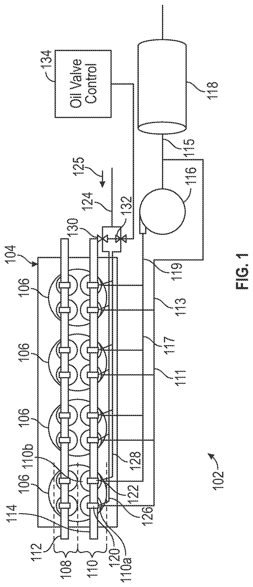
As is generally known, a divided exhaust boost system can be used to reduce internal residual pumping and improve catalyst light-off of a turbocharged spark ignition engine. However, in such a setting, the turbocharger normally fails to deliver the full boost pressure at peak engine loads due to the partial loss of exhaust gas energy to the turbine. A conventional solution for this issue involves the use of two external valves. In such a system, one blowdown valve is mounted on the route of a blowdown path connected to the turbine inlet. One scavenging valve is mounted on the route of scavenging path connected to the inlet of catalytic converter downstream of the turbine. The two valves are typically on-off valves. However, the arrangement still places constraints on exhaust gas temperature in a manner that adversely affects performance. This summary is provided to introduce a selection of concepts that are further described below in the detailed description. This summary is not intended to identify key or essential features of the claimed subject matter, nor is it intended to be used as an aid in limiting the scope of the claimed subject matter. In one aspect, embodiments disclosed herein relate to an exhaust system including a plurality of cylinders. Each cylinder includes a scavenge exhaust valve and a blowdown exhaust valve. The exhaust system also includes an arrangement that activates and deactivates the scavenge exhaust valves and the blowdown exhaust valves. Additionally, the exhaust system includes a scavenge path leading from the scavenge exhaust valves and a blowdown path leading from the blowdown exhaust valves. Furthermore, the exhaust system includes a cam shaft including a plurality of scavenge cams and a plurality of blowdown cams. During rotation of the cam shaft, the scavenge cams interact with the scavenge exhaust valves to open and close the scavenge exhaust valves when the scavenge exhaust valves are activated. Additionally, during rotation of the cam shaft, the blowdown cams interact with the blowdown exhaust valves to open and close the blowdown exhaust valves when the blowdown exhaust valves are activated, and at different times with respect to the opening and closing of the scavenge exhaust valves. In one aspect, embodiments disclosed herein relate to a method that includes providing a plurality of cylinders in an engine, each cylinder comprising a scavenge exhaust valve and a blowdown exhaust valve. The scavenge exhaust valves and the blowdown exhaust valves are activated, and a cam shaft including a plurality of scavenge cams and a plurality of blowdown cams is rotated. During rotation of the cam shaft, the scavenge cams interact with the scavenge exhaust valves to open and close the scavenge exhaust valves. Also, during rotation of the cam shaft, the blowdown cams interact with the blowdown exhaust valves to open and close the blowdown exhaust valves, and at different times with respect to the opening and closing of the scavenge exhaust valves. Other aspects and advantages of the claimed subject matter will be apparent from the following description and the appended claims. Specific embodiments of the disclosed technology will now be described in detail with reference to the accompanying figures. Like elements in the various figures are denoted by like reference numerals for consistency. In the following detailed description of embodiments of the disclosure, numerous specific details are set forth in order to provide a more thorough understanding of the disclosure. However, it will be apparent to one of ordinary skill in the art that the disclosure may be practiced without these specific details. In other instances, well-known features have not been described in detail to avoid unnecessarily complicating the description. Throughout the application, ordinal numbers (e.g., first, second, third, etc.) may be used as an adjective for an element (i.e., any noun in the application). The use of ordinal numbers is not to imply or create any particular ordering of the elements nor to limit any element to being only a single element unless expressly disclosed, such as using the terms “before”, “after”, “single”, and other such terminology. Rather, the use of ordinal numbers is to distinguish between the elements. By way of an example, a first element is distinct from a second element, and the first element may encompass more than one element and succeed (or precede) the second element in an ordering of elements. Broadly contemplated herein, in accordance with one or more embodiments, is the use of exhaust valves existing on an engine cylinder head to control the flow of exhaust gas to divided exhaust systems. This then permits an increase in the exhaust gas temperature in view of the exhaust valve design specifications involved, and offers an improvement in flow efficiency into and out of exhaust ports. The result is to expand or multiply the benefit of a divided exhaust boost on engine emission and efficiency. Also broadly contemplated herein, in accordance with one or more embodiments, is a manner of controlling the noted exhaust to effect a desired flow direction for the divided exhaust boost system requires. To this end, a two-step switchable exhaust valve deactivation arrangement can be used to open and close each of the exhaust valves on a cylinder independently. Such a deactivation system can be embodied by a cam system including cams acting on followers associated with different exhaust valves, and a manner of supplying oil to the valves in a manner to effect independent control of each exhaust valve. The disclosure now turns to working examples of a divided exhaust system and related components in accordance with one or more embodiments, as described and illustrated with respect to Additionally, to facilitate easier reference when describing In accordance with one or more embodiments, one exhaust valve 110 of each cylinder 106 is referred to as a scavenge exhaust valve 110 In accordance with one or more embodiments, mounted on exhaust cam shaft 114 are a plurality of scavenge cams 120 and blowdown cams 122. In a manner to be described more fully below, as the exhaust cam shaft 114 rotates, the scavenge cams 120 are configured to actuate an opening and closing of the scavenge exhaust valves 110 In accordance with one or more embodiments, an oil line 124 feeds into the engine 104 in the general direction indicated at 126. Line 124 then splits into two separate galleries (or lines), namely a first gallery 126 and a second gallery 128. The first gallery 126 feeds into each of the scavenge exhaust valves 110 In accordance with one or more embodiments, control unit 134 can suitably assume any of a very wide variety of possible forms for the purpose of actuating the oil valves 130, 132. For instance, oil valves 130, 132 may be configured as solenoid or piezo valves with on/off functioning as generally known, and control unit 134 can be configured to send a signal to actuate the valves 130, 132. Also, while oil valves 130, 132 are illustrated and described herein for the purpose controlling the activation and deactivation of exhaust valves 110, the exhaust valves 110 may alternatively be activated/deactivated by another, analogously acting system, such as an electric, pneumatic or piezo system. In accordance with one or more embodiments, when first oil valve 130 is closed, oil pressure in first gallery 126 is relatively low, at a first oil pressure level. In response to this lower oil pressure, a component of each scavenge exhaust valve 110 Likewise, in accordance with one or more embodiments, when second oil valve 132 is closed, oil pressure in second gallery 126 is relatively low, at a first oil pressure level. In response to this lower oil pressure, a component of each blowdown exhaust valve 110 Generally, in accordance with one or more embodiments, oil pressure at the scavenge and exhaust blowdown valves 110 Further, in accordance with one or more embodiments, oil valve control unit 134 may be configured to control the oil valves 130 and 132 relative to one another in a manner to effect a predetermined pattern or protocol of opening and closing the scavenge and blowdown exhaust valves 110 In accordance with one or more embodiments, In accordance with one or more embodiments, though two off lobes 138 are shown for scavenge cam 120 and two off lobes 142 are shown for blowdown cam 122, it should be understood that such a configuration is merely presented by way of illustrative and non-restrictive example. As an alternative, it is possible to include only one off lobe 138 for scavenge cam 120 and one off lobe 142 for blowdown cam 122. In yet another alternative implementation, it is possible to include two on lobes 136 disposed axially on either side of a single off lobe 138 for scavenge cam 120, and to include two on lobes 140 disposed axially on either side of a single off lobe 142 for blowdown cam 122. In accordance with one or more embodiments, also illustrated in In accordance with one or more embodiments, blowdown exhaust valve 110 In accordance with one or more embodiments, any of a wide variety of possible implementations may be employed for the finger followers 144 and 152. For instance, suitable mechanics of a switchable finger follower may be appreciated, e.g., from Zurface, A., Brownell, S., Genise, D., Tow, P. et al., “Design and Development of a Switching Roller Finger Follower for Discrete Variable Valve Lift in Gasoline Engine Applications,” In accordance with one or more embodiments, also illustrated schematically in In accordance with one or more embodiments, though secondary movable portion 356 is very schematically shown as displacing in a sliding manner with respect to main body 358, it should be understood that other types of independent displacement of the secondary movable portion 356 are also possible. For instance, the secondary movable portion 356 may be pivot-mounted on main body 358, and may pivot in response to engagement by cam on lobe 336 while the main body 358 remains stationary. In accordance with one or more embodiments, it should be understood that while a finger follower 344 for a scavenge exhaust valve has been described with respect to In accordance with one or more embodiments, and relative to the example shown in Initially, in accordance with one or more embodiments, a plurality of cylinders are provided in an engine, each cylinder including a scavenge exhaust valve and a blowdown exhaust valve (Step 570). This can correspond to the engine 104, cylinders 106 and scavenge exhaust valves 110 In accordance with one or more embodiments, during rotation of the cam shaft, the scavenge cams can interact with the scavenge exhaust valves to open and close the scavenge exhaust valves (Step 576). Also during rotation of the cam shaft, the blowdown cams can interact with the blowdown exhaust valves to open and close the blowdown exhaust valves, and at different times with respect to the opening and closing of the scavenge exhaust valves (Step 578). This can correspond to the opening and closing of scavenge and blowdown exhaust valves 110 Instead of using two external valves (namely the blow down valve and the scavenging valve) to control the route of exhaust gas flow, embodiments disclosed herein use the exhaust valve originally on the engine to control the exhaust gas flow for divided exhaust boost. In addition, those exhaust valves are controlled by the process of In view of the foregoing, it should be appreciated that, in accordance with one or more embodiments, advantages are gained via effectively increasing a limit of exhaust gas temperatures in comparison with the conventional arrangement noted earlier. Particularly, this is permitted via exhaust valve design specifications and also via an appreciable increase in flow efficiency via the use of exhaust ports on the engine. This enhances general benefits associated with a divided exhaust boost in relation to engine emissions and efficiency. Although only a few example embodiments have been described in detail above, those skilled in the art will readily appreciate that many modifications are possible in the example embodiments without materially departing from this invention. Accordingly, all such modifications are intended to be included within the scope of this disclosure as defined in the following claims. In the claims, means-plus-function clauses are intended to cover the structures described herein as performing the recited function and not only structural equivalents, but also equivalent structures. Thus, although a nail and a screw may not be structural equivalents in that a nail employs a cylindrical surface to secure wooden parts together, whereas a screw employs a helical surface, in the environment of fastening wooden parts, a nail and a screw may be equivalent structures. It is the express intention of the applicant not to invoke 35 U.S.C. § 112(f) for any limitations of any of the claims herein, except for those in which the claim expressly uses the words ‘means for’ together with an associated function. An exhaust system includes a plurality of cylinders, and each cylinder includes a scavenge exhaust valve and a blowdown exhaust valve. A scavenge path leads from the scavenge exhaust valves and a blowdown path leads from the blowdown exhaust valves. An arrangement activates and deactivates the scavenge exhaust valves and the blowdown exhaust valves. Further included is a cam shaft including a plurality of scavenge cams and a plurality of blowdown cams. During rotation of the cam shaft, the scavenge cams interact with the scavenge exhaust valves to open and close the scavenge exhaust valves when the scavenge exhaust valves are activated. Additionally, during rotation of the cam shaft, the blowdown cams interact with the blowdown exhaust valves to open and close the blowdown exhaust valves when the blowdown exhaust valves are activated, and at different times with respect to the opening and closing of the scavenge exhaust valves. 1. An exhaust system comprising:
a plurality of cylinders; each cylinder comprising a scavenge exhaust valve and a blowdown exhaust valve; an arrangement that activates and deactivates the scavenge exhaust valves and the blowdown exhaust valves, the arrangement comprising:
a first oil gallery that feeds oil to each of the scavenge exhaust valves; and a second oil gallery, separate from the first oil gallery, that feeds oil to each of the blowdown exhaust valves; a scavenge path leading from the scavenge exhaust valves; a blowdown path leading from the blowdown exhaust valves; and a cam shaft including a plurality of scavenge cams and a plurality of blowdown cams; wherein, during rotation of the cam shaft:
the scavenge cams interact with the scavenge exhaust valves to open and close the scavenge exhaust valves when the scavenge exhaust valves are activated; and the blowdown cams interact with the blowdown exhaust valves to open and close the blowdown exhaust valves when the blowdown exhaust valves are activated, and at different times with respect to the opening and closing of the scavenge exhaust valves. 2. The exhaust system according to a turbine; wherein the blowdown path leads from the blowdown exhaust valves to the turbine. 3. The exhaust system according to 4. The exhaust system according to a catalytic converter; wherein the scavenge path leads from the scavenge exhaust valves to the catalytic converter. 5. (canceled) 6. The exhaust system according to an oil line; a first oil valve that admits a flow of oil from the oil line to the first oil gallery; and a second oil valve that admits a flow of oil from the oil line to the second oil gallery. 7. The exhaust system according to the arrangement that activates and deactivates the scavenge exhaust valves and the blowdown exhaust valves comprises a control unit; and the control unit controls opening and closing of each of the first and second oil valves. 8. The exhaust system according to the scavenge exhaust valves are activated in response to closure of the first oil valve and a reduction in oil pressure in the first oil gallery; and the blowdown exhaust valves are activated in response to closure of the second oil valve and a reduction in oil pressure in the second oil gallery. 9. The exhaust system according to the scavenge exhaust valves are deactivated in response to opening of the first oil valve and an increase in oil pressure in the first oil gallery; and the blowdown exhaust valves are deactivated in response to opening of the second oil valve and an increase in oil pressure in the second oil gallery. 10. The exhaust system according to the scavenge exhaust valves are deactivated in response to opening of the first oil valve and an increase in oil pressure in the first oil gallery; and the blowdown exhaust valves are deactivated in response to opening of the second oil valve and an increase in oil pressure in the second oil gallery. 11. The exhaust system according to the scavenge cams each include an on lobe and one or more off lobes; and the scavenge exhaust valves each include a movable component; wherein the on lobe includes a cam profile to engage with the movable component to periodically move the movable component and open and close the scavenge exhaust valve; and wherein the one or more off lobes include no cam profile configured to effect movement of the movable component. 12. The exhaust system according to 13. The exhaust system according to the blowdown cams each include an on lobe and one or more off lobes; and the blowdown exhaust valves each include a movable component; wherein the on lobe includes a cam profile to engage with the movable component to periodically move the movable component and open and close the blowdown exhaust valve; and wherein the one or more off lobes include no cam profile configured to effect movement of the movable component. 14. The exhaust system according to 15. The exhaust system according to the scavenge cams each include an on lobe and one or more off lobes; and the scavenge exhaust valves each include a movable component; wherein the on lobes of the scavenge cams each include a cam profile, wherein the cam profiles engage with the movable components of the scavenge exhaust valves to periodically move the movable components of the scavenge exhaust valves and open and close the scavenge exhaust valves; and wherein the one or more off lobes of each of the scavenge cams include no cam profile configured to effect movement of the movable components of the scavenge exhaust valves. 16. A method comprising:
providing a plurality of cylinders in an engine, each cylinder comprising a scavenge exhaust valve and a blowdown exhaust valve; activating the scavenge exhaust valves and the blowdown exhaust valves via:
feeding oil to each of the scavenge exhaust valves via a first oil gallery; and feeding oil to each of the blowdown exhaust valves via a second oil gallery that is separate from the first oil gallery; and rotating a cam shaft including a plurality of scavenge cams and a plurality of blowdown cams; wherein, during rotation of the cam shaft: the scavenge cams interact with the scavenge exhaust valves to open and close the scavenge exhaust valves; and the blowdown cams interact with the blowdown exhaust valves to open and close the blowdown exhaust valves, and at different times with respect to the opening and closing of the scavenge exhaust valves. 17. The method according to 18. The method according to 19. The method according to the scavenge exhaust valves are activated via feeding oil to the scavenge exhaust valves at a first oil pressure level; and the scavenge exhaust valves are deactivated via feeding oil to the scavenge exhaust valves at a second oil pressure level that is greater than the first oil pressure level. 20. The method according to the blowdown exhaust valves are activated via feeding oil to the blowdown exhaust valves at a first oil pressure level; and the blowdown exhaust valves are deactivated via feeding oil to the blowdown exhaust valves at a second oil pressure level that is greater than the first oil pressure level.BACKGROUND
SUMMARY
BRIEF DESCRIPTION OF DRAWINGS
DETAILED DESCRIPTION