Exhaust manifold for an internal combustion engine produced using a flexible intermediary layer acting as the core for casting the external envelope and for compensating for distortions during use of the manifold
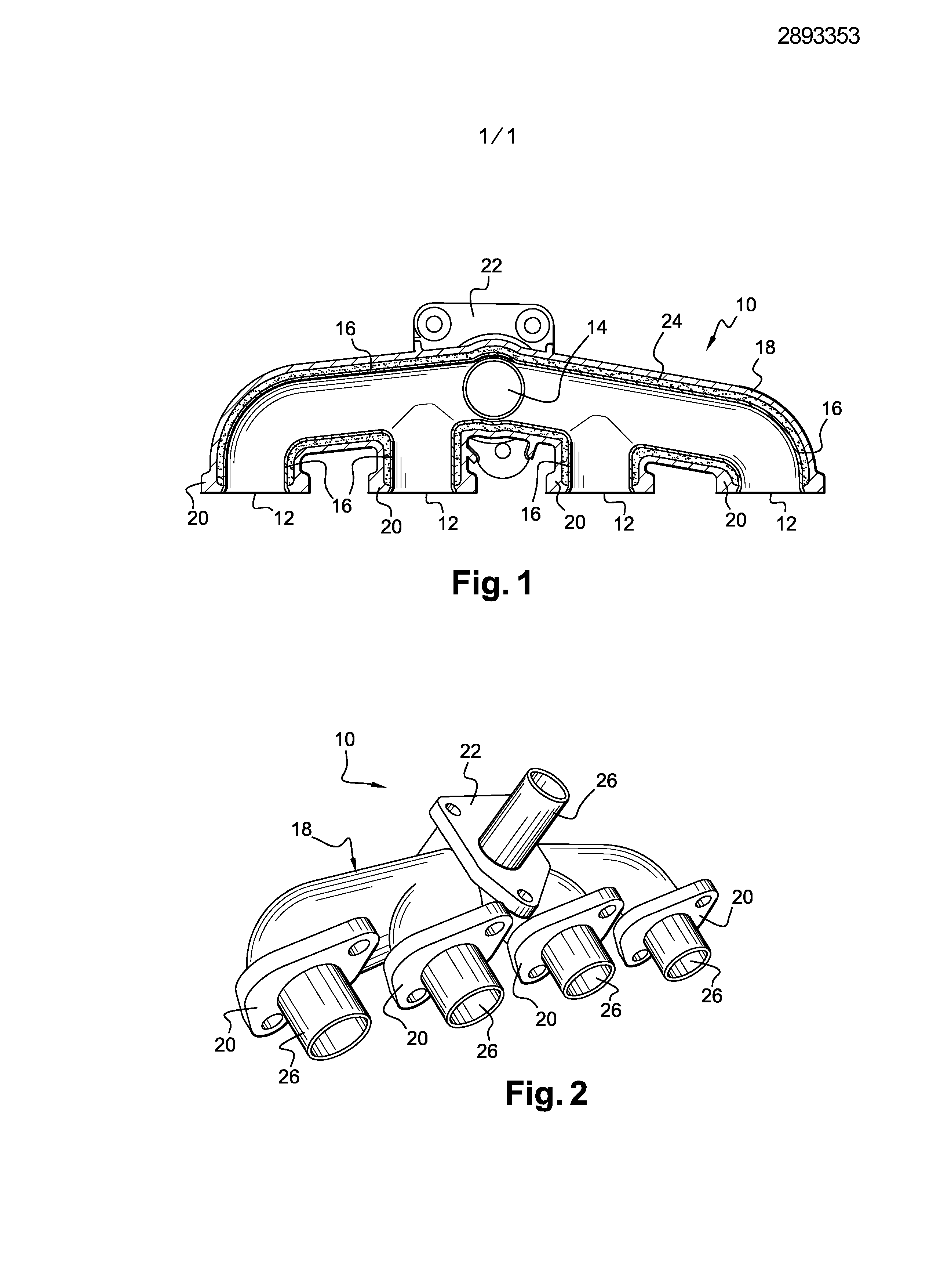
An exhaust manifold of an internal combustion engine and method of manufacturing the same. More particularly an exhaust manifold of an internal combustion engine, in particular for a motor vehicle, the exhaust manifold comprising: -at least one internal conduit which is for guiding the exhaust gases; -a rigid outer housing which is arranged round the internal exhaust duct; -an intermediate layer of thermal insulation which is interposed between the inner conduit and the outer shell; the outer shell being made by casting around the intermediate layer which forms mold core. Such a collector exhaust manifold is also called "double wall". Are known exhaust manifolds of a similar type in which the outer envelope is formed of two half-shell are joined together by welding around the inner conduit. However, the mechanical properties of such a outer shell are not adapted to the mechanical stresses and vibration inherent in use on a motor vehicle. Are known exhaust manifolds, the outer skin is moulded around the inner conduit, in particular by the document US-A- [...]. The document provide an exhaust manifold having a deformable intermediate layer which is interposed between the outer shell and the insulating intermediate layer. The deformable intermediate layer is intended to compensate the volume variations caused by the expansion of the outer shell. Furthermore, the deformable intermediate layer also has a function for core moulding during manufacture by molding the outer shell around the inner conduit. However, such a manifold is expensive and complex to perform. To solve this problem, the invention provides an exhaust manifold of the type previously described, characterized in that the intermediate layer is comprised of a flexible material to compensate for the compressions and expansions of the space between the inner conduit and the outer shell due to the difference between the expansion of the outer casing and the expansion of the inner conduit. In other features of the invention: -the intermediate layer is made of a fibrous material suitable for withstanding the melting temperature of the material forming the outer jacket; -the outer shell is made of cast iron; -the intermediate layer is made of rock wool. The invention also relates to a method for manufacturing such a manifold, characterized in that it comprises a first step of wrap of the inner conduit with the intermediate layer, and a second step of positioning in a mould the inner conduit and wrapped, and a third step of molding in which a molten material is cast into the mold to form the outer shell, the intermediate layer forming mold core. Other features and advantages of the invention shall become apparent from the detailed description which will follow for understanding of offload which is to the accompanying drawings of which: -figure 1 is a bottom view in longitudinal section, which represents an exhaust manifold designed according to the teachings of the invention; -figure 2 is a perspective view that represents the manifold of Figure 1 at an intermediate stage of the method of making. Thereafter, identical elements, like or the like will be indicated by the same reference numbers. The in Figure 1 an exhaust manifold 10 which is intended to be arranged on a cylinder head for an internal combustion engine (not shown), in particular for a motor vehicle, to guide the exhaust gas to an exhaust downstream pipe (not shown). In a known manner, the manifold 10 comprises four upstream ports 12 which are to be connected to exhaust ports of the cylinder head, and a single downstream port 14 which is intended to be connected to the exhaust downstream pipe. Each upstream opening 12 is connected to the downstream port 14 by an inner conduit 16, the wall of which consists of a material having a low thermal inertia, for example the internal passages are made of thin-walled metal sheet. The exhaust manifold 10 having a plurality of upstream ports 12 and a single downstream port 14, the internal conduit 16 herein includes more branches, which are each connected to an upstream port 12 or 14 downstream. The inner conduit 16 is surrounded by a rigid outer shell 18 which is intended to ensure sufficient stiffness and strength to withstand the vibration and stresses transmitted to the exhaust manifold 10 during operation of the engine and during the motor vehicle travel. The outer shell 18 leaves the upstream ports 12 and 14 downstream released. The rigidity of the outer shell 18 is imparted by the mechanical characteristics of its constituent material, and on the other hand by its geometry. Therefore, the material used is a metal, e.g. cast iron. The outer shell 18 is thick relative to the thinness of the inner conduits 16 so as to increase the rigidity and mechanical strength of the exhaust manifold 10. The outer shell 18 are integrally formed in one piece in particular to support more easily the vibratory stress inherent for use in a motor vehicle. The method of making the outer shell 18 will be detailed subsequently. The outer shell 18 also has clamps 20 that project radially around the upstream ports 12 and a fastening flange 22 which surrounds the downstream port 14. The clamps 20 which surround the upstream ports 12 can be attached to the cylinder head of the engine, and that the fastening flange 22 which surrounds the downstream port 14 is adapted to be secured to a mounting flange associated of the exhaust line. The clamps 20,22 include examples of the fixing holes which are intended to receive fastening screws. The clamps 20,22 are formed integrally with the outer shell 18. In a known manner, an intermediate layer 24 of thermal insulation is interposed between the inner conduit 16 and the outer shell 18. The intermediate layer 24 prevents the heat of the exhaust gas is transmitted to the outer shell 18 via the inner conduit 16. Therefore, thermal stresses experienced by the outer shell 18 are reduced. Furthermore, the hot exhaust gases lose little heat through the intermediate layer 24 so that their temperature is kept high. This feature is particularly advantageous when the downstream conduit is equipped with a catalyst, or of a device for treating the equivalent gas, to be heated to a temperature of ignition by the hot exhaust gases to become active. The only direct contact surfaces between the outer shell 18 and the inner duct 16 are arranged around the upstream ports 12 and 14 downstream to seal the exhaust manifold 10 at the fastening flanges 20,22. Therefore, the inner cylindrical face of each bracket 20,22 is tightly fitted around the outer cylindrical face of the inner conduit 16 which delimits the upstream 12 or downstream port 14 associated. According to the teachings of the invention, the electrically insulating intermediate layer 24 is made of a material which, in addition to being a good heat insulator, is sufficiently flexible to absorb the compressions and expansions the volume between the inner conduit 16 and the outer shell 18. The volume change is due to the difference between the expansion of the outer shell 18 and expansion of the inner conduits 16, i.e. the outer shell 18 and the inner duct 16 have different coefficients of expansion, and they are further capable of being simultaneously subjected to two different temperatures. For example, to a normal temperature of about 25 °C, the internal conduit 16 has an initial shape. In use of the exhaust manifold 10 in an internal combustion engine, the internal conduit 16 can be deformed from its initial shape of the fact that it is subjected to strong temperature rises by heat exchange with the hot exhaust gases, for example to 350 °C. The inner conduit 16 is then expanded and deformed under the effect of this high temperature rise. Furthermore, the outer shell 18 is also capable of being heated by heat which radiates into the engine compartment of the vehicle. However, the outer shell 18 deforms a different manner to that of inner conduit 16 in particular because the outer shell 18 has a structure, a geometry that are different from those of the inner conduit 16. Furthermore, the temperature at which the outer shell 18 is heated by radiation, can be less than the temperature at which the inner conduit 16 is heated by the hot exhaust gases. This difference in deformation produces a variation in the volume of the space filled by the intermediate layer 24 between the inner conduit 16 and the outer shell 18, and thus causes mechanical stresses on the intermediate layer of insulation 24. The intermediate layer 24 is flexible, it is able to absorb stresses to be compressed or expanded. Therefore, the same intermediate layer 24 of the exhaust manifold 10, made of a single material, has both a thermal insulating function and a compensation function of mechanical stress. The material of the intermediate layer 24 is, for example, a fibrous material which has no binder such as rock wool. Disclosed is subsequently a method for producing such a manifold 10. In a first step of wrap, the inner conduit 16 is wrapped or wrapped in the intermediate layer 24 so that only the external cylindrical walls of the inner conduit 16 surrounding the upstream ports downstream 12 and 14 to be in contact with the outer shell 18 remain uncovered. Furthermore, in a second step of positioning, the internal conduit 16 wrapped and is arranged in a mold (not shown) the footprint corresponds to the outer shape of the outer shell 18. The mold is designed, for example, of two parts that are brought together around the inner conduit 16. The inner conduit 16 is positioned so that a free space remains between the intermediate layer 24 and the walls forming the mold cavity. Finally, in a third molding step, material for forming the outer shell 18, which will be referred to subsequently cast iron for example, but not limited to, is poured in a liquid state, at a temperature greater than or equal to its melting temperature, within the mold. The molten cast iron fills the space remaining between the intermediate layer 24 and the walls of the mold. The intermediate layer 24 thus forms a mold core about which the outer shell 18 is molded. To this end, the material constituting the intermediate layer 24 is required to resist the heat generated by the molten iron. For example, the intermediate layer 24 is made of rock wool. An indication becomes solid and further cooled, the outer shell 18 is a shrinkage phenomenon while the inner conduit 16 is not deformed. The outer shell 18 being in direct contact with the inner conduit 16 at the upstream and downstream ports 12 14, the retraction of which causes the tightening of the outer shell 18 around the inner conduit 16 at the fastening flanges 20,22. This tightening is able to impart at exhaust manifold 10 sealing previously depicted at clamps 20,22. Furthermore, shrinkage causes a compressive stress on the intermediate layer 24. The intermediate layer 24 is flexible, it compensates or absorbs removal of the outer shell 18 by compressing. Alternatively the method according to the invention shown in Figure 2, to facilitate positioning of the inner conduit 16 within the mold in the second step of positioning, the internal conduit 16 is longer than necessary, i.e. that it comprises positioning sections 26 that extend the inner conduit 16 beyond the downstream upstream ports 12 and 14. After the moulding step, positioning these sections 26 project outwardly relative to the outer shell 18. They are therefore to be pruned after the molding of the outer shell 18. Positioning The stubs 26 protrude from the mold. They thus grip and hold the internal passages 16 in the desired position the mold during the steps of positioning and molding. Such exhaust manifold 10 made according to the invention accomplishes by molding the outer shell 18 around the inner conduit 16 without having to remove the core required to mold. The moulding core is formed by the intermediate layer 24 which has a function of insulating and for compensating deformation of the inner conduit 16 and 18 of the outer shell during the entire use of the exhaust manifold 10. The resultant a method of making less expensive which does not require the use of a temporary material, such as sand, to perform the mold core. The manufacturing process is made faster because it includes no operation for removing the mold core. Furthermore, an outer shell 18 made in a single piece by molding results in more satisfactory mechanical behavior that an outer casing made by welding two half-shell. The invention also provides a manifold simple and rapid to perform and inexpensive. During the process of embodiment, the intermediate layer 24 has a first function mold core. Then the same intermediate layer 24, there is a second heat insulation function and a third compensation function of the mechanical stresses. A single material is use in carrying out these three functions. The invention relates to an exhaust manifold (10) of an internal combustion engine, in particular devéhicule automobile, the exhaust manifold (10) comprising at least an internal conduit (16) of exhaust which is intended to guide exhaust fumes, an external rigid envelope (18) which estagencée around the internal conduit of exhaust (16), and a transition course (24) of insulation thermiquequi is interposed between the internal conduit (16) and the external envelope (18), the external envelope (18) etantrealized by moulding around the transition course (24) which form core of moulding, characterized in this quela layer intermediary (24) consists of a flexible material so as to compensate for compressions etexpansions of the space ranging between the internal conduit (16) and the external envelope (18) which are due to ladifférence of dilation of the external envelope (18) compared to the internal conduit (16). The invention relates to also a method for realization of such an exhaust manifold (10). 1. An exhaust manifold (10) of an internal combustion engine, in particular for a motor vehicle, the exhaust manifold (10) comprising: -at least one inner conduit (16) exhaust for guiding the exhaust gases; -a rigid outer housing (18) which is arranged round the internal exhaust duct (16); -an intermediate layer (24) of thermal insulation which is interposed between the inner conduit (16) and the outer shell (18); the outer shell (18) being made by casting around the intermediate layer (24) which forms mold core, characterized in that the intermediate layer (24) is comprised of a flexible material to compensate for the compressions and expansions of the space between the inner conduit (16) and the outer shell (18) which are due to the difference between the expansion of the outer shell (18) and the expansion of the inner conduit (16). 2. An exhaust manifold (10) according to claim 1, characterized in that the intermediate layer (24) is made of a fibrous material suitable for withstanding the melting temperature of the material forming the outer jacket (18). 3. An exhaust manifold (10) according to the preceding claim, characterized in that the outer covering (18) is made of cast iron. 4. An exhaust manifold (10) according to any one of the preceding claims, characterized in that the intermediate layer (24) is made of rock wool. 5. A method of making an exhaust manifold (10) according to any one of the preceding claims, characterized in that it comprises a first step of wrap of the inner conduit (16) with the intermediate layer (24), and a second step of positioning in a mold of the inner conduit (16) and wrapped, and a third step of molding in which a molten material is cast into the mold to form the outer shell (18), the intermediate layer (24) forming mold core. "Double-walled exhaust manifold comprising an intermediate layer flexible thermal insulation molding core"