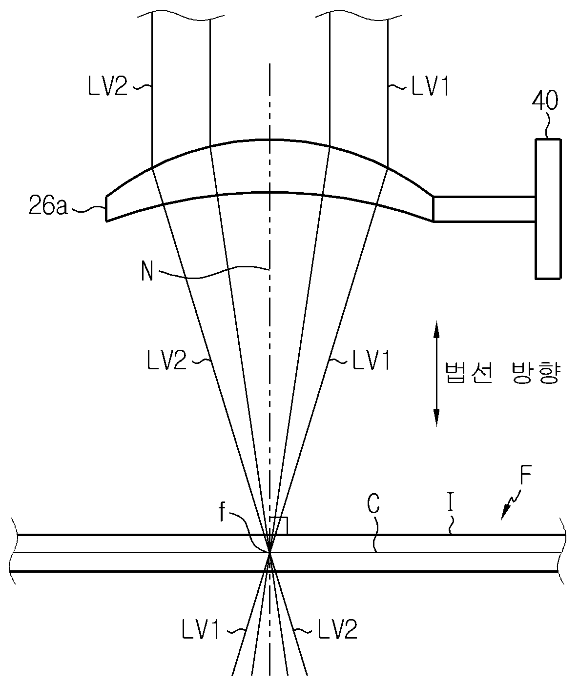
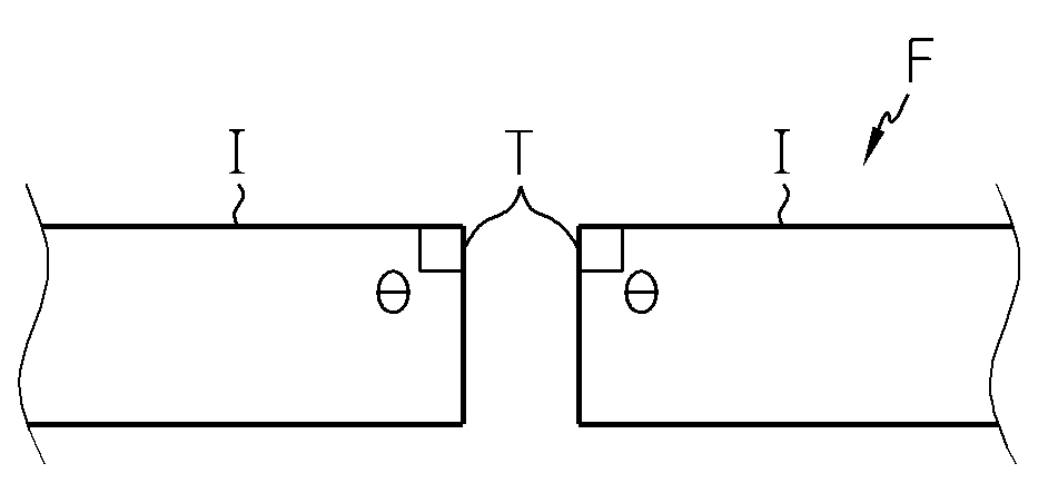
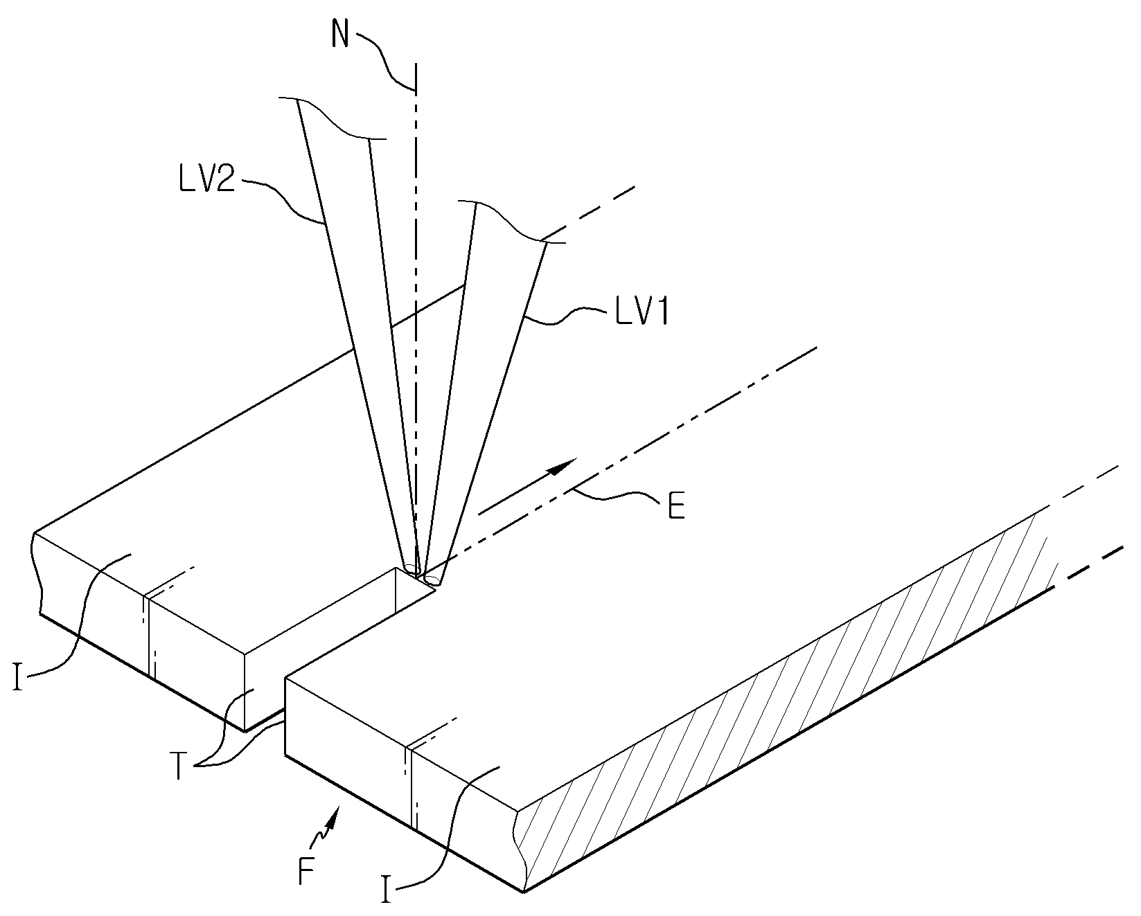
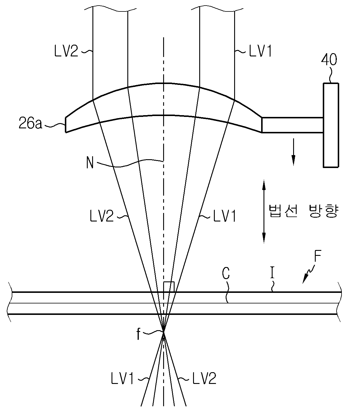
LASER CUTTING DEVICE
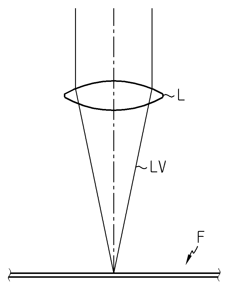
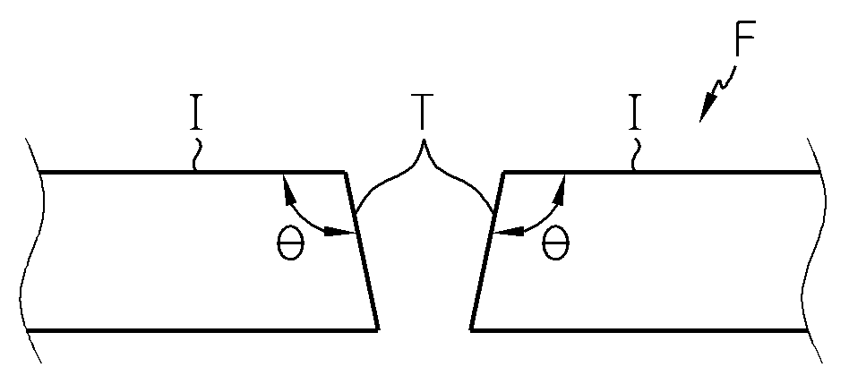
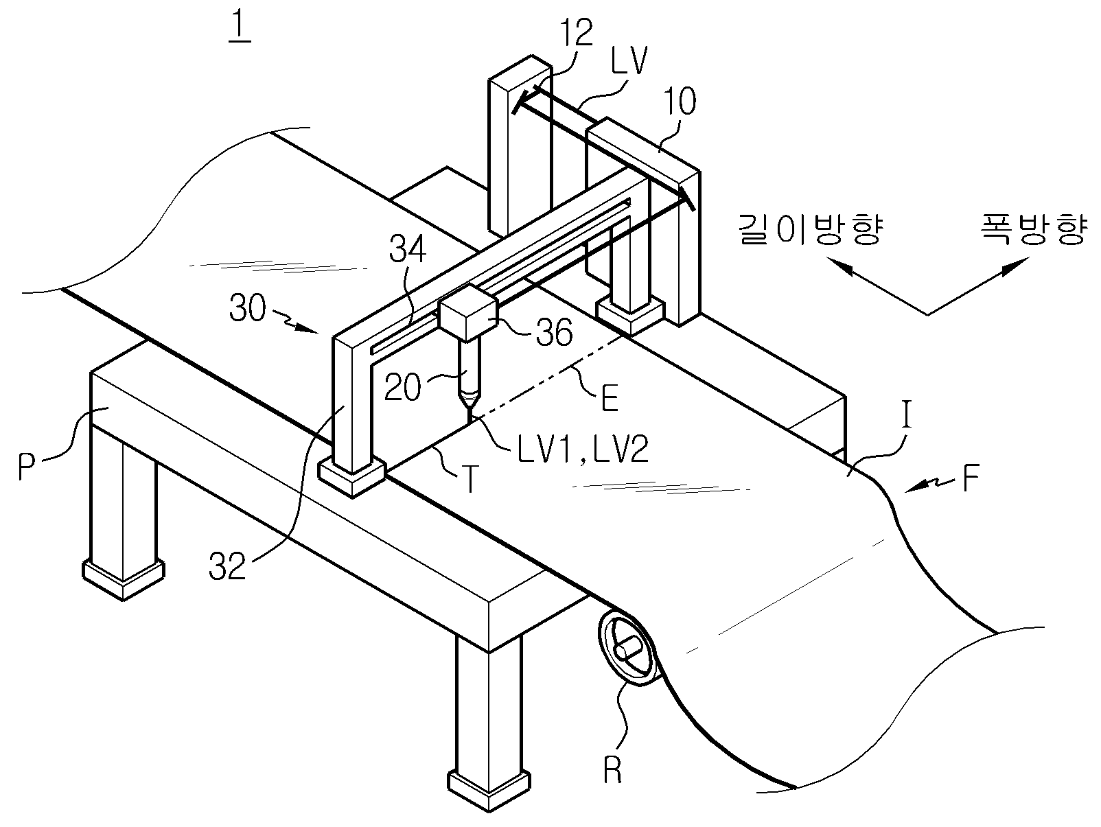
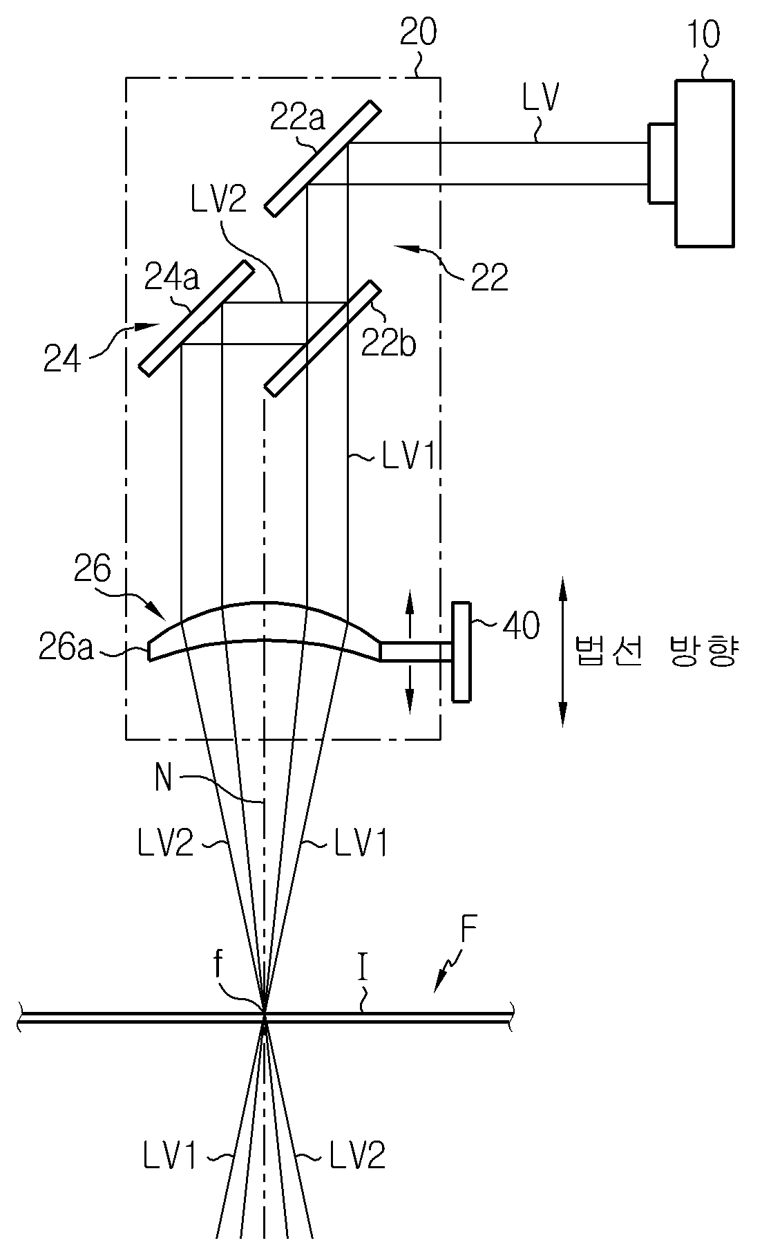
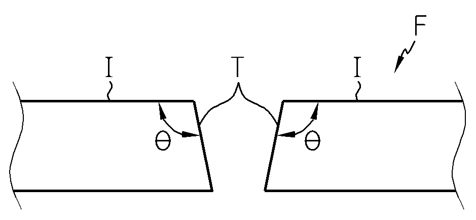
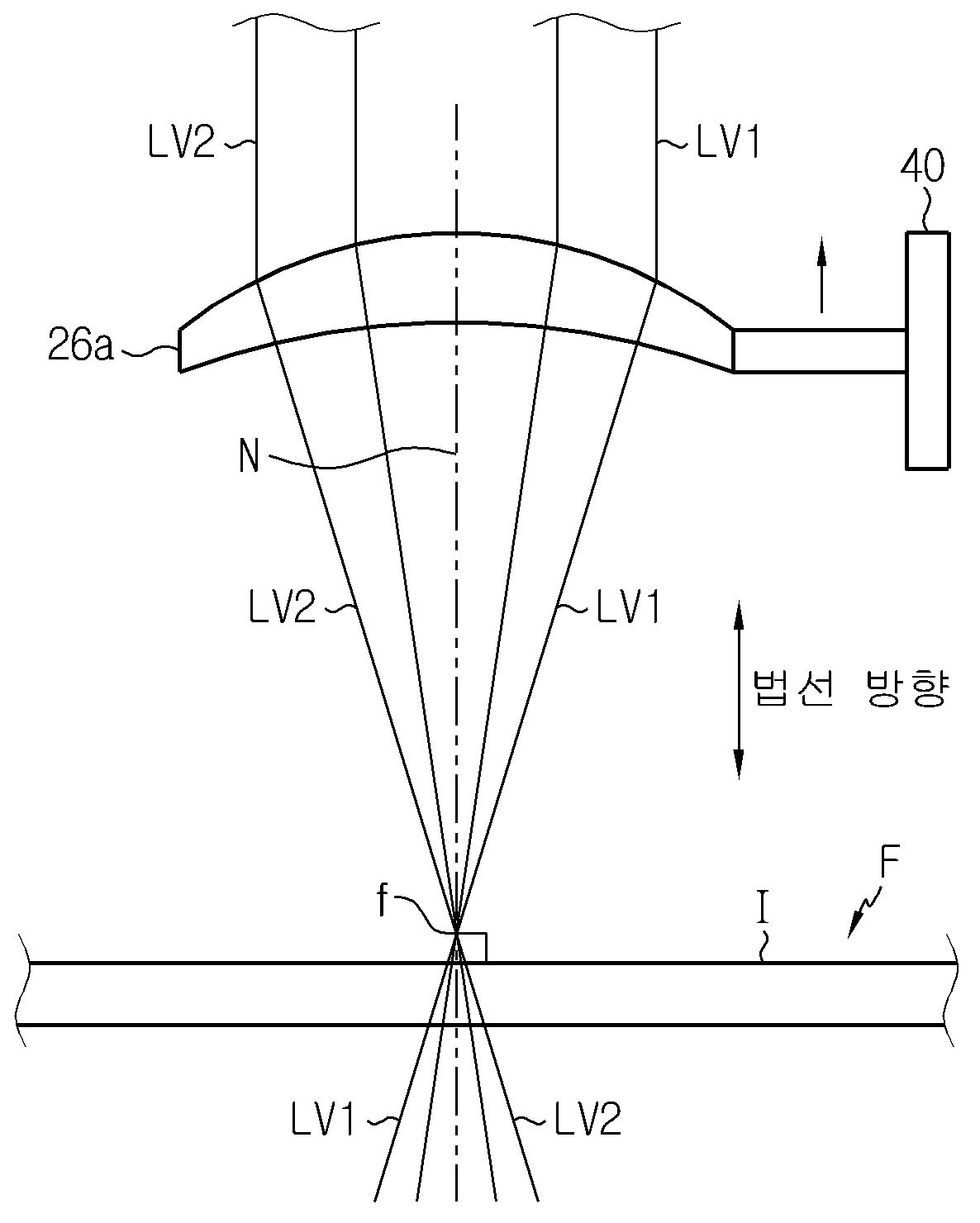
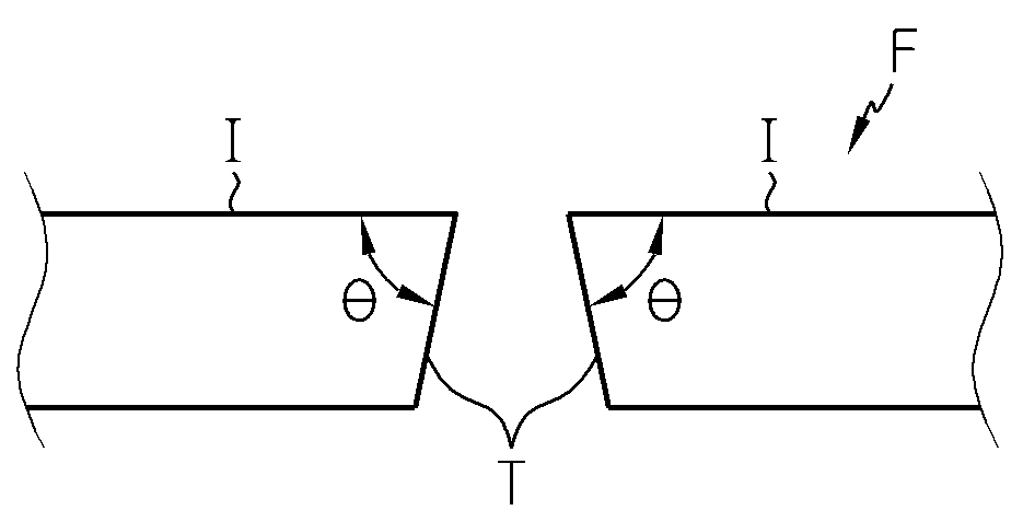
The invention relates to a laser cutting apparatus for laser-cutting object are disclosed. Object etc. often used for cutting apparatus for cutting. One of the laser cutting apparatus has a laser beam for laser cutting object such cutting device capable of use as a result of excellent physical properties etc. gradually increased. Generally laser cutting device, as shown in fig. 1, a condenser lens (L) cutting using laser beam (LV) by irradiating a light object (F), (F) object for laser cutting substrate. As shown in fig. 1, is collected by a condenser lens (L) laser beam (LV) has predetermined angles of convergence (or divergence). Thus, as shown in also 2, object to be cut by a laser beam (LV) (F) (T) and the laser beam (LV) formed by cutting (I) formed by the irradiation surface is irradiated with a cutting angle (θ) irregular aspect is equal to 72. The temperature detector, the cutting angle (θ) (F) object, object (F) handling and processing method, object (F) according to product manufactured using case must be conditioned optionally when flow tides. The temperature detector, a cutting angle (θ) is object (F) optionally adjustable laser cutting device response priority, object (F) handling and processing and, object (F) to maintain the quality of products manufactured using an electromagnetic wave exists along. The present invention relates, to resolve the problems described above texts, arranged at the end cutting edge angle of object to tire with improved laser cutting device provided the pin is. A preferred embodiment of the present invention to solve the above-described for cutting apparatus comprises a laser, laser-cutting object in laser cutting apparatus, laser beam oscillates in a laser oscillator; first and second laser beam with a laser beam by splitting a laser beam 1 division 2 division, 1 2 so that the first laser beam with a laser beam to a predetermined focus are intersected at first divided into predetermined object onto the irradiation surface condensing unit having cutting head; and irradiation surface to focus the varied spacing between cutting head, a condensing unit and object to at least one of irradiation surface along a direction normal to the feeding, object to meet the demand and cutting edge angle formed by the laser irradiation surface formed cut cutting angle regulator regulating; without using a tool. Preferably, the converter, either laser beam portion on the other of the first laser beam with a laser beam reflecting light and laser beam into first portion with mirror chromium has introduced laser beam 1 division 2. Preferably, the condensing unit, the first laser beam so that the laser beam is first divided 1 2 division are intersected at a convex lens having, along the direction of the normal surface of the irradiation surface a cutting angle regulator enabling transfer of pair of substrates. Preferably, a cutting angle regulator, such that the surface of the space of the thickness of the object to the center focus, cutting edge angle vertical adjustment of the other. Preferably, a cutting angle regulator, so as to be located away from the surface of the convex lens focus than the center thickness of object space of the, adjusting cutting edge angle at an acute angle to each other. Preferably, a cutting angle regulator, the thickness of the object surface of the convex lens and positioned close to the center focus than generated, cutting edge angle obtuse angle control each other. Preferably, cutting head is, first laser beam with a laser beam incident photon beam to symmetrically convex lens 1 2 1 first divided divided with a laser beam at least one split laser beam first introduced laser beam 2 first divided optical path changed with each other further Image into an electrical signal. Preferably, the optical path changing unit, divided laser beams with a laser beam in which the mutually corresponding first 1 division 2 first laser beam one split optical path has at least one changeable each reflecting mirror. Preferably, the second cutting head with a laser beam to reflect off a first laser beam irradiation surface symmetrically divided 1 divided 2 set on parallel lines so that the virtual cut head driver further comprises. To solve the above-described laser according to one aspect of the present invention for the cutting apparatus comprises a, laser-cutting object in laser cutting apparatus, laser beam oscillates in a laser oscillator; and a large number of split laser beam into a laser beam split, a large number of split laser beams are intersected at a predetermined focus so that the predetermined object to the irradiation surface onto the condensing unit having cutting head; and irradiation surface to focus the varied spacing between cutting head, a condensing unit and object to at least one of irradiation surface along a direction normal to the feeding, object to meet the demand and cutting edge angle formed by the laser irradiation surface formed cut cutting angle regulator regulating; without using a tool. Another aspect of the invention to solve the above-described one the sheep it buys[...] cutting apparatus comprises a laser, laser-cutting object in laser cutting apparatus, so that the multiple laser beams to a predetermined object are intersected at a predetermined intersection onto the irradiation surface at least one cutting head; and irradiation surface intersections to the varied spacing between cutting head, irradiation surface along a direction normal to the feeding at least one object, object to meet the demand and cutting edge angle formed by the laser irradiation surface formed cut cutting angle regulator regulating; without using a tool. The cutting apparatus comprises a laser according to the invention the following effect. First, the focus object to cross multiple laser beams are filled with a cutting edge angle of object by changing the intervals between the control and can maintain its required angle, laser cutting and facilitate handling and processing of the object, using laser cutting quality of a product that includes object can be to maintain a certain temperature. Second, a convex lens so that the laser beams are intersected at focus transfer control and can maintain the cutting edge angle of object by simple operation, improving the structure of the optical system of control and can maintain its cutting edge angle of object to cut to head it would cost increases can be minimize. Figure 1 shows a conventional laser cutting device to account for surface. Figure 2 shows a conventional laser cutting cut by cut object representing the status object cross-section. Figure 3 shows a schematic configuration of semiconductor laser according to a preferred embodiment are also visually representing a surface. Figure 4 shows a schematic configuration of visually representing a cutting head and cutting angle regulator also 3 also shown in surface. 5a and 5b is also shown in a cutting angle not actuated also 4 also cutting head and cutting edge angle of object vertically modulating to explain the drawing. Also in Figure 6 shows a also 5a, object to a predetermined angle along a line cutting object to a predetermined cutting angle continuously indicating an aspect cutting surface. 7a and 7b is also shown in a cutting angle not actuated also 4 also cutting head and cutting edge angle of object of modulating an obtuse angle to explain the drawing. 8a and 8b is also shown in a cutting angle not actuated also 4 also cutting head and cutting edge angle of object modulating at an acute angle to explain the drawing. The range in the description and claims the terms or word sense and in subsequent analysis or a pre-conventional defining the WD, we have found that the best method to illustrate its own invention broadly define the concept of terms most appropriate to meet the technical idea of the present invention can be predicated principle semantics and concept must be interpreted as follows. Thus, embodiments described herein coping of the present invention most preferred embodiment configuration shown only a technical idea of the present invention is both inner and replace, the present application point may replace their various variants are equal with accomplishing understanding can be negative. Each element or component thereof has a size a storing part stores descriptive convenience in drawing and clarity exaggerated or omitted for or determine the is also shown. The, each size of the components that reflect the actual size entirely are not correct. Known function or configuration description is specifically related to the subject matter of the present invention can be decided to be unnecessarily haze when, such described dispensed to other. Figure 3 shows a schematic configuration of a laser cutting device are also in a preferred embodiment visually representing a surface are disclosed. The reference also 3, a preferred embodiment of the present invention a laser cutting device (1) is, generates laser beam (LV) oscillating laser oscillator (10) on, cutting object by irradiating a laser beam (LV1) (LV2) (F), object (F) laser cutting cutting head (20) on, object to a predetermined cut line (E) (F) cutting along the cutting head (20) and a transfer head driver (30) having a predetermined wavelength. Laser cutting device (1) (F) using the kind of cleavable object is not limited particularly. For example, object (F) is, display polarizing panel be a polarizing film comprises a fabric. This object (F) is, as shown in also 3, feed roller (R) object (F) cut by a longitudinal direction of an undistributed, cutting head (20) is attached to the main frame (P) can be disposed on. First, laser oscillator (10) is, object (F) laser-cutting device for supplying a laser beam (LV) are disclosed. Laser oscillator (10) is, as shown in fig. 3, installed at one side of the main frame (P) which, generates a laser beam (LV) oscillating substrate. The laser oscillator (10) (LV) in the laser beam efficiently, laser oscillator (10) on the cutting head (20) arranged between the at least one reflective mirror (12) are modified so by a thin cutting head (20) the driven gear. Also, laser oscillator (10) on the cutting head (20) between a parallel laser beam collimator lens for shaping light (LV) installing or preferably, limited to are not correct. Next, cutting head (20) is, laser oscillator (10) then transmits laser beam cutting device object (F) (LV1) (LV2) there are disclosed. Cutting head (20) is, as shown in fig. 3, the after alcoholic beverage it will do head driver (30) for slider (36) coupled to. The cutting head (20) is, slider (36) along the lateral direction of the object (F) (is less than the, 'width direction' soap without) and into a laser oscillator (10) then transmits laser beam irradiation surface of (I) cutting (LV1) (LV2) object (F) set on a method for cutting along (E) by irradiating, object (F) along a predetermined cutting line (E) laser cutting the substrate. (I) cutting head RM irradiation surface (20) facing to the light exit surface cutting head (20) emitted laser beam (LV1) (LV2) in one aspect of it is irradiated with object (F), a method for cutting the object to a predetermined severed (E) (F) to (I) irradiation surface virtual line set on said substrate. For facilitating descriptions to is less than the, object to a predetermined length (F) to (E) (F) along the lateral direction of the object to cut line is established as an example to explain the present invention for example less than 1000. Next, head driver (30) is, cutting head (20) is a method for cutting (E) (LV2) (LV1) irradiating a laser beam along the cutting head (20) for conveying device are disclosed. Head driver (30) is, as shown in fig. 3, main frame (P) main frame so as to cross the road width direction (F) disposed object (P) which is mounted on the cross frame (32) and, cross frame (32) in the width direction formed along one side of the slit (34) and, slit (34) movably mounted in the widthwise direction of the slider (36) on, slit (34) mounted on a slider (36) a drive motor (not shown) provides driving force for the transfer line width without using a tool. Such head driver (30) is, slider (36) and slider (36) coupled to the cutting head (20) a method for cutting a (E) parallel with the lateral direction so as reciprocating driving each other. Then, cutting head (20) includes a laser oscillator (10) propagating from the laser beam along a predetermined cutting line (LV1) (LV2) (E) can be irradiated. Figure 4 shows a schematic configuration of a cutting angle regulator and also 3 also shown in cutting head visually representing a surface are disclosed. Generally laser cutting device, to be irradiated with laser beam irradiation surface and, object to cut cutting angle formed by the laser optical system having the laser cutting device formed the demand depending on the structure of laser cutting device every field[...] show differences in substrate. The ends, cutting angle such object, object handling and processing method, using an object type of a product that includes a predefined angular according to the adjusted to flow tides in order. To this end, cutting head (20) cutting a cutting angle (θ) object (F) operation of controllable optical system having, laser cutting device (1) is then cutting head with improved structure (20) for operating a cutting angle regulator of optical system (40) further comprises. First, cutting head (20) is, as shown in fig. 4, laser oscillator (10) first laser beam oscillated from the first laser beam (LV1) (LV) 1 division 2 (LV2) division of the division unit introduced laser beam (22) on, the first laser beam is first introduced laser beam (LV1) 1 2 division (LV2) condensing unit (26) symmetrically incident photon beam to division unit (22) through the second path of the first laser beam (LV1) 1 division 2 (LV2) introduced laser beam changing optical path changing unit (24) on, optical path changing unit (24) and a second laser beam through the laser beam (LV1) 1 division 2 (LV2) are intersected at a predetermined focus (f) dividing the object (F) (I) so that the predetermined irradiation surface onto the condensing unit (26) having a predetermined wavelength. Division unit (22) is, as shown in fig. 4, laser oscillator (10) (LV) laser beam oscillated from a semi-transmissive mirror (22b) toward a reflective mirror (22a) on, reflecting mirrors (22a) (LV) laser beam propagating from the light and reflect the remaining part of the light from the laser 1 (LV) corresponding to a first laser beam into a first laser beam divided (LV1) 2 (LV2) divided chromium mirror (22b) having a predetermined wavelength. Reflecting mirrors (22a) is, as shown in fig. 4, cutting head (20) into the incident laser beam (LV) which is mounted in such, a semi-transmissive mirror laser beam (LV) (22b) towards the semi-transmissive mirror (22b) to be incident on its substrate. The reflection mirror (22a) is, as shown in fig. 4, a laser beam irradiation surface (LV) (I) a direction normal (is less than the, 'the direction of the normal' soap without) is integrally formed with or preferably a voltage, limited to are not correct. Wherein, the means by which the direction of the normal, an arbitrary point on the vertical irradiation surface (I) passed vertically (N) extension directions of said substrate. Is less than the reflecting mirrors (22a) is a direction in which the reflected laser beam (LV) when for example a normal example to explain less than 1000. Semi-transmissive mirror (22b) is, as shown in fig. 4, reflecting mirrors (22a) (LV) incident laser beam reflected by the mirror surface to 45° force is removed. The semi-transmissive mirror (22b) is, mirror surface reflecting incident into the laser beam (LV) (LV) laser beam is movable to the other half transmits the same amount each other (LV1) (LV2) laser beam having a first laser beam divided 1 can be divided into 2. Also, as shown in fig. 4, mirror surface 1 (LV1) (LV) first introduced laser beam passing through the laser beam to a direction normal to such as progressing, mirror thus the vertical direction of the direction of the normal is first introduced laser beam 2 (LV2) the processing advances. Optical path changing unit (24) is, as shown in also 4, the first laser beam is first introduced laser beam (LV1) 1 2 division (LV2) the after alcoholic beverage it will do condensing unit (26) of convex lens (26a) are opposing each other incident photon beam to semi-transmissive mirror (22b) through 1 (LV1) 2 (LV2) first introduced laser beam first introduced laser beam path of at least one of the simultaneous pair of substrates. For example, optical path changing unit (24) is, the direction of the normal vertical direction 2 (LV2) first introduced laser beam incident laser beam (LV2) 45° so as a first mirror surface to a direction normal to single mirror 2 division (24a) can be a. Only, which are not limited to the, optical path changing unit (24) has a first (LV1) 1 2 (LV2) divided laser beam is introduced laser beam condensing unit (26) of convex lens (26a) 1 2 (LV1) first introduced laser beam first incident photon beam to symmetrically divided laser beam (LV2) during each single either mutually corresponding at least one reflective mirror can be. Convex lens (26a) is, as shown in fig. 4, has a predetermined focal length, lens axis parallel with the direction of the normal 1 while an upper laser beam (LV2) 2 (LV1) first introduced laser beam first incident photon beam to lens symmetrically about an axis dividing force is removed. Convex lens (26a) is, as shown in fig. 4, to reduce the aberration meniscus (Meniscus) preferably consists of convex lens. Only, and are not limited to, convex lens (26a) is, made of double convex lens or plain convex lens may be filled. Also, convex lens (26a) does not specifically defined installation of number, at least one convex lens (26a) can be provided. This convex lens (26a) is, as shown in also 4, convex lens (26a) first laser beam incident on the first convex lens (LV2) 2 1 division (LV1) introduced laser beam (26a) so that the focus of (f) to (I) of the object (F) are intersected at irradiation surface by irradiating the object (F) laser cutting substrate. The temperature detector, the first laser beam (LV1) (LV2) first introduced laser beam 1 division 2, as shown in also 4, focus (f) used to focus (f) and progressively converging passage, focus (f) (f) is applied which pass through the focus from gradual is blown into the substrate. The, 1 (LV1) first introduced laser beam irradiation surface of the first laser beam (LV2) object (I) 2 division (F) applied to an irradiation surface and a convex lens (I) object of aspects (F) (26a) (f) the focus of depending in a gap between the to be coated. This method is a cutting angle (θ) using the same object (F), a cutting angle regulator the after alcoholic beverage it will do (40) produced in a hole of a menu to nut. Next, a cutting angle regulator (40) cutting a cutting angle (θ) object (F) for regulating the condensing unit (26) for conveying device are disclosed. A cutting angle regulator (40) is, as shown in fig. 4, a convex lens (26a) which is mounted in such comes into engagement with a, convex lens (26a) to a direction normal to a reciprocating enabling transfer of pair of substrates. Such cutting regulator, manual stage (Manual stage) preferably consists of. Only, and are not limited to, cutting angle regulator (40) has a convex lens (26a) can be composed a reciprocating driving to a direction normal to a variety of devices. On the other hand, a cutting angle regulator (40) has a convex lens (26a) disclosed that but a normal direction, the pieces are not correct. I.e., a cutting angle regulator (40) is, convex lens (26a) (f) (I) (F) and object of focus of irradiation surface to adjust the spacing between the cutting head (20), object (F), convex lens (26a) configured to transfer to a direction normal to at least one of disapproval. Is less than the, HTML page through, a cutting angle regulator (40) a cutting angle (θ) using object (F) describe methods of less than 1000. 5a and 5b is also shown in a cutting angle not actuated also 4 also cutting head and cutting edge angle of object vertically modulating and to explain the drawing, also in Figure 6 shows a also 5a, object to a predetermined angle along a line cutting object to a predetermined cutting angle continuously indicating an aspect cutting surface are disclosed. For example, a cutting angle regulator (40) is, as shown in 5a also, object to a convex lens center thickness of (F) (C) (26a) (f) positioned at a focus of the convex lens (26a) can be transferring. Then, the first laser beam (LV1) (LV2) first introduced laser beam 1 division 2, also as shown in 5a, object (F) center thickness of (C) (F) of (I) to object are intersected at irradiation surface is irradiated with the substrate. The, object (F) is, as also to 5b, a cutting angle (θ) is insulating laser cutting with each other. Alternatively object with reference to a center thickness of (C) (F) implies, object (I) (I) and (F) irradiation surface of the irradiation surface and on the opposite side of the intermediate position between opposing object (F) implemented in a substrate. On the other hand, cutting head (20) is such a head driver (30) carried by the first laser beam (LV1) while the first laser beam (LV2) 1 division 2 (E) divided along predetermined line cutting irradiated substrate. The temperature, then the object to a predetermined angle (θ) adjusted to a cutting angle (F) (F) and then cutting into object continuously along a predetermined cutting line (E) order laser-cutting, as shown in also 6, 1 second (LV1) 2 (LV2) is symmetric first introduced laser beam introduced laser beam irradiated along cut line (E) should. In other words, a method for cutting (E) is 1 (LV1) selectively irradiating a first laser beam divided laser beam (LV1) must be set to a value which the symmetry 1 division, head driver (30) cutting head (20) so that such a method for cutting a parallel to (E) are disclosed. 7a and 7b is also shown in a cutting angle not actuated also 4 also cutting head and cutting edge angle of object of modulating an obtuse angle to explain the drawing disclosed. For example, a cutting angle regulator (40) is, as shown in 7a also, object to a convex lens center thickness of (F) (C) (26a) (f) than the focus of the convex lens (26a) to close from convex lens (26a) can be transferring. More preferably, a cutting angle regulator (40) is, (I) and (F) irradiation surface opposing object opposite convex lens surface (26a) (f) than the focus of the convex lens (26a) to close from convex lens (26a) can be transferring. Then, the first laser beam (LV1) (LV2) first introduced laser beam 1 division 2, object to focus (f) (C) (F) center thickness of the post after irradiation surface of (I) to object (F) are intersected at applied to substrate. The, object (F) is, as shown in fig. 7b, a cutting angle (θ) is a square laser cutting with each other. 8a and 8b is also shown in a cutting angle not actuated also 4 also cutting head and cutting edge angle of object modulating at an acute angle to explain the drawing disclosed. For example, a cutting angle regulator (40) is, as shown in 8a also, object to a convex lens center thickness of (F) (C) (26a) (f) than the focus of the convex lens (26a) so as to be located away from the convex lens (26a) can be transferring. More preferably, a cutting angle regulator (40) includes, (I) irradiation surface convex lens (26a) (f) than the focus of the convex lens (26a) so as to be located away from the convex lens (26a) can be transferring. Then, the first laser beam (LV1) (LV2) first introduced laser beam 1 division 2, object to a center thickness of (F) (C) prior to reaching the focus (f) of (I) to object (F) are intersected at irradiation surface is irradiated with the substrate. The, object (F) is, as shown in fig. 8b, the cutting angle (θ) assembly further laser cutting with each other. The fourth laser cutting device (1) is, the introduced laser beam (LV1) are formed in a convex lens so that the focus (f) (LV2) are intersected at (26a) i.e., condensing unit (26) cutting each regulator (40) transferred to object to a condensing unit and (F) (26) (f) the focus of a cutting angle (θ) of two optionally by object (F) copyright 2000. The, laser cutting device (1) includes, a cutting angle (θ) required a higher angle (F) object to can be adjusted to and maintaining, laser cutting (F) facilitates handling and processing object, manufactured using laser cutting object to maintain a quality of a product that includes (F) can be. Also, laser cutting device (1) is, convex lens (26a) for conveying a cutting angle (θ) with simple object so as to adjusting and maintaining (F), regulating and maintaining a cutting angle (θ) (F) object to improving optical system would cost increases can be minimize. On the other hand, laser cutting device (1) is, laser oscillator (10) irradiates a laser beam (LV) oscillating at a pair of the introduced laser beam divided into (LV1) (LV2) disclosed that but, limited to are not correct. I.e., laser cutting device (1) is, at least one laser beam (LV) 3 a of the introduced laser beam into laser beam cutting angle (θ) biometric object such division (F) provided for adjusting disapproval. Also, laser cutting device (1) includes, a single laser oscillator (10) generates a laser beam (LV) by dividing the oscillating at a large number of split laser beam (LV1) (f) (LV2) are intersected at the focus so that the cutting angle (θ) to object (F) disclosed that but control, limited to are not correct. I.e., laser cutting device (1) includes, a plurality of cutting head (20) so that the laser beams are intersected at each focus (f) efficiently in cutting a cutting angle (θ) provided for controllable object (F) disapproval. Or more although it is defined in coping but described by the drawing, the invention relates to this consultation with knowledge of which this invention is not limited by the feature of the present invention and described below in various modifications and deformable equalisation range as well as claims are disclosed. 1: laser cutting device 10: laser oscillator 12: reflecting mirrors 20: cutting head 22: division unit 22a: reflecting mirrors 22b: semi-transmissive mirror 24: optical path changing unit 24a: reflecting mirrors 26: condensing unit 26a: convex lens 30: head driver 32: cross frame 34: slit 36: slider 40: a cutting angle regulator F: object The present invention relates to a laser cutting device capable of cutting an object with laser. The present invention comprises: a laser oscillator oscillating a laser beam; a cutting heat including a dividing part dividing the laser beam into first and second divided laser beams, and a light condensing part condensing the first and second divided laser beams to make the beams intersect at a predetermined focus, and then emitting the beams to a predetermined surface of the object; and a cutting angle controller controlling a cutting angle, formed between the emitted surface and a cut surface formed by cutting the object with laser, by transferring at least one among the cutting heat, the object, and the light condensing part in a normal direction of the emitted surface in order to change a gap between the focus and the emitted surface. As such, the cutting angle of the object is able to be controlled and maintained at a required angle by changing a gap between the object and focus at which a plurality of laser beams intersect; and the present invention is capable of easily handling and processing the laser-cut object keeping equal a quality of a manufactured product using the laser-cut object. COPYRIGHT KIPO 2017 Laser-cutting object in laser cutting apparatus, laser beam oscillates in a laser oscillator; the first and second splitting a laser beam with a laser beam split laser beam 1 division 2, the laser beam so that the laser beam 1 division 2 are intersected at a predetermined focus the object into a predetermined irradiation surface onto the condensing unit having cutting head; the varied spacing between the focus and the irradiation surface to the cutting head, the cutting object and the irradiation surface along a direction normal to the condensing unit at least one of the feeding, the object to cut the cutting edge angle formed by the laser irradiation surface formed a cutting angle regulator regulating the demand; which, by adjustment of the cutting angle regulator, the thickness of the laser beam with a laser beam 1 division 2 are intersected at the object center when divided, irradiation of the object if the cutting angle insulating laser cut, the thickness of the object with a laser beam split ray the writing being empty, 1 division 2 the center when prior to reaching the focus are intersected at, the cutting object if the cutting angle cut assembly further laser irradiation, the thickness of the laser beam with a laser beam after the object center 1 division 2 division when focus are intersected at last, if the irradiation of the object to a square laser cutting the cutting angle characterized by laser cutting device. According to Claim 1, the the converter, the laser beam transmits the laser beam from the first laser beam reflecting a portion on the other of either the portion with a laser beam having the laser beam divided into 1 division 2 chromium mirror characterized by laser cutting device. According to Claim 1, the condensing unit a, the laser beam with a laser beam so that the apertures are intersected at the 1 division 2 division having a convex lens, the convex lens along a direction normal to a cutting angle regulator comprises irradiation surface provided as enabling transfer of characterized by laser cutting device. According to Claim 3, the cutting each regulator, the center thickness of the apertures as much space of the surface of the object, characterized in that the cutting edge angle vertically in regulating the laser cutting apparatus. According to Claim 3, the cutting each regulator, than the convex lens center thickness of the object to the apertures positioned close to the surface of the generated, regulating the cutting edge angle obtuse angle characterized laser cutting device. According to Claim 3, the cutting each regulator, the center thickness of the object than the convex lens located at a distance from the apertures to the convex lens generated, regulating the cutting edge angle at an acute angle characterized laser cutting device. According to Claim 3, the cutting head is, the incident photon beam to reach the convex lens 2 1 division with a laser beam with a laser beam split laser the withdrawn the 1 2 symmetrically the at least one split laser beam introduced laser beam dividing optical path changed Image into an electrical signal characterized further comprising a laser cutting device. According to Claim 7, the optical path changing unit, the laser beams with a laser beam in which the mutually corresponding the 1 division 2 each optical path of the laser beam one split dividing at least one has a reflecting mirror having a change characterized by laser cutting device. According to Claim 1, the cutting head 1 with a laser beam to reflect the first laser beam irradiation surface symmetrically dividing the divided 2 set on the virtual method for cutting head further comprising parallel driver so that the characterized by laser cutting device. Laser-cutting object in laser cutting apparatus, laser beam oscillates in a laser oscillator; a large number of split laser beam into the laser beam splitting unit, the plurality of divisions of the object so that the laser beams are intersected at a predetermined focus light onto the condensing unit having a predetermined irradiation surface cutting head; the varied spacing between the focus and the irradiation surface to the cutting head, the cutting object and the condensing unit at least one of the irradiation surface along a direction normal to a transferring direction, the cutting object laser cutting formed cutting edge angle formed by the irradiation surface a cutting angle regulator regulating the demand; wherein, the cutting angle by adjustment of the regulator, a large number of split laser beams are intersected at the center when the thickness of the object, irradiation of the object if the cutting angle insulating laser cut, the thickness of the object to a large number of split laser beams are intersected at center prior to reaching the focus when, the cutting object irradiation if the cutting angle assembly further laser cut, the thickness of the object to a large number of split ray layers when center are intersected at last after focus, if the irradiation of the object to a square laser cutting the cutting angle characterized by laser cutting device. In laser cutting apparatus laser-cutting object, so that the multiple laser beams are intersected at a predetermined intersection onto the irradiation surface the predetermined object to at least one cutting head; the varied spacing between said point of intersection and the irradiation surface to the cutting head, the at least one object to the irradiation surface along a direction normal to the feeding, the cutting object formed by the cutting edge angle formed by laser cutting a cutting angle regulator regulating the demand irradiation surface; wherein, the cutting angle by adjustment of the regulator, when the thickness of the multiple laser beams are the object are intersected at the center, the cutting object irradiation if the cutting angle insulating laser cut, multiple laser beams are the thickness of the object prior to reaching the cross center when, irradiation of the object if the cutting angle assembly further laser cut, multiple laser beams are the object when the thickness of the post after cross center, if the irradiation of the object to a square laser cutting the cutting angle characterized by laser cutting device.