METHOD AND APPARATUS FOR IMPROVING CUTTING TABLE PERFORMANCE
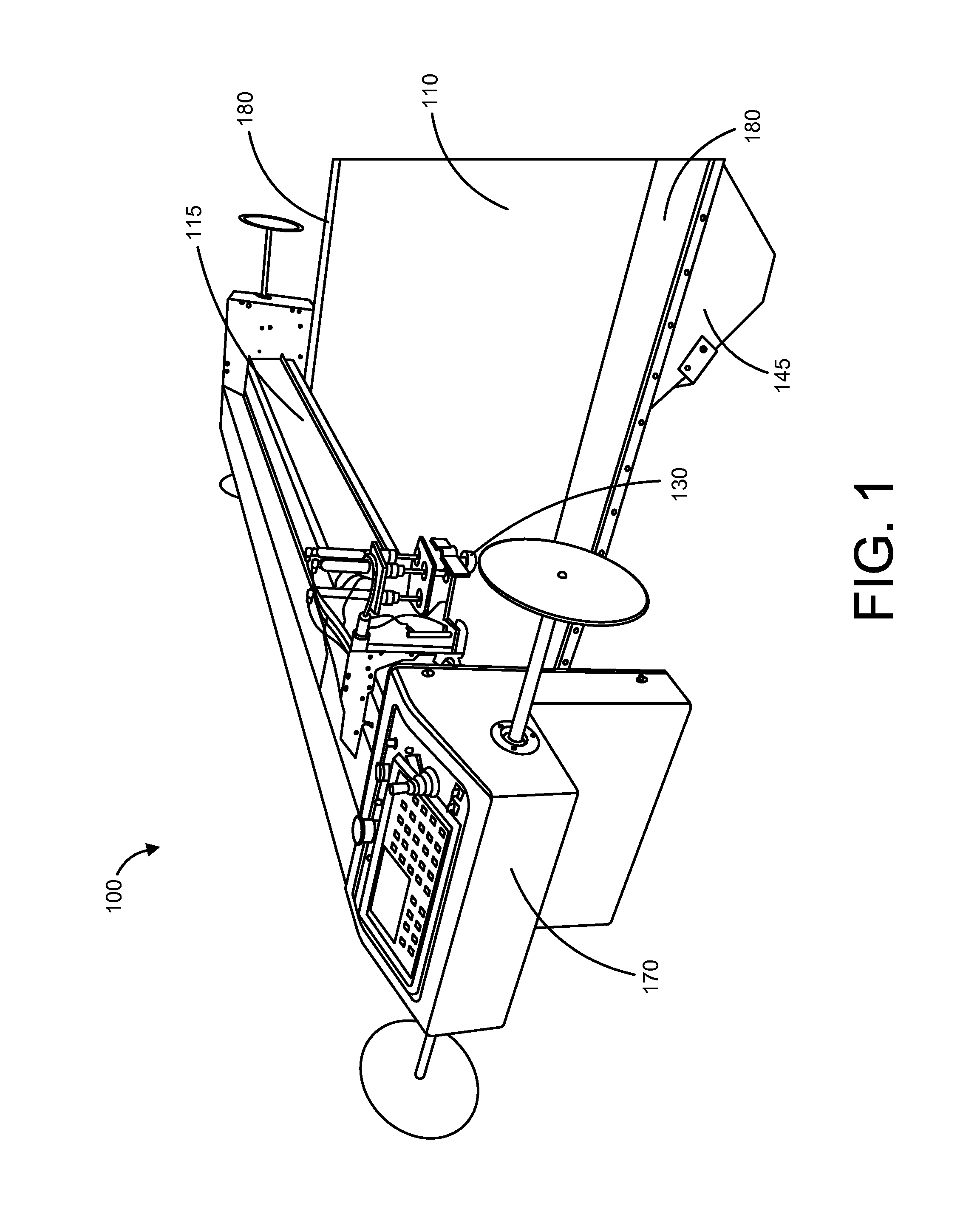
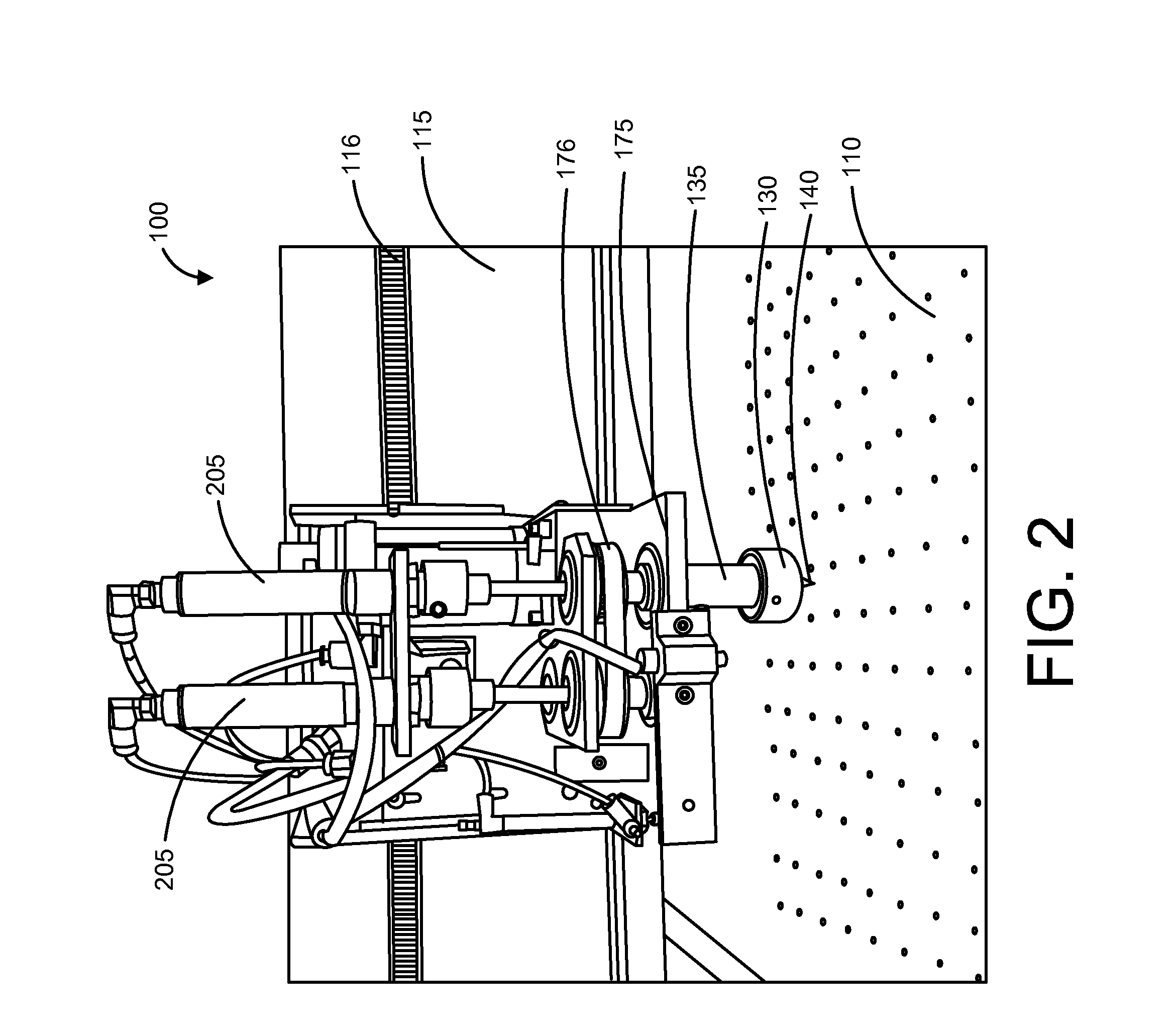
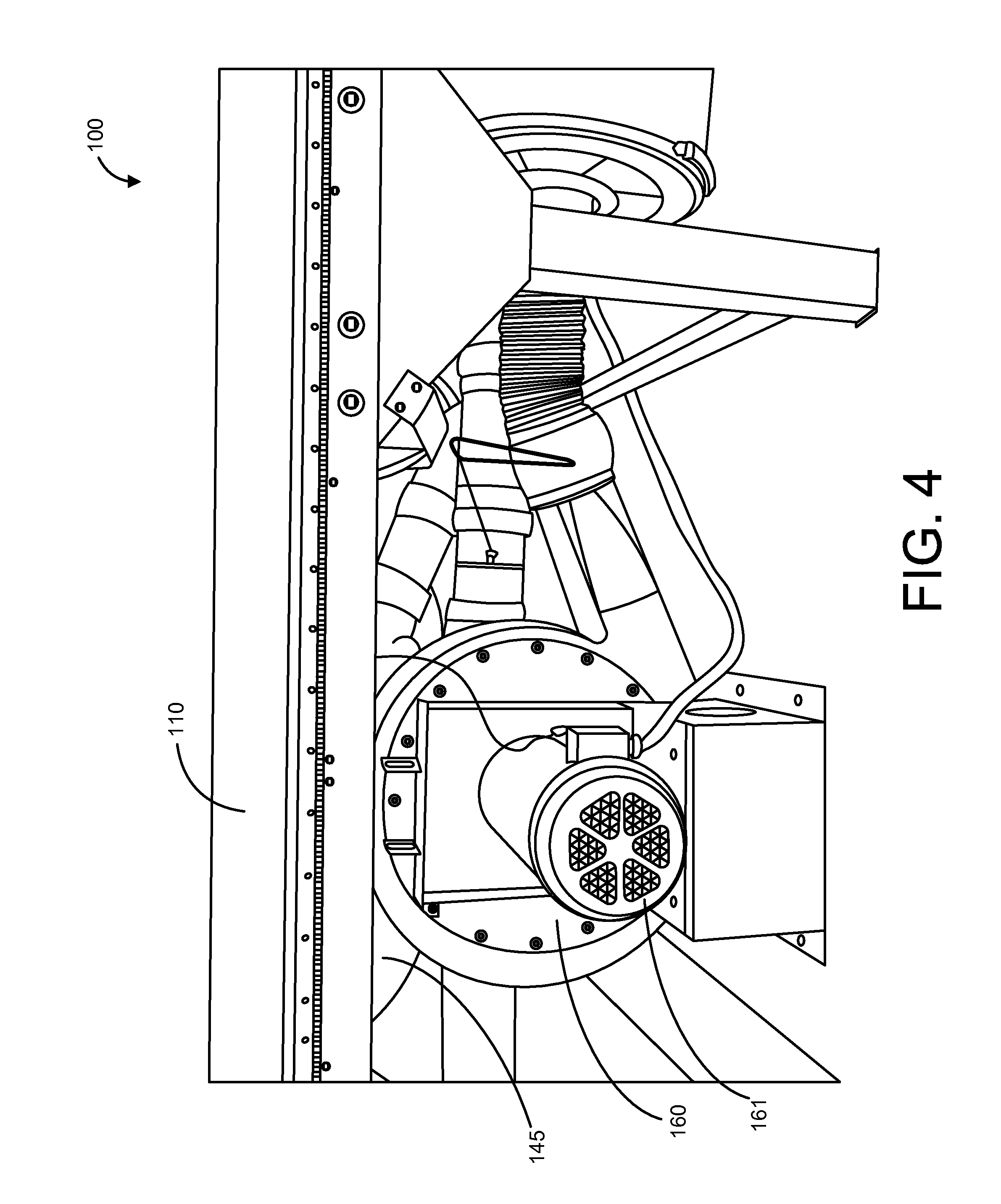
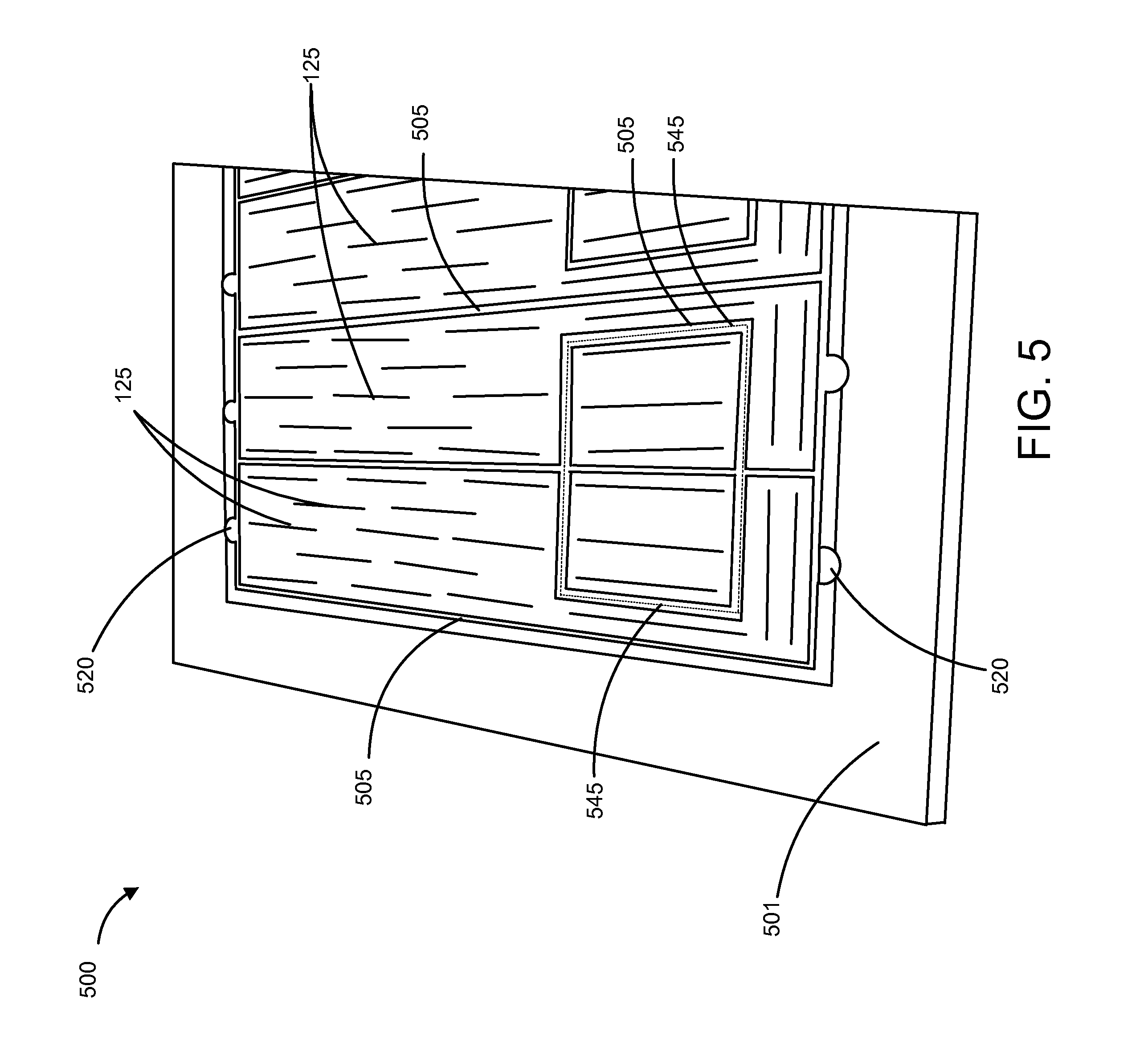
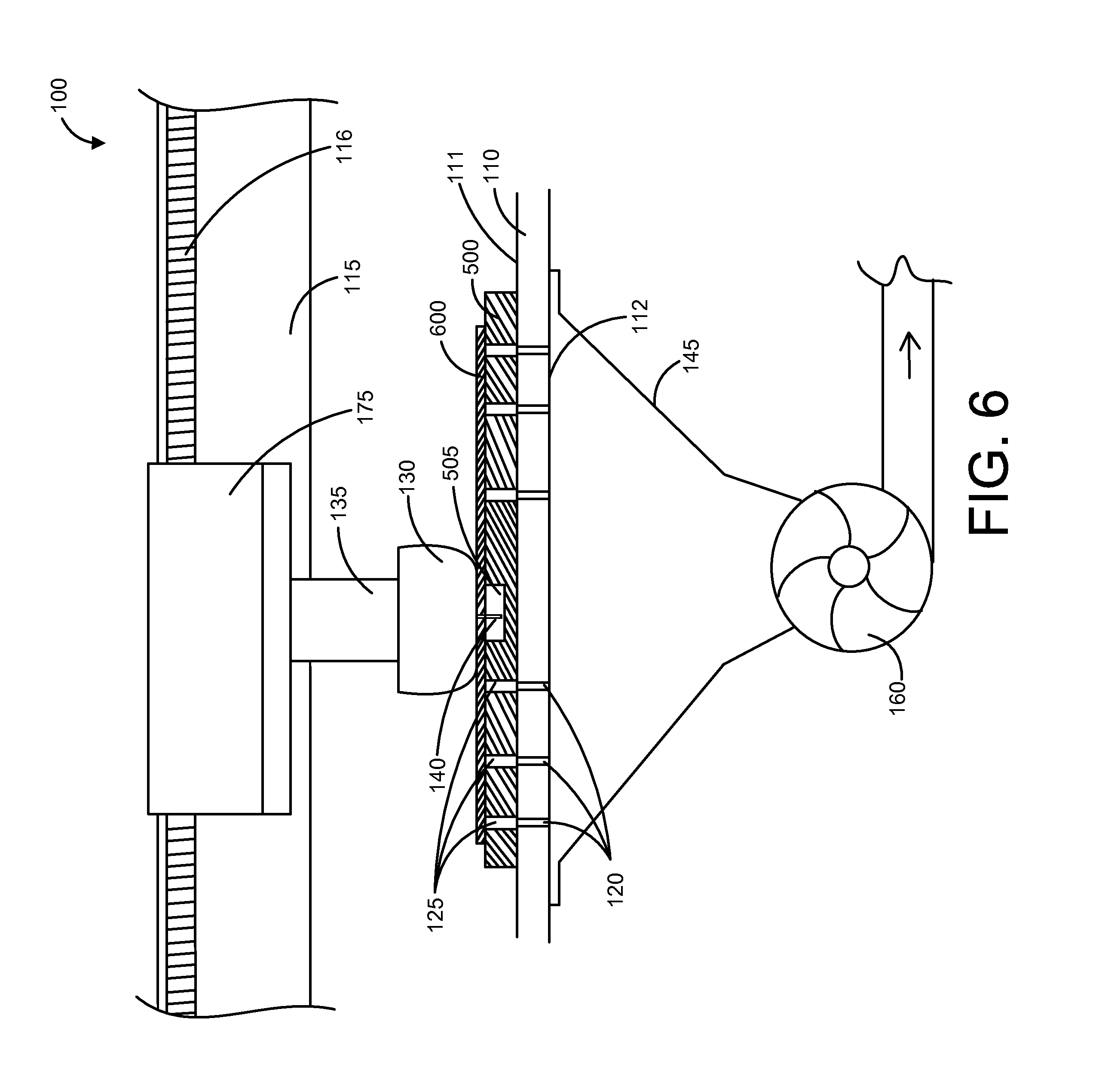
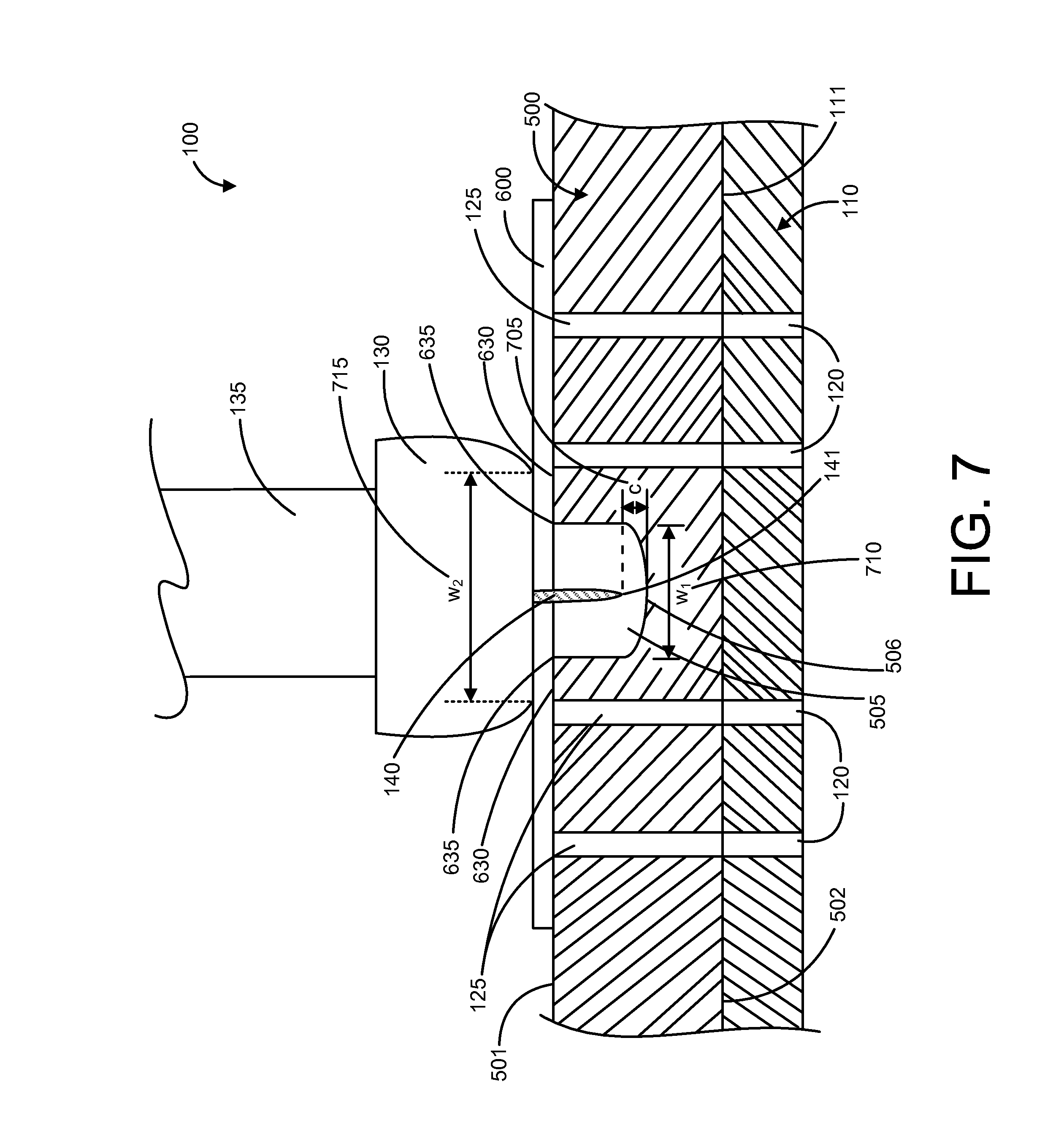
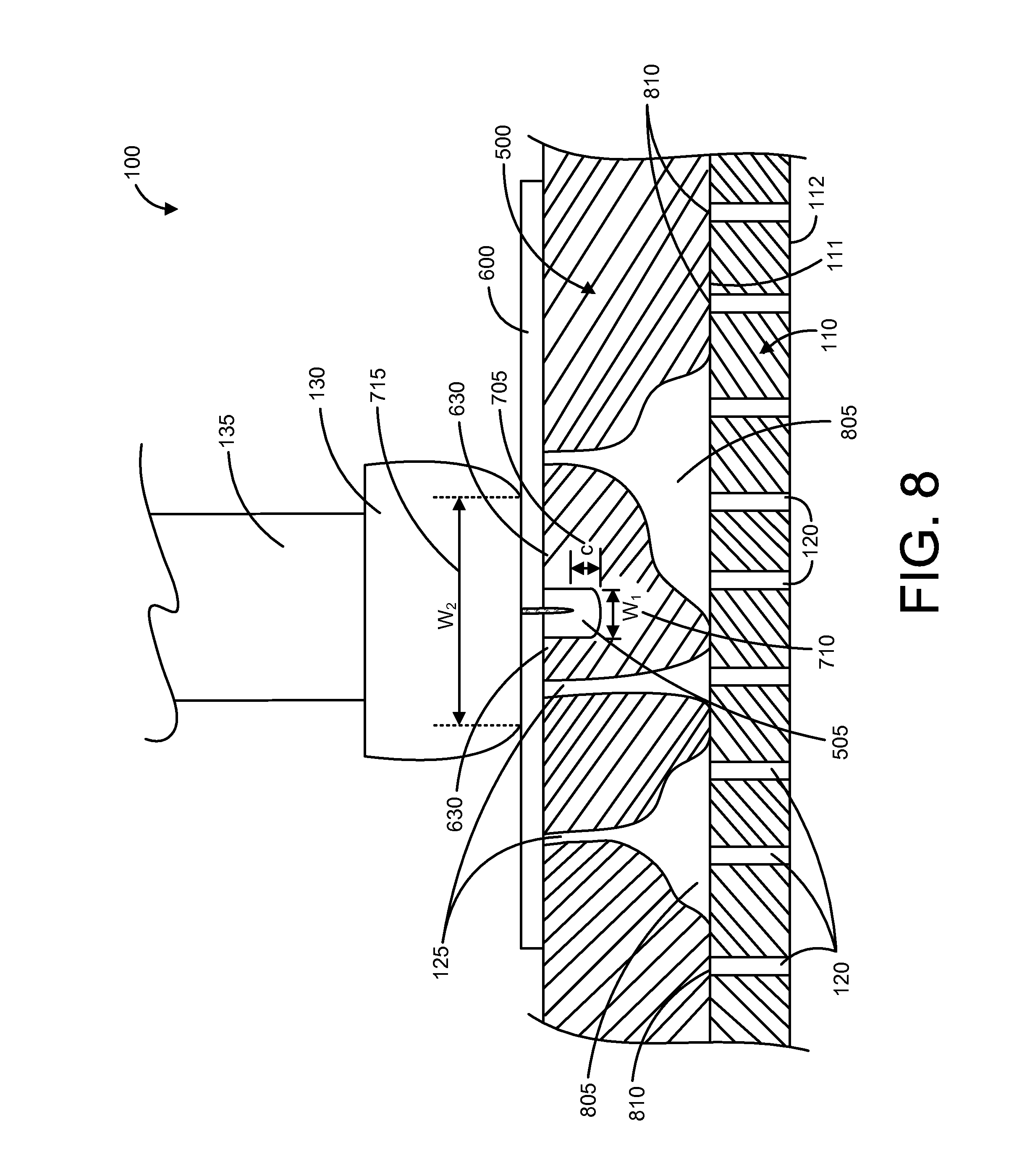
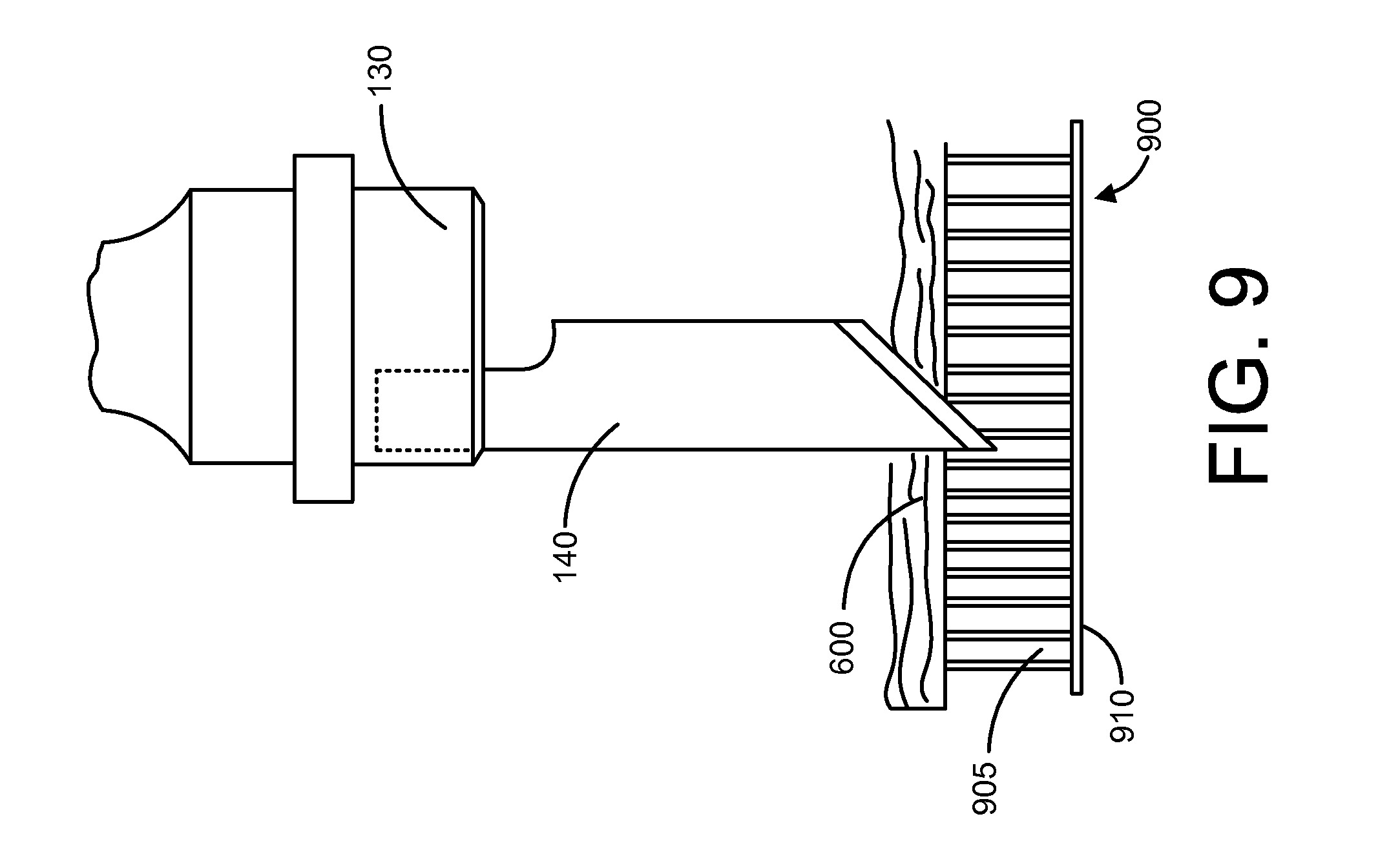
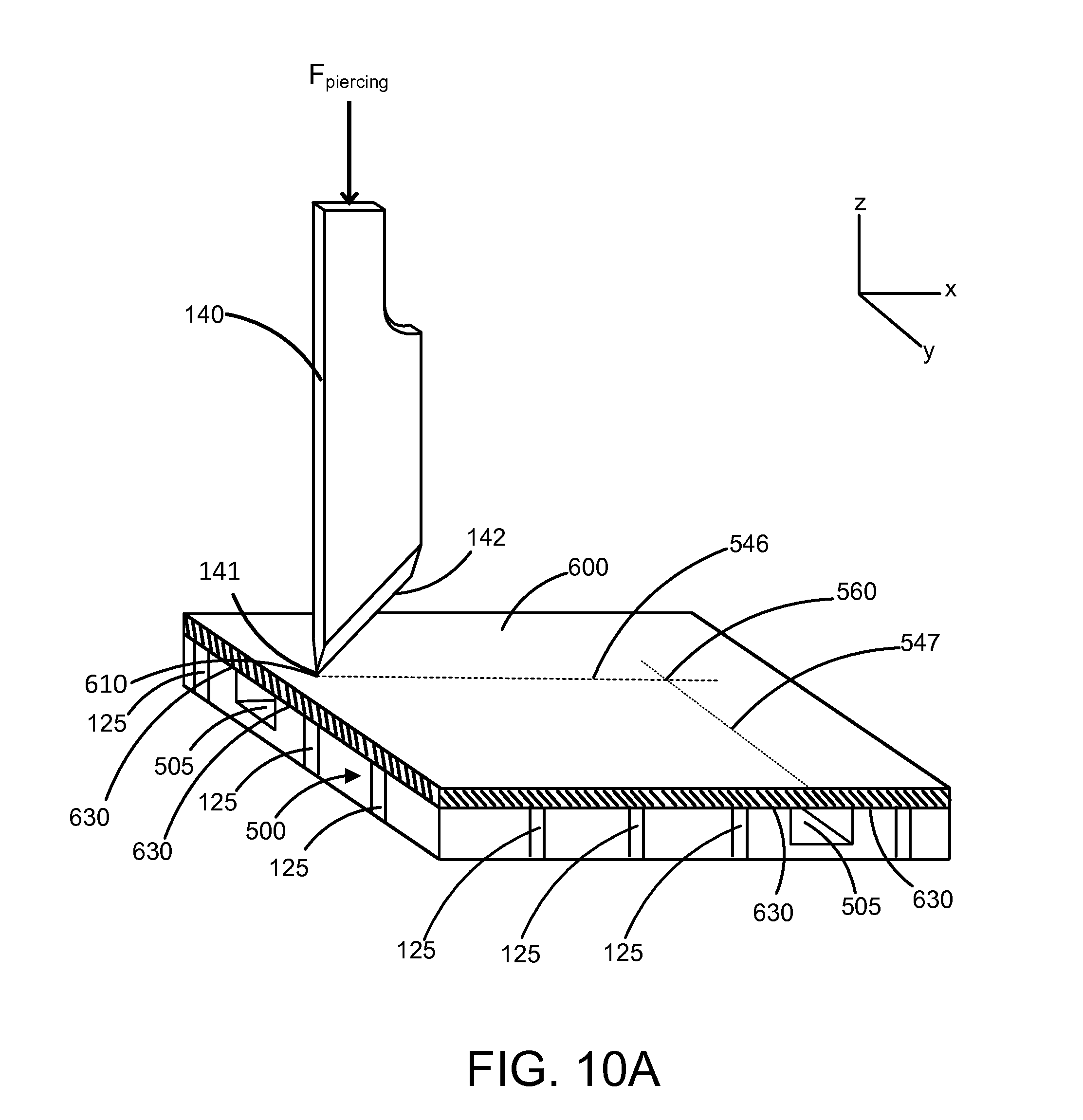
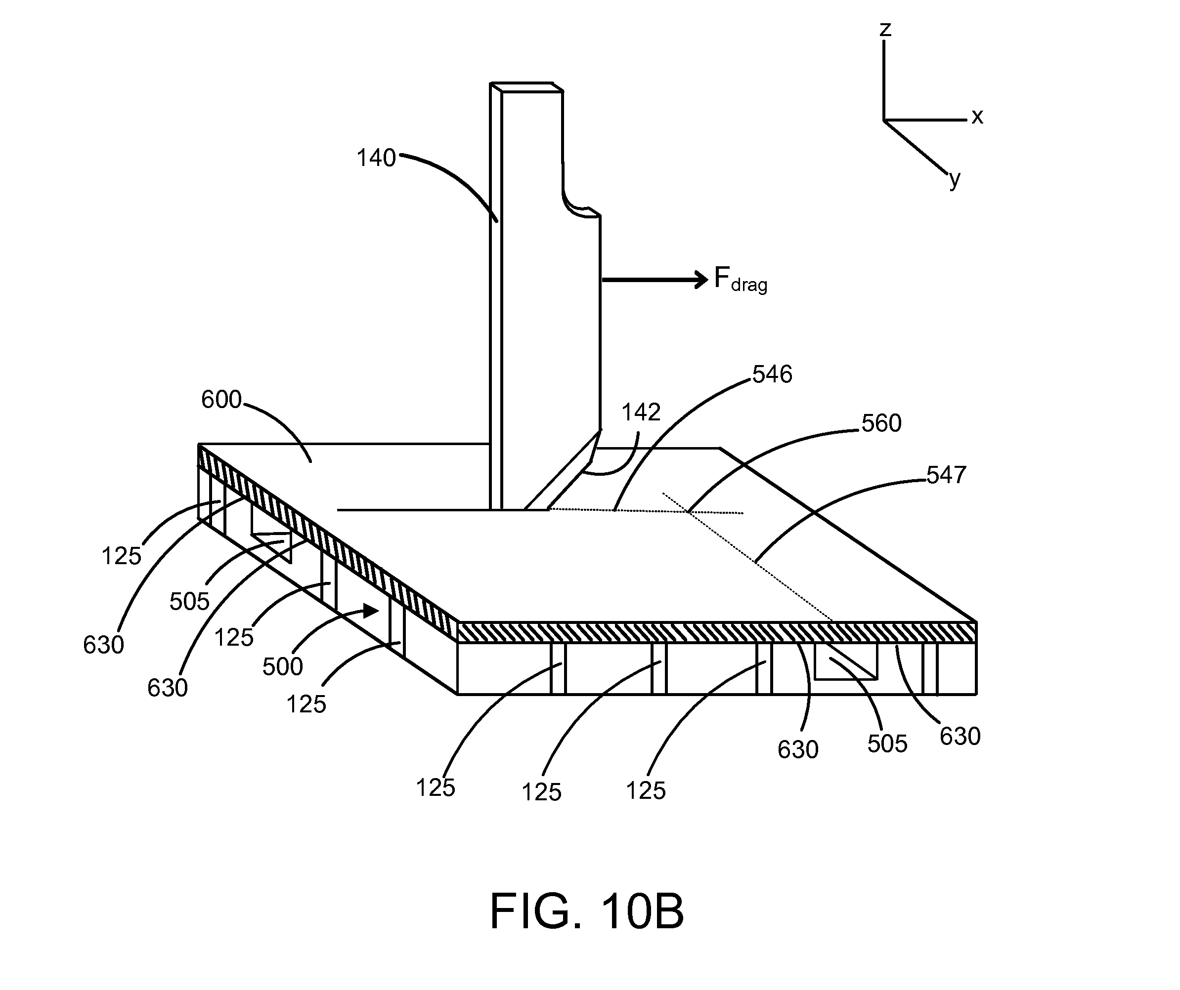
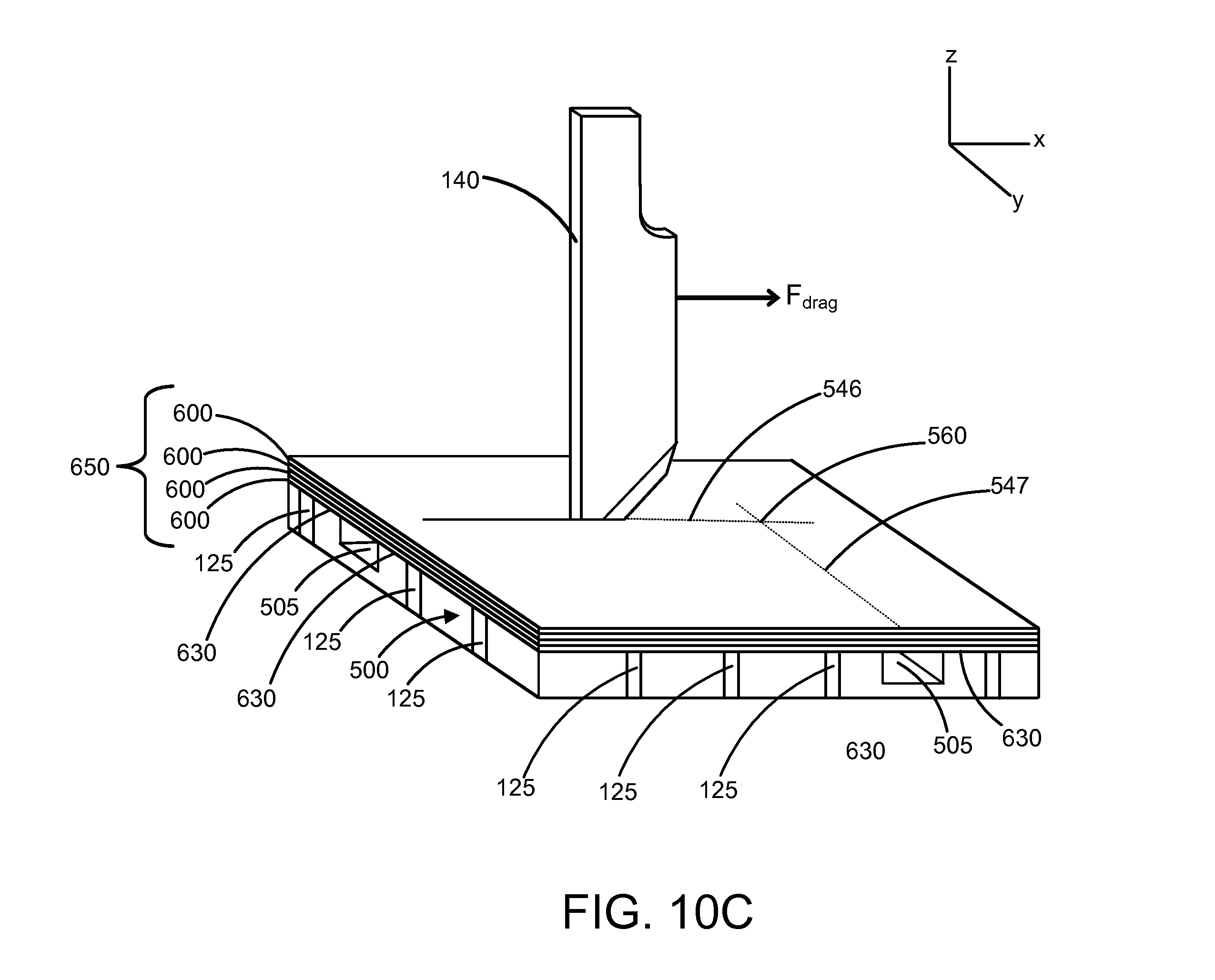
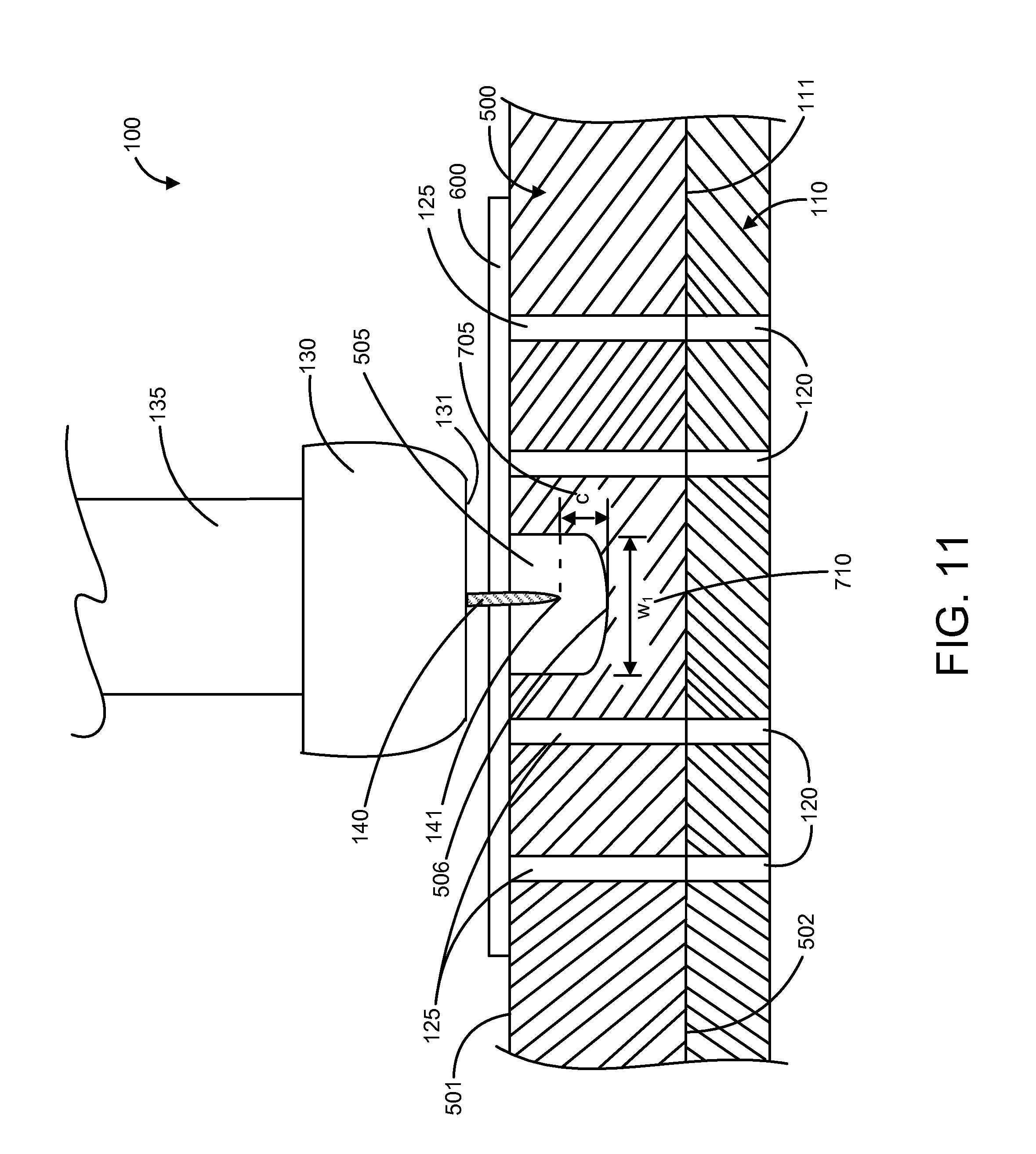
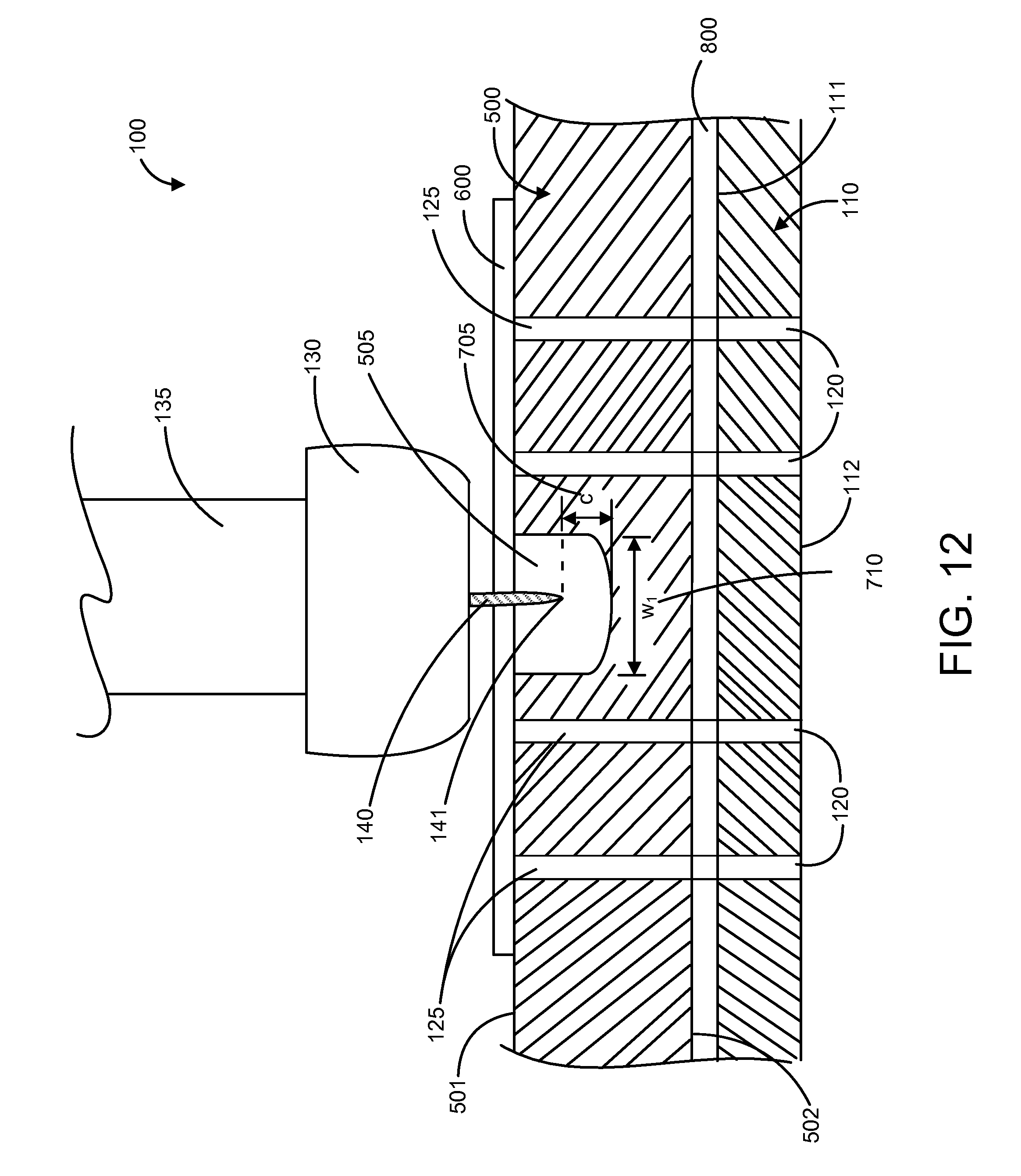
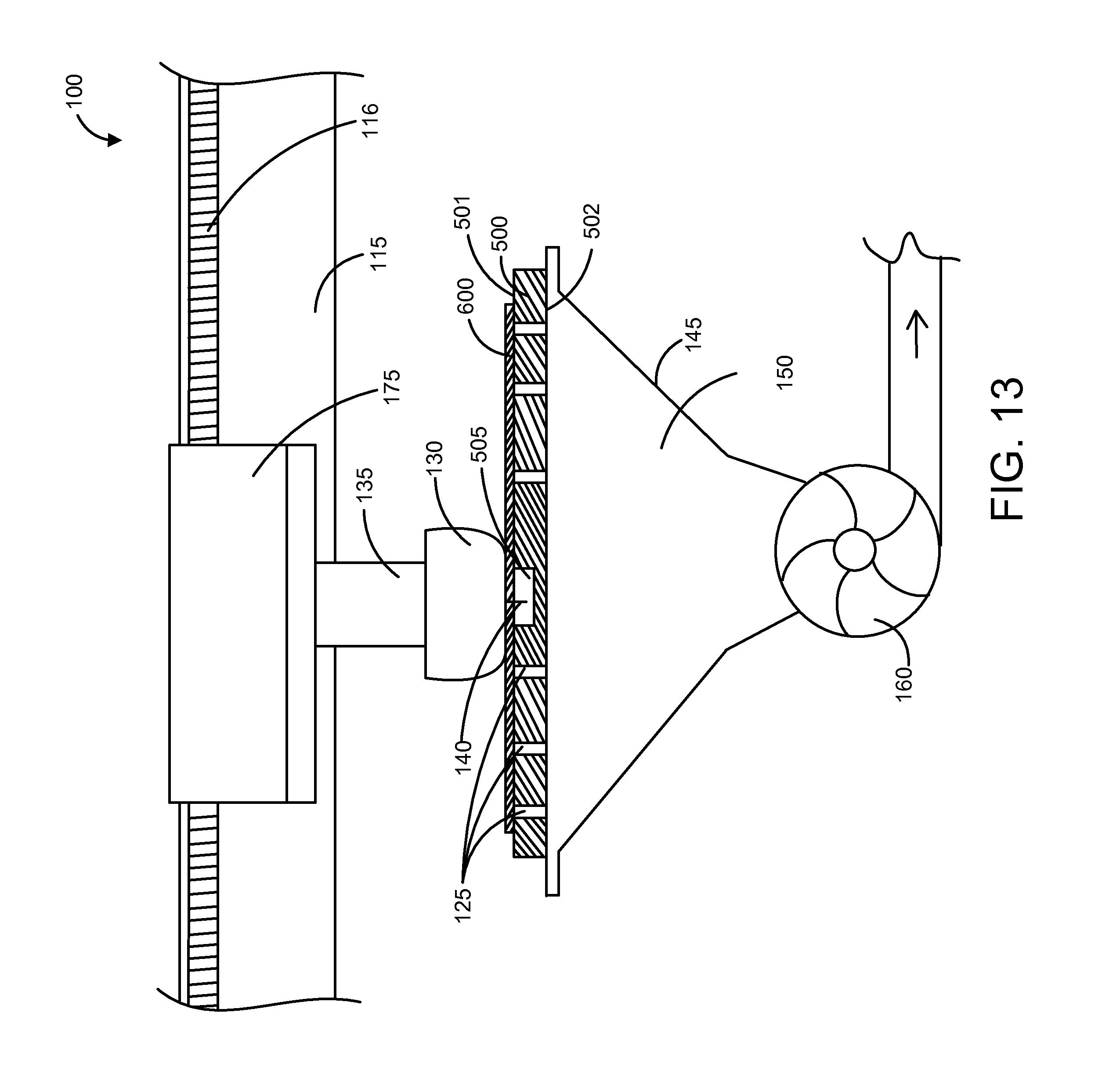
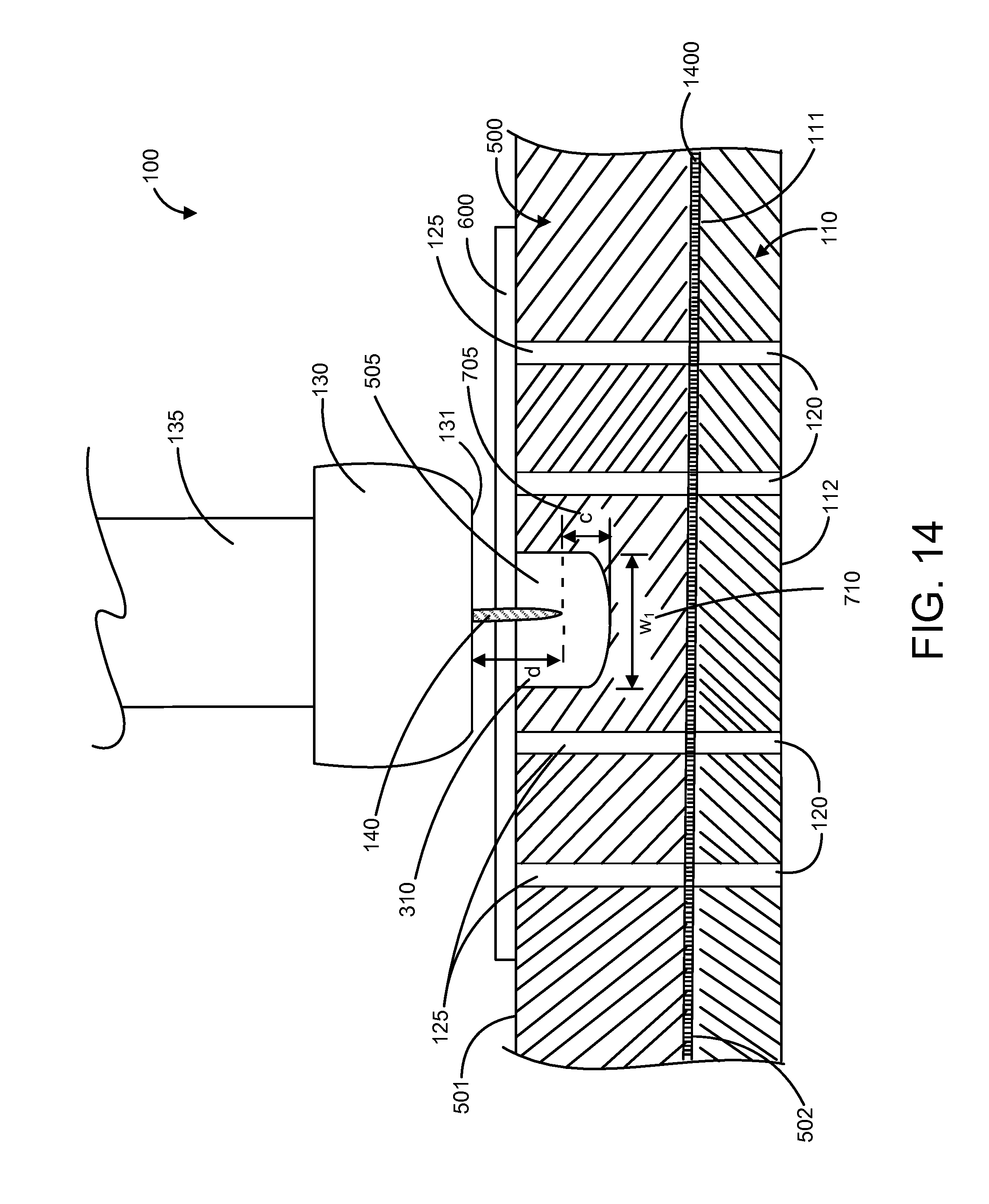
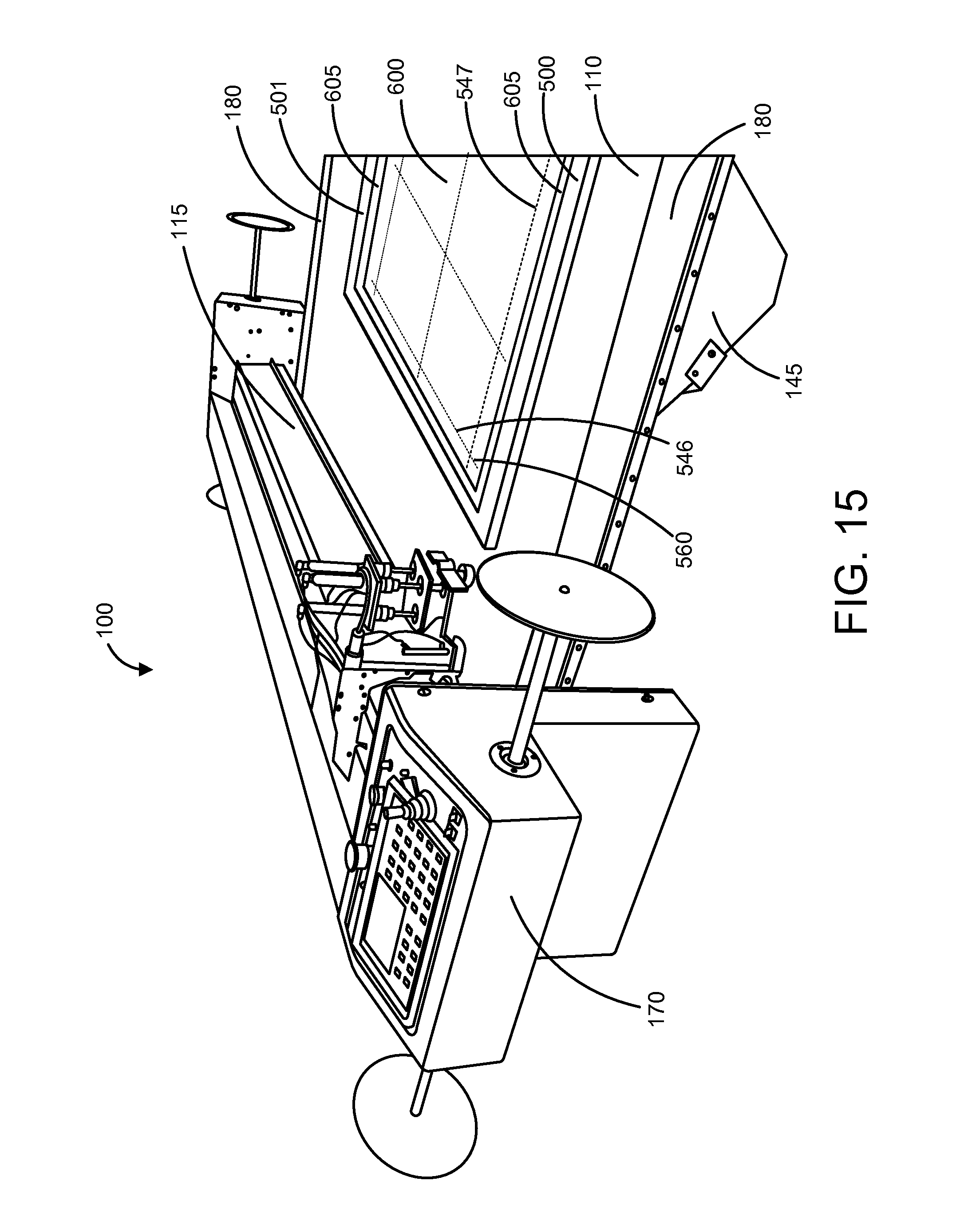
This application claims the benefit of U.S. Provisional Patent Application No. 61/882,973 filed on Sep. 26, 2013, the contents of which is hereby incorporated by reference in its entirety as if fully set forth below. This application is a continuation-in-part of U.S. patent application Ser. No. 14/322,931 filed on Jul. 3, 2014, which claims the benefit of U.S. Provisional Application No. 61/842,937, filed Jul. 3, 2013, and U.S. Provisional Application No. 61/903,337, filed Nov. 12, 2013, each of which is hereby incorporated by reference in its entirety as if fully set forth below. Cutting tables are commonly used in garment factories to facilitate large scale cutting of materials, such as fabrics. Cutting tables are often large, flat surfaces that are well-suited for handling sheets of fabric while patterns are cut from the fabric. To prevent the fabric from moving during a cutting process, the cutting table can be equipped with a vacuum system. The vacuum system can include a plenum located beneath the cutting table, and the plenum can be in fluid communication with small holes or pores in the cutting table. The vacuum system can include a vacuum pump in fluid communication with the plenum. When the vacuum pump is operating, it can draw air through the perforations in the cutting table, into the plenum, and through the vacuum pump. When a sheet of fabric is being cut on the cutting table, operation of vacuum pump produces a partial vacuum in the plenum, which creates a suction force on a top surface of the cutting table, and that suction force prevents the material from moving during the cutting process, thereby improving cutting precision. The solutions described herein provide many advantages over existing methods and apparatuses for cutting materials on a cutting table. For instance, the solutions described herein can significantly increase cutting tool life by reducing wear imparted on a cutting tool by a cutting table surface. The solutions described herein can improve overall cutting efficiency by reducing downtime needed for tooling changes and can reduce process costs by reducing the frequency of cutting tool replacement. The solutions described herein can permit thicker materials to be cut than was possible with conventional approaches. The solutions described herein can also permit multiple layers of materials to be cut simultaneously in a stacked configuration, thereby increasing production rates while simultaneously reducing production costs. A cutting table assembly 100, as shown in The cutting table 110 can be equipped with a vacuum system, which can include a plenum 145 connected to a vacuum pump 160, as shown in The vacuum pump 160 can be placed in fluid communication with the plenum 145, such as with ducting components, as shown in In some examples, the top surface 111 of the cutting table 110 can be made from a durable material such as soapstone, a porous polymer material (e.g. POREX), granite, slate, thermoplastic polycarbonate (e.g. LEXAN), or hardened steel. Preferably, the top surface 111 of the cutting table 110 is made from a material that is not easily damaged by cutting tools (e.g. drag knives or rotary blades) and retains its flatness over time to permit consistent cutting as well as a suitable life expectancy. Cutting a material 600 directly on the cutting table 110 can cause rapid wear of the cutting tool 140, since the cutting table 110 is commonly made of a relatively hard material, and because downward pressure must be applied to the cutting tool 140 to force it against the cutting table to ensure a clean cut through the material being cut. Consequently, direct and prolonged contact of the cutting tool against the cutting table can result in rapid wear of the cutting tool (e.g. drag knife). As the cutting tool 140 wears, its performance deteriorates and the cutting tool will eventually need to be replaced. In other instances, the cutting tool 140 may simply break during use as a result of considerable stresses placed on the cutting tool during cutting, resulting in stress concentrations that result in physical failure of the cutting tool. In either case (i.e. wear or breakage), the cutting tool 140 will need to be replaced with a new blade, and the cutting table assembly 100 will experience downtime while an operator replaces the broken or worn blade. When the cutting tool fails, scrap material 600 often results due to unfinished cuts or unsatisfactory cut quality. This can be particularly common when cutting composite materials (e.g. ballistic sheets) having woven fibers or sheets made of unilateral fibers, since a dull blade may fail to sever high strength fibers (e.g. aramid fibers or ultra-high-molecular-weight polyethylene fibers) completely and may instead pull the fibers from the composite material, thereby producing scrap material that cannot be used for its intended purpose. For many reasons, it is desirable to avoid rapid wear, and frequent replacement, of the cutting tool 140. A prior art method to limit wear of the cutting tool 140 exists, but is useful only for cutting thin textile materials. In the prior art method, the top surface of a cutting table 110 is covered with a bristled 900 material as shown in The prior art method described above and shown in If a user attempts to cut a difficult-to-cut material using the prior art method, the amount of downward force required to puncture and cut the material with a drag knife 140 will result in compression of the bristles 905 and downward deflection of the material being cut, which will decrease cutting precision and, if compression of the bristles 905 exceeds a certain threshold, will result in the drag knife 140 contacting the cutting table 110, causing wear and dulling of the drag knife and possible breakage. Consequently, the prior art method does not permit cutting of certain difficult-to-cut materials while also preventing the drag knife 140 from contacting the cutting table 110. Another downside of the prior art method is that periodic replacement of the bristled material is required. When using a cutting table 110, it is common to cut a common pattern from a series of sheets of fabric. When a common pattern is cut from a series of sheets of fabric positioned on the bristled material, the cutting head 130 will trace the same pathway for each sheet, resulting in the same pathway being traced many times during a production run. The synthetic bristles on the bristled material will become damaged by the repeated passing of the drag knife 140, which is razor sharp, and as a result, the performance and structure of the bristles will be degraded over time. Eventually, the bristled sheet will need to be replaced. In view of the shortcomings of the prior art method, it was desirable to develop a new method that allows a wide variety of materials, such as fabrics, plastics, and composite materials to be cut with efficiency and precision while avoiding unnecessary dulling, breakage, and replacement of the drag knife 140 (e.g. a blade mounted to the cutting head 130). Plastic and composite materials can include dry composites, pre-impregnated composite materials (such as pre-impregnated composite materials manufactured by Polystrand, TechFiber), ultra-high-molecular-weight polyethylene (UHMWPE) fabrics (such as those manufactured by DuPont and BAE), fiberglass-polyester blended fabrics, as well as many others. To avoid unnecessary dulling and breaking of the drag knife 140, a buffer layer 500 can be inserted between the top surface of the cutting table 110 and the material being cut. The buffer layer 500 can prevent the drag knife 140 from contacting the top surface of the cutting table and thereby extend the life of the drag knife and reduce the frequency of drag knife replacement. In another example, where the buffer layer 500 is sufficiently rigid to avoid sagging or deflection during a cutting process, the surface of the cutting table 110 can be removed entirely, and the buffer layer can serve as and replace the cutting table surface, as shown in The buffer layer 500 can include a top side 501 and a bottom side 502. In some examples, during use, as shown in In some examples, the air passages 125 in the buffer layer 500 can be slots in the buffer layer as shown in In one example, the buffer layer 500 can be made of a porous material (e.g. porous polymer material), and the air passages 125 can be established by porosity in the buffer layer so that a separate manufacturing process (e.g. milling, drilling, punching, sawing, carving, etc.) may not be required to create the air passages. In another example, the buffer layer 500 can include a lattice structure, and the air passages can exist between adjacent members of the lattice structure. In yet another example, the buffer layer 500 can be formed by 3D printing. Any suitable 3D printing process can be used to form the buffer layer 500. For instance, a fused deposition modeling (FDM) process can be used to form the buffer layer 500. During the FDM process, a plastic filament or metal wire can be unwound from a coil and supplied to an extrusion nozzle that heats and melts the filament. The extrusion nozzle can move in X, Y, and Z directions by, for example, a computer controlled mechanism employing stepper motors in conjunction with a computer-aided manufacturing (CAM) software package. The buffer layer 500 can be formed by extruding small beads of thermoplastic material (e.g. polycarbonate) to form layers of thermoplastic material. The thermoplastic material can harden shortly after extrusion from the extrusion nozzle, thereby forming a hard, durable buffer layer 500. In another example, 3D printing can be accomplished by stereolithography (SLA), which can be accomplished by depositing thin layers of an ultraviolet curable material sequentially to build the buffer layer 500. As shown in In some examples, the cutting tool 140 can be controlled to execute a series of two or more distinct cutting steps along one or more channels 505 to effectively trace all portions of a cutting pathway 545, thereby facilitating cutting of a pattern from the material 600. For instance, for the cutting pathway 545 shown in dotted lines in For certain materials, such as ballistic sheets 600 made of high strength fibers, it can be desirable for a second pathway 547 of a second cutting step to overlap a first pathway 546 of a first cutting step, as shown in In some examples, as shown in To facilitate easy removal of cut materials 600 from the top surface 501 of the buffer layer 500, the buffer layer can include one or more finger recesses 520, as shown in Each channel 505 can have a depth that is sufficient to prevent the cutting tool 140 from contacting a bottom surface 506 of the channel 505 during a cutting process, such as the cutting process shown in Before cutting in the X or Y directions can occur, the cutting tool 140 must first pierce the material 600 in the Z direction, as shown in By using the buffer layer 500 described herein, the tip 141 of the cutting tool 140 may be exposed to a lower compression force in the z-direction while piercing the material 600, as shown in As shown in In prior art cutting processes, signs of crater wear on the leading edge 142 of the cutting tool 140 is undesirable, since it indicates that the cutting tool is near the end of its useful life. Typically, when crater wear is observed, the cutting tool 140 will be replaced as soon as the operator has an opportunity. However, due to the low piercing force (Fpiercing) experienced by the cutting tool 140 when utilizing the buffer layer 500 as described herein, a cutting tool 140 that displays visible signs of crater wear on its leading edge 142 can continue to be used, often for significant periods of time before failing and with a high level of cutting performance. This extended available life of the cutting tool 140 further adds to the overall increased tool life and cost savings that are possible by using the buffer layer 500 as described herein. The buffer layer 500 can include a support region 630 proximate an upper edge 635 of the channel 505, as shown in To permit the cutting head 130 to apply pressure against the material 600 and in turn against the support regions 630, the cutting head can have a width (w2) 715 that is greater than the width of the channel (w1) 710, as show in As noted above, the cutting head 130 can have a width (w2) 715 that is greater than the width of the channel (w1). For example, the cutting head 130 can have a width (w2) 715 that is about 1-5, 5-15, 15-30, or at least 30% greater than the width (w1) 710 of the channel 505. The additional width (w2−w1) of the cutting head 130 can provide a downward pressure that stabilizes the material 600 against the support regions 630 during the cutting process. The presence of the support regions 630 can greatly diminish downward deflection of the material 600 into the channel 505. As a result of there being little or no downward deflection of the material 600 into the channel 505, a cleaner cut is achieved (e.g. with less collateral damage to the material in the vicinity of the cut). This approach can permit more accurate cutting to be achieved, which yields tighter tolerances and allows certain materials 600, which previously required die cutting or other more costly processes, to be effectively cut on the cutting table 110 quickly and at a low cost. In some examples, as shown in As shown in In one example, the buffer layer 500 can cover most or all of the plurality of the holes 120 in the cutting table 110. The buffer layer 500 can include flat portions that serve as air dams 810, as shown in In another example, the cutting table 110 can include a zoning system for vacuum control. The cutting table 110 can be divided into a plurality of zones (e.g. 2-4, 4-8, or more than 8 zones), and the operator can control (e.g. enable or disable) vacuum independently at each zone. The zoning system can allow for cutting in one zone (e.g. where vacuum is applied) while the operator is simultaneously picking parts (e.g. patterns cut from the material 600) in another zone (e.g. where vacuum is reduced or disabled), which can improve process flexibility and production rates. The zoning system can be computer controlled or manually controlled. In one example, the zoning system can include a separate plenum 145 located beneath each zone and a control valve between each plenum and a common vacuum pump. Opening a first control valve can enable vacuum in a first zone, and closing the first control valve will disable vacuum in the first zone. Similarly, opening a second control valve will enable vacuum in a second zone, and closing the second control valve will disable vacuum in the second zone. If the zoning system is computer controlled, each control valve can be equipped with and actuated by a computer-controlled servomechanism. In another example, the zoning system can include a separate plenum beneath each zone and separate vacuum pump for each zone. Providing power to a first vacuum pump will enable vacuum in a first zone, and disabling power to the first vacuum pump will disable vacuum in the first zone. Similarly, providing power to a second vacuum pump will enable vacuum in a second zone, and disabling power to the second vacuum pump will disable vacuum in the second zone. In some examples, each air passage 125 in the buffer layer 500 can include a filter (e.g. metal mesh, paper, synthetic mesh, or any other suitable type of filter) to restrict cutting remnants from reaching and clogging the plurality of holes 120 in the cutting table 110. The filters can be reusable or disposable. The filters can be removable from the buffer layer 500 to permit cleaning or replacement of the filters. The filters can be cleaned in an ultrasonic cleaner, with compressed air, with a vacuum, with solvents, or by any other suitable method. The filters can cover and attach to the air passages 125 in any suitable way. In one example, the filters can snap into the air passages 125 and can utilize an interference fit to remain in position. In another example, the filters can be attached to the buffer layer 500 using any suitable type of fastener. In yet another example, the buffer layer 500 can include a top portion and a bottom portion, and the filters can be sandwiched between the top and bottom portions. In some examples, the top portion can be attached to the bottom portion by a hinge located along an edge of the buffer layer 500. The hinge can allow for easy separation of the top and bottom portions during insertion or removal of the filters and can also ensure proper alignment of the top and bottom portions when the hinge is in a closed position. The buffer layer 500 can be made of any suitable material. For example, the buffer layer 500 can be made of an engineered wood product (e.g. fiberboard, plywood, particle board), wood, thermoplastic polycarbonate (e.g. LEXAN), composite, bamboo, engineered bamboo, plastic, engineered cellulosic products (e.g. materials made from rye straw, wheat straw, rice straw, hemp stalks, kenaf stalks, or sugar cane), glass, metal, stone, etc. Certain engineered wood products, such as medium density fiberboard (MDF), can be inexpensive and recyclable, which are desirable attributes for the buffer layer 500. Fiberboard can be relatively lightweight, which permits the buffer layer 500 to be easily installed on a cutting table, often by just one person. Consequently, buffer layers 500 made of relatively lightweight fiberboard can reduce labor costs for cutting processes that require a changeover of buffer layers. The plurality of holes 120 in the cutting table 110 can have any suitable size and can be arranged in any suitable array. In one example, the plurality of holes 120 can appear as small perforations arranged in a symmetrical grid on the cutting table 110, as shown in A cutting operation can involve manual or automated cutting of a material 600. In one example shown in A cutting head 130 can be configured to receive and hold the cutting tool 140, as shown in The cutting head 130 can be supported by a carriage assembly 175, as shown in The spindle 135, shown in As shown in In one example, a buffer layer 500 can be adapted for use with a cutting table 110 equipped with a vacuum system. The buffer layer 500 can include a first surface 501 and a second surface 502 opposite the first surface. The second surface of the buffer layer 500 can be adapted to rest against a top surface 111 of a cutting table, as shown in The buffer layer 500 can include a support region 630 proximate a top edge of the channel 505. The support region 630 can be adapted to receive the material 600 to be cut. The support region 630 can be adapted to support the material 600 and resist downward deflection of the material into the channel 505 when downward pressure is applied by the cutting tool 140. In certain examples, the material 600 to be cut can be a carbon-fiber reinforced polymer, a glass-fiber reinforced polymer, or a stack of two or more ballistic sheets, and the material can have a thickness of at least 0.0625 inches. As shown in The buffer layer 500 can include a cavity 805 extending into the second surface of the buffer layer, as shown in A method for cutting a material 600 on a cutting table 110 while preventing a drag knife 140 from contacting a surface 111 of the cutting table can include providing a cutting table and providing a buffer layer 500 positioned on the top surface of the cutting table. The cutting table 110 can include a top surface 111 and a bottom surface 112 opposite the top surface, as show in A ballistic resistant panel can be made of one or more ballistic sheets 600. The term “sheet” or “material” as used herein, can describe one or more layers of any suitable material, such as a polymer, metal, fiberglass, or composite material, or combination thereof. Examples of polymers include aramids, para-aramids, meta-aramids, polyolefins, and thermoplastic polyethylenes. Examples of aramids, para-aramids, meta-aramids include NOMEX, KERMEL, KEVLAR, TWARON, NEW STAR, TECHNORA, HERACRON, and TEIJINCONEX. An example of a polyolefin is INNEGRA. Examples of thermoplastic polyethylenes include TENSYLON from E. I. du Pont de Nemours and Company, DYNEEMA from Dutch-based DSM, and SPECTRA from Honeywell International, Inc., which are all examples of ultra-high-molecular-weight polyethylenes (UHMWPE). Examples of types of glass fibers include A-glass, C-glass, D-glass, E-glass, E-CR-glass, R-glass, S-glass, and T-glass. Other suitable fibers include M5 (polyhydroquinone-diimidazopyridine), which is both high-strength and fire-resistant. A ballistic sheet 600 can be constructed using any suitable manufacturing process, such as extruding, die cutting, forming, pressing, weaving, rolling, etc. The sheet can include a woven or non-woven construction of a plurality of fibers bonded by a resin, such as a thermoplastic polymer, thermoset polymer, elastic resin, or other suitable resin. In one example, the ballistic sheet 600 can include a plurality of aramid bundles of fibers bonded by a resin containing, for example, polypropylene, polyethylene, polyester, or phenol formaldehyde. The plurality of bundles of fibers in the ballistic sheet 600 can be oriented in the same direction, thereby creating a unidirectional fiber arrangement, known as a uni-ply ballistic sheet. In some examples, the ballistic sheet 600 can include fibers that are pre-impregnated with a resin, such as thermoplastic polymer, thermoset polymer, epoxy, or other suitable resin. The fibers can be arranged in a woven pattern or arranged unidirectionally. The resin can be partially cured to allow for easy handling and storage of the ballistic sheet 600 prior to formation of the panel. To prevent complete curing (e.g. polymerization) of the resin before the sheet 600 is incorporated into a ballistic resistant panel, the ballistic sheet may require cold storage. Certain ballistic sheets are described in U.S. Pat. No. 5,437,905, which is hereby incorporated by reference in its entirety. During a manufacturing process, bundles of fibers can be supplied from a plurality of yarn creels. The bundles of fibers can pass through a comb guide where the bundles of fibers are arranged in a parallel orientation and formed into an array and passed over a resin application roller where a resin film, such as a thin polyethylene or polypropylene film or other suitable film, is applied to one side of the array. The bundles of fibers may be twisted or stretched prior to passing over the resin application roller to increase their tenacity. A pre-lamination roller can then press the array of bundles of fibers against the resin film, which is then pressed against a heated plate, which causes the resin film to adhere to the array. After heating, the bundles of fibers and the resin film can be passed through a pair of heated pinch rolls to form a ballistic sheet. The ballistic sheet 600 can then be wound onto a roll. Two ballistic sheets, having unidirectional arrangements of fibers (known as uni-ply), can be bonded together to produce a configuration known as x-ply. X-ply can include a first ballistic sheet 600 and a second ballistic sheet 600, each having a two-dimensional arrangement of unidirectionally-oriented fibers. The second ballistic sheet 600 can be arranged at a 90-degree angle with respect to the first ballistic sheet 600, which is set to a reference angle of 0-degrees. This configuration is known as 0/90 x-ply, where “0” and “90” denote the relative orientations (in degrees) of the bundles of fibers within the first and second ballistic sheets, respectively. The first ballistic sheet 600 can be laminated to the second ballistic sheet 600 in the absence of adhesives or bonding agents. Instead, a first thermoplastic film and second thermoplastic resin film can be bonded to the outer surfaces of the first and second ballistic sheets without penetration of the resin films into the bundles of fibers or through the laminated sheets from one side to the other. Through a process involving heat and pressure, the resin films melt and subsequently solidify to effectively laminate the uni-ply ballistic sheets to each other, thereby producing a 0/90 x-ply configuration. Ballistic sheets constructed from high performance fibers, such as fibers made of aramids, para-aramids, meta-aramids, polyolefins, or ultra-high-molecular-weight polyethylenes, are commercially available from a variety of manufacturers. Several specific examples of commercially-available ballistic sheets made of high performance fibers are provided below. Ballistic sheets are commercially-available in many configurations, including uni-ply, 0/90 x-ply, and 0/90/0/90 double x-ply configurations. Ballistic sheeting material can be ordered in a wide variety of forms, including tapes, laminates, rolls, sheets, structural sandwich panels, and preformed inserts, which can all be cut to size during a manufacturing process. TechFiber, LLC, located in Arizona, manufactures a variety of ballistic sheets made of aramid fibers that are sold under the trademark K-FLEX. One version of K-FLEX is made with KEVLAR fibers having a denier of about 1000 and a pick count of about 18 picks per inch. K-FLEX can have a resin content of about 15-20%. Different versions of K-FLEX may contain different resins. For instance, a first version of K-FLEX can include a resin (e.g. a polyethylene resin) with a melting temperature of about 215-240 degrees F., a second version of K-FLEX can include a resin with a melting temperature of about 240-265 degrees F., a third version of K-FLEX can include a resin with a melting temperature of about 265-295 degrees F., and a fourth version of K-FLEX can include a resin with a melting temperature of about 295-340. K-FLEX is available in uni-ply, 0/90 x-ply, and 0/90/0/90 double x-ply configurations. TechFiber, LLC also manufactures a variety of unidirectional ballistic sheets made of aramid fibers that are sold under the trademark T-FLEX. Certain versions of T-FLEX can have a resin content of about 15-20% and can include aramid fibers such as TWARON fibers (e.g. model number T765). Different versions of T-FLEX may contain different resins. For instance, a first version of T-FLEX can include a resin (e.g. a polyethylene resin) with a melting temperature of about 215-240 degrees F., a second version of T-FLEX can include a resin with a melting temperature of about 240-265 degrees F., a third version of T-FLEX can include a resin with a melting temperature of about 265-295 degrees F., and a fourth version of T-FLEX can include a resin with a melting temperature of about 295-340 degrees F. T-FLEX is available in uni-ply, 0/90 x-ply, and 0/90/0/90 double x-ply configurations. Polystrand, Inc., located in Colorado, manufactures a variety of unidirectional ballistic sheets made of aramid fibers that are sold under the trademark THERMOBALLISTIC. One version of THERMOBALLISTIC ballistic sheets are sold as product number TBA-8510 and include aramid fibers with a pick count of about 12.5 picks per inch. Other versions of THERMOBALLISTIC ballistic sheets are sold as product numbers TBA-8510X and TBA-9010X and include aramid fibers (e.g. KEVLAR fibers) and have a 0/90 x-ply configuration. The resin content of the THEMROBALLISTIC ballistic sheets can be about 10-20% or 15-20%. Different versions of THERMOBALLISTIC ballistic sheets may contain different resins. For instance, a first version of THERMOBALLISTIC ballistic sheets can include a resin with a melting temperature of about 225-255 degrees F., a second version of THERMOBALLISTIC ballistic sheets can include a resin (e.g. a polypropylene resin) with a melting temperature of about 255-295 degrees F., a third version of THERMOBALLISTIC ballistic sheets can include a resin (e.g. a polypropylene resin) with a melting temperature of about 295-330 degrees F., a fourth version of THERMOBALLISTIC ballistic sheets can include a resin with a melting temperature of about 330-355 degrees F., and a fifth version of THERMOBALLISTIC ballistic sheets can include a resin with a melting temperature of about 355-375 degrees F. One version of THERMOBALLISTIC ballistic sheets can include a polypropylene resin. THERMOBALLISTIC ballistic sheets are available in uni-ply, 0/90 x-ply, and 0/90/0/90 double x-ply configurations. E. I. du Pont de Nemours and Company (DuPont), located in Delaware, manufactures a ballistic sheet material made of ultra-high-molecular-weight polyethylene fabric that is sold under the trademark TENSYLON. A Material Data Safety Sheet was prepared on Feb. 2, 2010 for a material sold under the tradename TENSYLON HTBD-09-A (Gen 2) by BAE Systems TENSYLON High Performance Materials. The Material Safety Data Sheet is identified as TENSYLON MSDS Number 1005, is publicly available, and is hereby incorporated by reference in its entirety. The ballistic sheets are marketed as being lightweight and cost-effective and boast low back face deformation, excellent flexural modulus, and superior multi-threat capability over other commercially available ballistic sheets. The ballistic sheet material can be purchased on a roll and can be cut into ballistic sheets having a size and shape dictated by an intended application. Honeywell International, Inc., headquartered in New Jersey, manufactures a variety of ballistic sheets made of aramid fibers that are sold under the trademark GOLD SHIELD. One version of GOLD SHIELD ballistic sheets are sold under product number GN-2117 and are available in 0/90 x-ply configurations and have an areal density of about 3.24 ounces per square yard. To increase production rates, it can be desirable to cut a pattern from two or more sheets of material 600 simultaneously. This can be accomplished by stacking two or more ballistic sheets prior to cutting the sheets. Cutting can be accomplished on a cutting table 110 with any suitable cutting tool 140, such as a laser, blade, drag knife, rotary knife, or die cutter. In one example the cutting tool 140 can be a drag knife mounted to a computer-controlled gantry. When a drag knife is used, a downward cutting force from the drag knife is applied against the stack of ballistic sheets and, in turn, against the top surface of the cutting table (or protective layer 800 of, for example, LEXAN, that covers and protects the top surface of the cutting table). If two or more types of materials 600, such as ballistic sheets, are being cut simultaneously in a stack 650, the resulting cut quality of each ballistic sheet can depend on the arrangement of the ballistic sheets within the stack. Certain types of ballistic sheets that are less stiff suffer poor cut quality if placed on top of the stack 650. For instance, ballistic sheets that are less stiff may suffer poor cut quality, such as fraying along edges or fibers pulling from the sheets by the drag knife 140, which can compromise performance and structure of the cut sheets. Through experimentation, it has been discovered that bounding a ballistic sheet 600 that is less stiff with ballistic sheets that are more stiff can provide better cut quality along an edge of the ballistic sheet that is less stiff and produce significantly less fraying or pulling of fibers at the edge of the less stiff ballistic sheet. In one example, a grouping of one or more ballistic sheets that are less stiff can be bounded on a top surface by a grouping of one or more ballistic sheets that are stiffer. Specifically, a stack 650 of ballistic sheets 600 that is suitable for cutting on a cutting table can include a first grouping of one or more stiffer ballistic sheets on top of a second grouping of one or more less stiff ballistic sheets. In another example, a grouping of one or more ballistic sheets 600 that are less stiff can be bounded on a top surface and a bottom surface by grouping of one or more ballistic sheets that are stiffer. Specifically, a stack 650 of ballistic sheets 600 that is suitable for cutting on a cutting table can include a first grouping of one or more stiffer ballistic sheets, a second grouping of one or more less stiff ballistic sheets, and a third grouping of one or more stiffer ballistic sheets. The flexibility of commercially available ballistic sheets 600 varies. In relative terms, K-FLEX ballistic sheets can be less stiff than THERMOBALLISTIC ballistic sheets. K-FLEX ballistic sheets can have a stiffness similar to fabric, whereas THERMOBALLISTIC ballistic sheets can have a stiffness similar to a paper business card. When cutting one or more K-FLEX ballistic sheets, cutting performance can be enhanced by grouping the one or more K-FLEX ballistic sheets with one or more THERMOBALLISTIC ballistic sheets, either on a top side only or on both a top and bottom side of the one or more K-FLEX ballistic sheets. These groupings of ballistic sheets can provide cleaner cuts with less fraying along edges of the K-FLEX ballistic sheets. Reducing fraying along edges of the cut sheets can help ensure that the performance of the sheets is not degraded and that a ballistic apparatus constructed from the ballistic sheets performs as intended. Examples of stacks 650 of ballistic sheets 600 suitable for cutting on a cutting table 110 include the following configurations, where the first listed grouping in each stack 650 is in closest proximity to the top surface 111 of the cutting table 110, and the last listed grouping in each stack is farthest from the top surface of the cutting table: 1-6 THERMOBALLISTIC 0/90 x-ply ballistic sheets, 1-10 K-FLEX 0/90 x-ply ballistic sheets, 1-6 THERMOBALLISTIC 0/90 x-ply ballistic sheets; 1-5 THERMOBALLISTIC 0/90 x-ply ballistic sheets, 1-10 K-FLEX 0/90 x-ply ballistic sheets, 1-5 THERMOBALLISTIC 0/90 x-ply ballistic sheets; 1-4 THERMOBALLISTIC 0/90 x-ply ballistic sheets, 1-10 K-FLEX 0/90 x-ply ballistic sheets, 1-4 THERMOBALLISTIC 0/90 x-ply ballistic sheets; 1-3 THERMOBALLISTIC 0/90 x-ply ballistic sheets, 1-10 K-FLEX 0/90 x-ply ballistic sheets, 1-3 THERMOBALLISTIC 0/90 x-ply ballistic sheets; 1-2 THERMOBALLISTIC 0/90 x-ply ballistic sheets, 1-10 K-FLEX 0/90 x-ply ballistic sheets, 1-2 THERMOBALLISTIC 0/90 x-ply ballistic sheets; 1 THERMOBALLISTIC 0/90 x-ply ballistic sheets, 1-10 K-FLEX 0/90 x-ply ballistic sheets, 1 THERMOBALLISTIC 0/90 x-ply ballistic sheets; 6 THERMOBALLISTIC 0/90 x-ply ballistic sheets, 10 K-FLEX 0/90 x-ply ballistic sheets, 6 THERMOBALLISTIC 0/90 x-ply ballistic sheets; 6 THERMOBALLISTIC 0/90 x-ply ballistic sheets, 8 K-FLEX 0/90 x-ply ballistic sheets, 6 THERMOBALLISTIC 0/90 x-ply ballistic sheets; or 1 or more THERMOBALLISTIC 0/90 x-ply ballistic sheets, 1 or more K-FLEX 0/90 x-ply ballistic sheets, 1 or more THERMOBALLISTIC 0/90 x-ply ballistic sheets. Additional examples of stacks 650 of ballistic sheets 600 suitable for cutting on a cutting table are provided below, where a first plurality of ballistic sheets (e.g. one or more K-FLEX 0/90 x-ply ballistic sheets) are bounded by a second plurality of ballistic sheets (e.g. one or more THERMOBALLISTIC 0/90 x-ply ballistic sheets). In the following examples, the first listed grouping in each stack is in closest proximity to the top surface of the cutting table: 1-6 K-FLEX 0/90 x-ply ballistic sheets, 1-6 THERMOBALLISTIC 0/90 x-ply ballistic sheets; 1-4 K-FLEX 0/90 x-ply ballistic sheets, 1-6 THERMOBALLISTIC 0/90 x-ply ballistic sheets; 2-4 K-FLEX 0/90 x-ply ballistic sheets, 3-6 THERMOBALLISTIC 0/90 x-ply ballistic sheets; 3-4 K-FLEX 0/90 x-ply ballistic sheets; 4-6 THERMOBALLISTIC 0/90 x-ply ballistic sheets; 3 K-FLEX 0/90 x-ply ballistic sheets, 6 THERMOBALLISTIC 0/90 x-ply ballistic sheets; 4 K-FLEX 0/90 x-ply ballistic sheets, 6 THERMOBALLISTIC 0/90 x-ply ballistic sheets. In some examples, the stack 650 of materials 600, such as a stack of ballistic sheets 600, can be cut without using a buffer layer 500, as shown in As shown in The buffer layer 500 can be equipped for use with a cutting table 110 equipped with a vacuum system. The buffer layer 500 can include a first surface and a second surface opposite the first surface. The second surface of the buffer layer 500 can be adapted to rest against a top surface 111 of the cutting table 110. The first surface of the buffer layer 500 can be adapted to receive a material to be cut 600. The buffer layer 500 can include a channel 505 disposed in the first surface of the buffer layer. The channel 505 can correspond to a pattern to be cut from the material 600. The channel 505 can have a depth that is configured to provide a clearance depth 705 between a tip 141 of a cutting tool 140 associated with the cutting table 110 and a bottom surface 506 of the channel. The buffer layer 500 can include a plurality of air passages 125 extending from the first surface of the buffer layer to the second surface of the buffer layer. The plurality of air passages 125 can be adapted to permit airflow through the buffer layer 500 from the first surface of the buffer layer to the second surface of the buffer layer and into the vacuum system of the cutting table 110. The buffer layer 500 can include a support region 630 proximate a top edge of the channel 505 in the buffer layer. The support region 630 can be adapted to receive the material 600 to be cut. The support region 630 can be adapted to support the material 600 and resist downward deflection of the material into the channel 500 when downward pressure is applied against the material by the tip 141 of the cutting tool 140 during a piercing process, as shown in The cutting table assembly 100 can be equipped with a cutting head 130 from which the cutting tool 140 extends. In some examples, a width of the channel 505 in the buffer layer 500 can be less than a width of the cutting head 130. The clearance depth 705 between the tip 141 of the cutting tool 140 and the bottom surface 506 of the channel 505 can be at least 0.02 inch. In some examples, the buffer layer 500 can be made of an engineered wood product. In other examples, the buffer layer 500 can be a 3D printed buffer layer. The buffer layer 500 can include a cavity 805 extending into the second surface of the buffer layer, where the cavity is adapted to permit a first air passage of the plurality of air passages 125 to be in fluid communication with a first hole of the plurality of holes 120 in the cutting table 110 when the first air passage and the first hole are misaligned. In some examples, the buffer layer 500 can include a filter layer proximate the second surface of the buffer layer, and the filter layer can be configured to capture cutting remnants. The material 600 to be cut can be, for example, a carbon-fiber reinforced polymer, a glass-fiber reinforced polymer, or a stack of two or more ballistic sheets. The buffer layer 500 can include a finger recess 520 in the first surface of the buffer layer. The finger recess 520 can be configured to allow a finger of a user to be inserted beneath an edge of the material 600 to be cut to permit the material to be lifted more easily from the buffer layer when the vacuum system is operating. A method for cutting a material 600 on a cutting table 110 while preventing a cutting tool 140 from contacting a top surface 111 of the cutting table can include several steps. The method can include providing a cutting table 110 having a top surface 111 and a bottom surface 112 opposite the top surface. The cutting table 110 can include plurality of holes 120 extending from the top surface 111 to the bottom surface 112. The cutting table 110 can include a plenum 145 in fluid communication with the bottom surface 111 of the cutting table 110 and a vacuum pump 160 in fluid communication with the plenum 145. The vacuum pump 160 can be adapted to produce a partial vacuum in the plenum 145 while operating and, as a result of the partial vacuum, can draw air downward through the plurality of holes 120 in the cutting table 110. The method can include providing a buffer layer 500 positioned on the top surface 111 of the cutting table 110. The buffer layer 500 can include a first surface and a second surface opposite the first surface. The second surface of the buffer layer 500 can be adapted to rest against the top surface 111 of the cutting table 110. The first surface of the buffer layer 500 can be adapted to receive the material to be cut 600. The buffer layer 500 can include a channel 505 in the first surface of the buffer layer. The channel 505 can correspond to a pattern to be cut from the material 600. The channel 505 can have a depth adapted to provide a clearance depth 705 between a cutting tool 140 and a bottom surface 506 of the channel while the pattern is being cut from the material 600. The buffer layer 500 can include a plurality of air passages 125 extending from the first surface of the buffer layer to the second surface of the buffer layer. The plurality of air passages 125 can be adapted to permit airflow through the buffer layer 500 and into the plurality of holes 120 in the cutting table 110 when the vacuum system is operating. The method can include performing a first cutting step along a first cutting pathway 546 and performing a second cutting step along a second cutting pathway 547. The first cutting pathway 546 can correspond to a first channel 505 in the buffer layer 500, and the second cutting pathway 547 can correspond to a second channel 505 in the buffer layer 500. As shown in A sacrificial protective layer 800, as shown in A method for cutting a stack 650 of two or more ballistic sheets 600 simultaneously on a cutting table 110 can include several steps. The method can include providing the cutting table 110. The cutting table 110 can include a top surface 111 and a bottom surface 112 opposite the top surface, a cutting tool 140 movable relative to the top surface of the cutting table, a plurality of holes 120 extending from the top surface to the bottom surface of the cutting table, a plenum 145 in fluid communication with the bottom surface of the cutting table, and a vacuum pump 160 in fluid communication with the plenum. The vacuum pump 160 can be adapted to produce a partial vacuum in the plenum while operating and can draw air through the plurality of holes 120 in the top surface of the cutting table. The method can include providing the stack 650 of ballistic sheets 600 to be cut. The stack 650 of ballistic sheets 600 can include a first grouping of one or more ballistic sheets and a second grouping of one or more ballistic sheets. The one or more ballistic sheets in the first grouping can be stiffer than the one or more ballistic sheets in the second grouping of ballistic sheets. The stack 650 of ballistic sheets 600 can be arranged with the first grouping of ballistic sheets positioned on top of the second grouping of ballistic sheets. The method can include providing a protective layer 800 positioned on the top surface 111 of the cutting table 110. The protective layer 800 can include a first surface and a second surface opposite the first surface. The second surface of the protective layer 800 can be adapted to rest against a top surface 111 of the cutting table 110. The first surface of the protective layer 800 can be adapted to receive and support the stack 650 of ballistic sheets to be cut 600. The protective layer 800 can include a plurality of air passages 805 extending from the first surface of the protective layer to the second surface of the protective layer. The plurality of air passages 805 can be adapted to permit airflow through the protective layer 800 from the first surface of the protective layer to the second surface of the protective layer and into the plenum 145 that is fluidly connected to the bottom surface 112 of the cutting table 110. In some examples, the stack 650 of ballistic sheets 600 can include a third grouping of one or more ballistic sheets. The one or more ballistic sheets in the third grouping can be more stiff than the one or more ballistic sheets in the second grouping of ballistic sheets. The stack 650 of ballistic sheets 600 can be arranged with the third grouping of ballistic sheets positioned beneath the second grouping of ballistic sheets. In some examples, the method can include securing at least a portion of a perimeter of the stack 650 of ballistic sheets 600 to the first surface of the protective cover 800 using tape or any other suitable securing device. The method can include setting a cutting depth for the cutting tool 140 that results in slight scoring of the first surface of the protective layer 800 by a tip 141 of the cutting tool during a cutting process to ensure a complete cut of a bottommost ballistic sheet in the stack of ballistic sheets. In this sense, “complete cut” means that the fibers of the ballistic sheet are completely severed along the cutting pathway. The method can include performing a first cutting step along a first cutting pathway 546 and performing a second cutting step along a second cutting pathway 547. The first cutting pathway 546 and the second cutting pathway 547 can overlap, as shown in The foregoing description has been presented for purposes of illustration and description. It is not intended to be exhaustive or to limit the claims to the embodiments disclosed. Other modifications and variations may be possible in view of the above teachings. The embodiments were chosen and described to explain the principles of the invention and its practical application to enable others skilled in the art to best utilize the invention in various embodiments and various modifications as are suited to the particular use contemplated. It is intended that the claims be construed to include other alternative embodiments of the invention except insofar as limited by the prior art. A buffer layer can be used in conjunction with a cutting table to reduce cutting tool wear. During use, a first surface of the buffer layer can rest on a top surface of the cutting table, and a second surface of the buffer layer can receive a material to be cut. The buffer layer can include one or more channels in its second surface, and the one or more channels can correspond to a pattern to be cut from the material. The depth of the one or more channels can be sufficient to provide a clearance depth between a tip of the cutting tool and a bottom surface of each of the one or more channels. The clearance depth can prevent the tip of the cutting tool from wearing against the bottom surface of the channels, thereby increasing life expectancy of the cutting tool and reducing process costs. 1. A buffer layer for use with a cutting table equipped with a vacuum system, the buffer layer comprising:
a first surface and a second surface opposite the first surface, wherein the second surface of the buffer layer is adapted to rest against a top surface of the cutting table, and wherein the first surface of the buffer layer is adapted to receive a material to be cut; a channel disposed in the first surface of the buffer layer, the channel corresponding to a pattern to be cut from the material, wherein the channel has a depth that is configured to provide a clearance depth between a tip of a cutting tool associated with the cutting table and a bottom surface of the channel; and a plurality of air passages extending from the first surface of the buffer layer to the second surface of the buffer layer, wherein the plurality of air passages are adapted to permit airflow through the buffer layer from the first surface of the buffer layer to the second surface of the buffer layer and into the vacuum system of the cutting table. 2. The buffer layer of 3. The buffer layer of 4. The buffer layer of 5. The buffer layer of 6. The buffer layer of 7. The buffer layer of 8. The buffer layer of 9. The buffer layer of 10. The buffer layer of 11. The buffer layer of 12. A method for cutting a material on a cutting table while preventing a cutting tool from contacting a top surface of the cutting table, the method comprising:
providing a cutting table comprising:
a top surface and a bottom surface opposite the top surface; plurality of holes extending from the top surface to the bottom surface; a plenum in fluid communication with the bottom surface of the cutting table; a vacuum pump in fluid communication with the plenum, wherein the vacuum pump is adapted to produce a partial vacuum in the plenum while operating and draw air downward through the plurality of holes in the cutting table; and providing a buffer layer positioned on the top surface of the cutting table, the buffer layer comprising:
a first surface and a second surface opposite the first surface, wherein the second surface of the buffer layer is adapted to rest against the top surface of the cutting table, and wherein the first surface of the buffer layer is adapted to receive the material to be cut; a channel in the first surface of the buffer layer, the channel corresponding to a pattern to be cut from the material, wherein the channel has a depth adapted to provide a clearance depth between a cutting tool and a bottom surface of the channel while the pattern is being cut from the material; and a plurality of air passages extending from the first surface of the buffer layer to the second surface of the buffer layer, wherein the plurality of air passages are adapted to permit airflow through the buffer layer and into the plurality of holes in the cutting table when the vacuum system is operating. 13. The method of performing a first cutting step along a first cutting pathway, the first cutting pathway corresponding to a first channel in the buffer layer; and performing a second cutting step along a second cutting pathway, the second cutting pathway corresponding to a second channel in the buffer layer, wherein the first cutting pathway and the second cutting pathway overlap, and wherein by performing the first cutting step and the second cutting step, a cleanly cut corner is produced in the material proximate the overlap of the first and second cutting pathways. 14. The method of 15. The method of 16. The method of 17. The method of 18. The method of 19. The method of 20. The method of 21. The method of 22. A sacrificial protective layer for use with a cutting table equipped with a vacuum system, the protective layer comprising:
a first surface and a second surface opposite the first surface, wherein the second surface of the protective layer is adapted to rest against a top surface of the cutting table, and wherein the first surface of the protective layer is adapted to receive a material to be cut; and a plurality of air passages extending from the first surface of the protective layer to the second surface of the protective layer, wherein the plurality of air passages are adapted to permit airflow through the protective layer from the first surface of the protective layer to the second surface of the protective layer and into the vacuum system of the cutting table, and wherein the protective layer prevents a cutting tool associated with the cutting table from directly contacting a top surface of the cutting table thereby protecting the top surface of the cutting table from the cutting tool and reducing wear to the cutting tool. 23. The protective layer of 24. The protective layer of 25. The protective layer of 26. A method for cutting a stack of two or more ballistic sheets simultaneously on a cutting table, the method comprising:
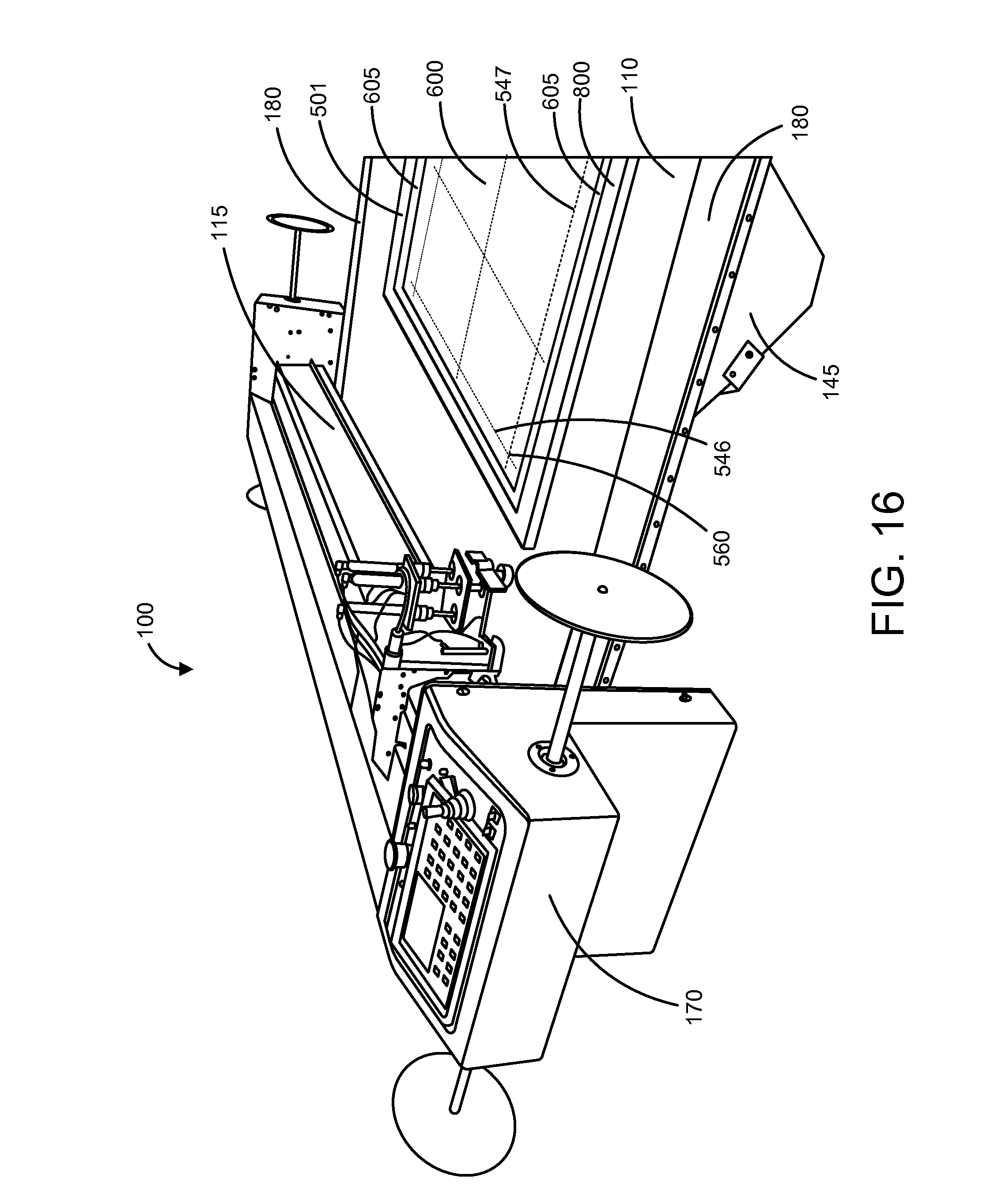
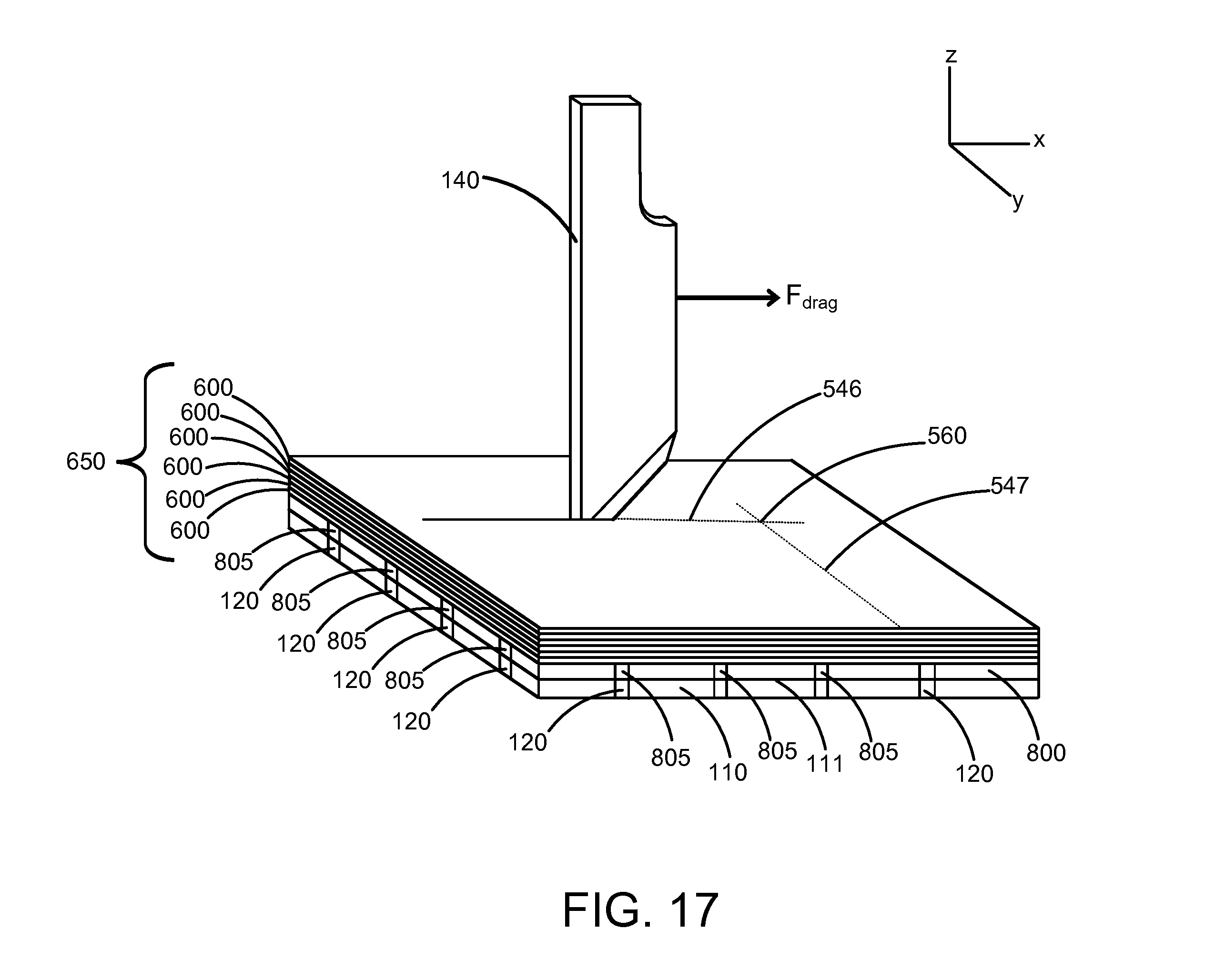
providing the cutting table comprising:
a top surface and a bottom surface opposite the top surface; a cutting tool movable relative to the top surface of the cutting table; a plurality of holes extending from the top surface to the bottom surface; a plenum in fluid communication with the bottom surface of the cutting table; a vacuum pump in fluid communication with the plenum, wherein the vacuum pump is adapted to produce a partial vacuum in the plenum while operating and draw air through the plurality of holes in the top surface of the cutting table; providing the stack of ballistic sheets to be cut, the stack of ballistic sheets comprising a first grouping of one or more ballistic sheets and a second grouping of one or more ballistic sheets, wherein the one or more ballistic sheets in the first grouping are more stiff than the one or more ballistic sheets in the second grouping of ballistic sheets, wherein the stack of ballistic sheets is arranged with the first grouping of ballistic sheets positioned on top of the second grouping of ballistic sheets; and providing a protective layer positioned on the top surface of the cutting table, the protective layer comprising:
a first surface and a second surface opposite the first surface, wherein the second surface of the protective layer is adapted to rest against a top surface of the cutting table, and wherein the first surface of the protective layer is adapted to receive and support the stack of ballistic sheets to be cut; and a plurality of air passages extending from the first surface of the protective layer to the second surface of the protective layer, wherein the plurality of air passages are adapted to permit airflow through the protective layer from the first surface of the protective layer to the second surface of the protective layer and into the plenum that is fluidly connected to the cutting table. 27. The method of 28. The method of 29. The method of 30. The method of performing a first cutting step along a first cutting pathway; and performing a second cutting step along a second cutting pathway, wherein the first cutting pathway and the second cutting pathway overlap, and wherein by performing the first cutting step and the second cutting step, a cleanly cut corner is produced in the stack of ballistic sheets proximate the overlap of the first and second cutting pathwaysCROSS-CITE TO RELATED APPLICATIONS
BACKGROUND
BRIEF DESCRIPTIONS OF DRAWINGS
DETAILED DESCRIPTION