INTEGRATED NIR AND VISIBLE LIGHT SCANNER FOR CO-REGISTERED IMAGES OF TISSUES
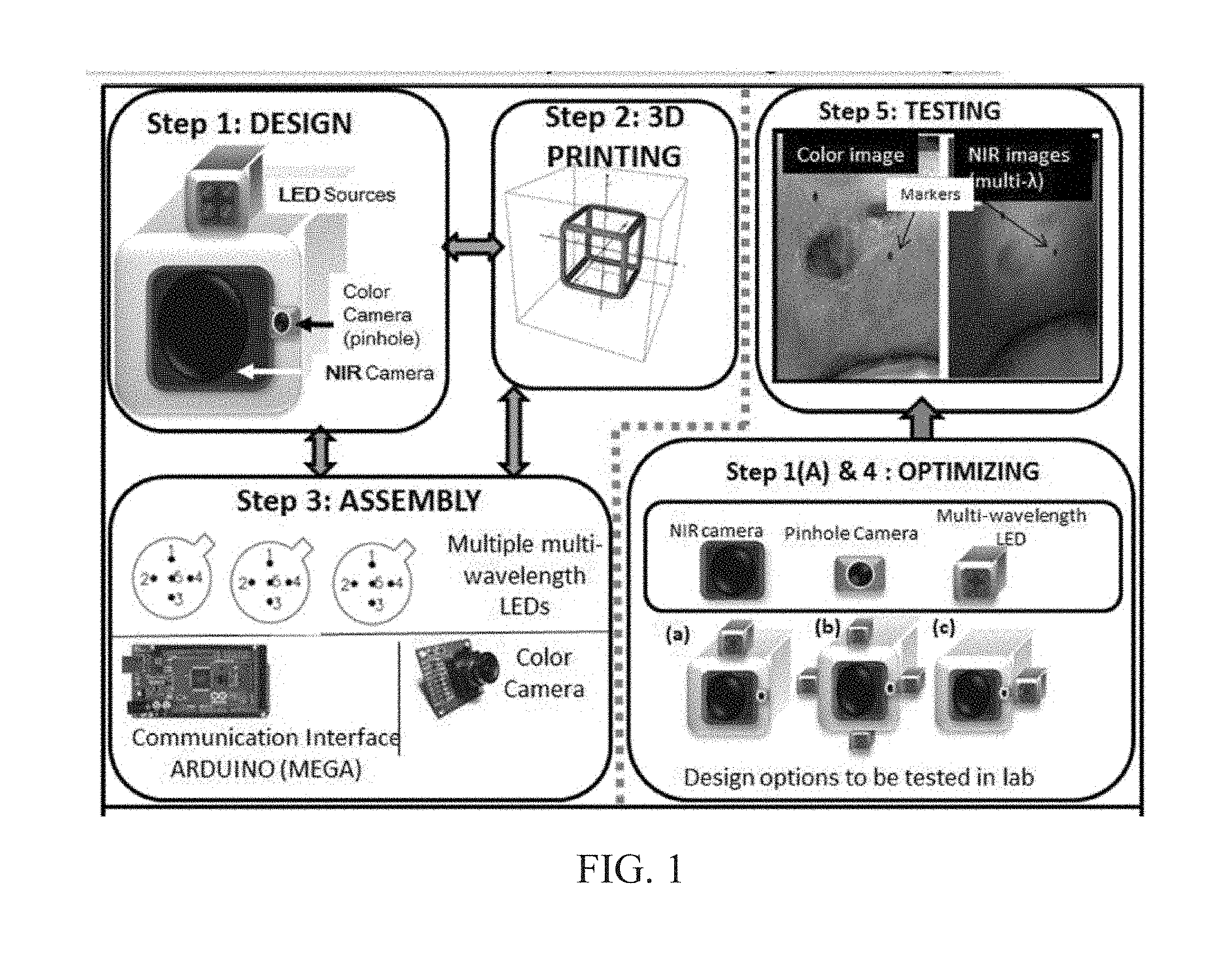
Chronic wounds affect approximately 6.5 million Americans and the incidence is expected to rise by 2% annually over the next decade, due to aging population, diabetes, obesity, and late effects of radiation therapy. Among the major chronic wounds are lower extremity ulcers (diabetic foot ulcers (DFUs) and venous leg ulcers (VLUs)), apart from pressure and arterial ulcers. The global wound care market is expected to reach $20.5 billion by 2020 at a cumulative annual growth rate of 8%, and just North America alone to $8.1 billion by 2020. Chronic wounds alone are responsible for over $7 billion/year in annual health care costs worldwide. The United States represents more than half the global market with lower extremity ulcers (DFUs and VLUs) being the most chronic wounds. Initial management of lower extremity ulcers begins with effective clinical assessment of the wound, diagnostic imaging using duplex ultrasound (to assess vascularity, or extent of blood flow), followed by basic and/or advanced treatments (or therapies) for enhancing effective and rapid wound healing. Healing rate is assessed by wound size measurement and visual assessment for surface epithelization. If treatment extends beyond 4 weeks, re-evaluation of wound and advanced treatment options are considered. While currently available diagnostic tools help direct the treatment approach and assess vascularity (i.e., oxygen-rich blood flow), there is no prognostic imaging tool in the clinic to assess improvement in blood oxygenation and simultaneously take spatial measurements of a target wound. Embodiments of the subject invention provide devices and methods for scanning near infrared (NIR) and visible light images of targeted wounds through non-invasive, non-contact, prognostic imaging tools that provide mapping changes in blood oxygenation of the wound region and obtaining wound size measurements. Embodiments of the subject invention provide non-contact and real-time NIR imaging of the entire wound region in less than or equal to one second of imaging time. Embodiments of the subject invention can use visible light capturing devices and NIR capturing devices to scan target tissues or wounds, obtain wound size measurements and/or measurements of chosen regions of interest, through automated wound or region of interest's boundary demarcation, and map blood oxygenation changes in small and large tissues or wounds to provide separate healing indicators in a single co-registered image. Embodiments of the subject invention provide systems and methods to create a co-registered image by overlaying a hemodynamic map onto a visible light image. In some embodiments, software can provide spatially co-registered hemodynamic and color images of a tissue, wound, region of interest and their peripheries, along with automated tissue, wound, or region of interest boundary demarcation and wound size measurement. Embodiments of the subject invention (at times referred to as the NIROScope) provide devices and methods for a prognostic optical imaging tool to monitor changes in blood flow of chronic wounds (e.g., lower extremity ulcers) and determine of wound size during the treatment process. It should be understood that the term “hemodynamic signals,” as used herein, can include or be used interchangeably with oxygenation parameter, blood oxygenation, tissue oxygenation, changes in oxy and deoxy hemoglobin or related parameters obtained from multi wavelength NIR data. It should be further understood that the term “visible light” can include visual light, white light, or digital color. Near infrared spectrometry (NIRS) is a vibration based spectrometry method that propagates electromagnetic waves within a range of 650 nm to 2500 nm and records the induced signal response. NIRS is advantageous when probing the human body as it is non-destructive, non-invasive, and fast with typical exposure time lasting less than a few minutes. Typical applications for NIRS include detecting neural activity, pulse oximetry, or analyzing biological tissue. Typical NIRS instruments vary based upon a desired application and wavelength selectivity, and typically fall into dispersive, filter, Fourier transform, LED, or Acousto-Optical Tunable Filter based instruments. Optical imaging modalities can image tissue functionality in terms of changes in blood flows (or oxygenation) and perfusion. Optical imaging devices can use light in the visible or near infrared light wavelengths to monitor changes in the blood flow in terms of oxy-(HbO), deoxyhemoglobin (HbR), oxygen saturation (StO2), total hemoglobin (HbT), and/or tissue perfusion of the wounds. Wounds undergo different stages of healing, including: inflammatory, proliferation, and remodeling. While healing wounds progress through all these stages towards complete closure, non-healing wounds remain at the inflammatory phase with stagnated blood (i.e. no blood flow or blood oxygenation). Hence, differences in blood oxygenation between wound and normal tissue, when optically imaged, can help determine the wound's responsiveness to the treatment process and progression towards healing. Embodiments of the subject invention can obtain wound size measurements (via automated or semi-automated wound boundary demarcations) and map blood oxygenation changes in small and large wounds (up to ˜8 cm in one dimension) to provide two healing indicators in a single co-registered image. Other embodiments of the subject invention can demarcate and measure the size of regions with changed blood-oxygenation in and around the wounds. Key advantages of embodiments of the subject invention include: (1) portability; (2) non-contact; (3) non-destructive; (4) ability to image small & large wounds (greater than 4 cm in a single dimension); (5) non-invasive (for example, no injection of contrast agents); (6) measurement of changes in blood oxygenation around wound (in terms of StO2, HbO, and HbR); and (7) operator independence for wound size measurements. Embodiments of the subject invention provide devices and methods for a non-invasive, non-contact, prognostic imaging tool to provide two healing indicators: (1) mapping changes in blood oxygenation of the wound region; and (2) obtaining wound size measurements. Embodiments of the subject invention provide non-contact and real-time NIR imaging of the entire wound region in less than or equal to one second of imaging time. The non-contact, non-radiative imaging makes the approach safe for use on subjects with infectious, non-infectious, painful, and/or sensitive wounds in comparison to a contact-based (using fibers) NIRS devices developed in the past. Additionally, embodiments of the subject invention can generate images of blood oxygenation of a wound of up to approximately 8 cm in one dimension in less than or equal to one second of imaging time. The imaging time of less than one second decreases the length of time of an overall prognostic assessment of healing in a routine outpatient clinical treatment. Embodiments of the subject invention provide at least two healing indicators in one device: (1) detection of changes in blood oxygenation and/or demarcating these regions; and (2) detection of changes in wound size. Changes in two dimensional hemodynamic concentrations maps (including but not limited to changes in terms of HbO, HbR, HbT, and StO2) of a wound can be detected. This can assist medical and research professionals in determining the contrast in oxygen rich blood flow into a wound, with respect to background or peripheries, and correlating these blood oxygenation changes across a specified treatment period. In addition, embodiments of the subject invention can also obtain wound size measurements, via automatic or semi-automated segmentation methods, with no operator dependability. In an embodiment, a portable hand-held device can be mobile to any clinical site or home care service. According to some embodiments, the device can be carried along with a laptop to any clinical site or home care service during weekly treatment and assessment of the wound. In some embodiments, the hand-held nature of the device allows it to flexibly image a wound from any location with ease and from a distance of more than 30 cm or 1 ft. from the wound, without having to move the patient. Embodiments of the subject invention can generate a spatially co-registered image, which includes both healing indicators in near-real time. The co-registered image can be created by overlaying a visible light or white light image upon a hemodynamic map or overlaying a hemodynamic map onto a visible light image. In some embodiments of the subject invention, software can provide spatially co-registered hemodynamic and color (i.e., visible light or white light) images of a wound and its peripheries, along with automated wound boundary demarcation and wound size. This can assist clinicians to correlate changes in blood oxygenation to wound size reduction across weeks of treatment from visual yet scaled co-registered images. In some embodiments of the subject invention, software can provide spatially co-registered demarcated boundaries of changed blood oxygenation (or hemodynamic maps) from a wound and its peripheries, along automated wound boundary demarcation (from visible light image) and wound size. This can assist clinicians to correlate changes in blood oxygenation to wound size reduction across weeks of treatment from quantitatively scaled, co-registered demarcated boundaries and sizes (as area). Embodiments of the subject invention can assess changes in blood flow (from hemodynamic wound maps) along with wound size measurements to potentially predict healing sooner than traditional benchmark approaches of measuring wound size; as physiological changes in the wound manifest prior to visually perceptible changes. In an embodiment, two healing indicators can be used to assess the effectiveness of the treatment approach and determine if oxygenation to the wound is impacted by a chosen treatment. By allowing clinicians to continue or alter chosen treatment plans even prior to the standard four week treatment plan (for each chosen treatment), reduction of the overall wound care costs is achieved. Embodiments of the subject invention (i.e., NIROScope) can comprise an image capturing device, an NIR image capturing device, a housing unit, in which the housing unit has at least one or more apertures to expose the image capturing device and the NIR image capturing device, a light source connected to the housing unit to illuminate a target region. An embodiment of the NIROScope can be seen in A process for fabricating a device according to an embodiment can comprise the following, as seen in A second step can be to fabricate the housing unit, including the appropriate location(s) of the light source, a visible light capturing device, including a digital color or white light image capturing device, and the NIR image capturing device into a single integrated device with 3D printing, in addition to an area to hold the source drivers. In certain embodiments, multiple multi-wavelength LEDs can be wired to a microcontroller via custom-designed and developed printed circuit boards (PCBs) and programmed. Multi-wavelength LEDs can be used due to HbO, HbR, HbT, and/or StO2change estimations requiring diffuse reflectance signals from 2 or more NIR wavelengths. Different image capturing devices can be implemented and selected based on resolution, size, color, FOV (to match with NIR-camera), and communication requirements. Embodiments of the subject invention can be integrated onto a hand-held body and wirelessly communicate with a computer readable medium (or via a USB, if wired). A NIR image capturing device along with appropriate optical filters and focusing lens can be assembled inside the hand-held body and communicate with the computer readable medium. Certain particular embodiments can be limited to a maximum size of 5×5×12 cm3and weigh less than 1 lb., including all the assembled components. A fourth step can be used to perform optimization to provide uniform illumination over large areas (at chosen NIR wavelengths) with stability over time. Parameters such as changes in source light intensity vs. time, and optimal distance from device to target vs. maximum area of illumination can be analyzed according to embodiments of the subject invention. An oscilloscope and optical power meter can be used to optimize the output wavelengths and intensity at each wavelength of the LED light source. This can allow uniform intensity of illumination across wavelengths during imaging. In certain embodiments of the subject invention, any remaining non-uniformity in illumination can be accounted for using diffusers and/or calibration approaches. Variation in source illumination strength, distance and angle of view of device from wound can be accounted for and optimized according to certain embodiments of the subject invention. Dark current noise and effect of ambient light can be estimated and accounted for during data analysis. The exposure time, focal length and resolution of NIR image capturing device can also be optimized to maximize the weak diffuse reflectance signals from the wounds. A fifth step can be to test the fabricated device by carrying out continuous-wave (CW) NIR imaging on tissue phantoms of homogenous optical properties, followed by in-vivo analysis on normal tissue, and on lower extremity ulcers. The testing can determine the maximum FOV of illumination and detection on simulated target regions (for example, 0.5-15 cm diameter) on tissue phantoms and normal tissue. Similarly, in certain embodiments of the subject invention, the FOV of the visible image capturing device and the NIR image capturing device can be configured for various distances of the device from the target (e.g. wound or tissue). A schematic of a potential flow for fabrication of the device is seen in A second module can comprise a patient portal and allow a user to interact with a subject's medical records. Through interaction with the widgets or graphical icons, a user can enter a subject's case history including test results, notes, and captured images. Additionally, a user can review previously entered data in order to evaluate a subject's progress. A third module can enable a user to engage image acquisition of the color and NIR images. A fourth module can comprise interactive tools for image processing including hemodynamic analysis, co-registration, and wound size analysis. The detected NIR light from two wavelengths can be used to determine changes (Δ) in HbO and HbR at every pixel of the NIR image using following formulas: in which L is a pathlength factor (calibrated), ε is a molar extinction coefficient of HbO or HbR at λ1or λ2(between 650 nm and 1000 nm), and ΔOD is a change in an optical density (which is additionally wavelength dependent). Additionally, in certain embodiments of the subject invention, dark noise and effect of ambient light can be accounted for during hemodynamic analysis. In certain embodiments, analysis of visible light images including digital color images, and oxygenation parameters can be achieved by leveraging image segmentation based algorithms. Image segmentation algorithms can use both contrast and texture information to perform automated or semi-automated segmentation. Segmentation techniques can include graph cuts, region growth, and/or other segmentation techniques used in general for image segmentation. A cut can be a partition that separates an image into two segments. Graph cut techniques can be a useful tool for accurately segmenting any type of image, which can result in a global solution since the technique is independent of the chosen initial center point. The algorithms can exploit similar gray values of closely situated pixels. After removing background noise, graph cut segmentation can reveal wound boundaries based on tissue oxygenation. Region growing is a region-based or pixel-based algorithm for image segmentation, a pixel-based technique in which initial seed points can be manually selected by the user. The difference between intensity value of a pixel and mean intensity value of the user-specified region can be computed to determine the similarity level between neighboring pixels and the new pixel, called maximum intensity distance. Therefore, this algorithm can leverage a human expert's knowledge through user input of seed locations for the wound, and outperform user independent algorithms that are purely dependent upon computer based detection of visual cues found on the images. In certain embodiments, two dimensional spatial maps of each oxygenation parameter (e.g., HbO, HbR, HbT, or any related parameter obtained from multi-wavelength NIR data) can be spatially co-registered onto visible light images, including digital color images of the wound or tissue of interest. Multi-map co-segmentation algorithms can be employed to differentiate healing vs. non-healing regions (for example, from demarcated wound boundaries and areas of changed blood flow, with or without demarcation). Spatial segmentation can facilitate demarcation of regions of interest and detection of their corresponding size changes during a treatment period, as seen in Hemodynamic analysis using 2 or 2 or more NIR wavelengths can be implemented using similar approach. Adding ΔHbO and ΔHbR gives ΔHbT (changes in total hemoglobin), and ΔHbO: ΔHbT estimates the StO2(saturated oxygen concentration). Second derivatives of either of the above parameters (i.e., ΔHbO, ΔHbR and/or ΔHbT) may also be estimated as part of hemodynamic analysis. Another feature of the fourth module can be interactive widgets or graphical icons that allow a user to implement spatial co-registration. The color and processed NIR images (i.e. hemodynamic maps) will be co-registered (overlaid) and can use reference markers for point selection in the transformation matrices. The differences in the visible light image capturing device and MR image capturing device's resolution can be accounted for via re-scaling the pixel areas through image processing techniques. The color and NIR images (at each imaged wavelength) can be co-registered for a visual comparison of a target (i.e., wound) size a n d hemodynamic maps, or the demarcated regions of changed oxygenation parameter(s), at and around the target during the imaging process. In another embodiment of the subject invention, the process flow can begin with (1) data acquisition, followed by (2) hemoanalysis imaging, and can be completed with (3) co-registration. Though systems and methods have been discussed with respect to wound care, embodiments are not limited thereto. Systems and methods of embodiments of the subject invention can be used for many other applications, including but not limited to pressure ulcers, diabetic foot ulcers, radiation-induced dermatitis for head/neck and breast cancer cases, and early cancer screening (e.g., breast cancer early screening). The methods and processes described herein can be embodied as code and/or data. The software code and data described herein can be stored on one or more machine-readable media (e.g., computer-readable media), which may include any device or medium that can store code and/or data for use by a computer system. When a computer system and/or processer reads and executes the code and/or data stored on a computer-readable medium, the computer system and/or processer performs the methods and processes embodied as data structures and code stored within the computer-readable storage medium. It should be appreciated by those skilled in the art that computer-readable media include removable and non-removable structures/devices that can be used for storage of information, such as computer-readable instructions, data structures, program modules, and other data used by a computing system/environment. A computer-readable medium includes, but is not limited to, volatile memory such as random access memories (RAM, DRAM, SRAM); and non-volatile memory such as flash memory, various read-only-memories (ROM, PROM, EPROM, EEPROM), magnetic and ferromagnetic/ferroelectric memories (MRAM, FeRAM), and magnetic and optical storage devices (hard drives, magnetic tape, CDs, DVDs); network devices; or other media now known or later developed that is capable of storing computer-readable information/data. Computer-readable media should not be construed or interpreted to include any propagating signals. A computer-readable medium of the subject invention can be, for example, a compact disc (CD), digital video disc (DVD), flash memory device, volatile memory, or a hard disk drive (HDD), such as an external HDD or the HDD of a computing device, though embodiments are not limited thereto. A computing device can be, for example, a laptop computer, desktop computer, server, cell phone, or tablet, though embodiments are not limited thereto. The subject invention includes, but is not limited to, the following exemplified embodiments. A system for scanning near infrared (NIR) and visible light images, the system comprising: an image capturing device configured to capture a visible light image (e.g., a visible light image comprising a digital color or white light image); an image capturing device configured to capture a near infrared (NIR) image; a portable, handheld housing unit configured to contain the visible light image capturing device and the NIR image capturing device; a light source configured to illuminate a target area and in operable communication with (e.g., connected to) the housing unit; a plurality of drivers configured to control the light source; a processor; and a machine-readable medium comprising machine-executable instructions stored thereon, in operable communication with the processor. The system of embodiment 1, in which the processor is configured to generate a near real time hemodynamic signal, and in which the processor is configured to detect a dimensional measurements of a target tissue wound. The system of any of embodiments 1-2, in which the visible image capturing device and the NIR image capturing device are configured to capture the same or similar field of view. The system of any of embodiments 1-3, in which the system is configured to use light in the visible or near infrared light wavelengths to monitor changes in the blood flow in terms of oxy- (HbO), deoxyhemoglobin (HbR), oxygen saturation (StO2), total hemoglobin (HbT), other derived oxygenation parameters, and/or tissue perfusion of the wounds Or tissue of interest. The system according to any of embodiments 1-4, in which the system can detect MR light from at least two wavelengths to determine changes (A) in HbO and HbR at every pixel of the NIR image using following formulas: where L is a pathlength factor (calibrated), ε is a molar extinction coefficient of HbO or HbR at λ1or λ2(between 650 nm and 1000 nm), and ΔOD is a change in an optical density (which is additionally wavelength dependent). The system of any of embodiments 1-5, in which the light source is configured to emit light of at least one wavelength. The system of any of the embodiments 1-6, in which the light source is configured to emit light at a first wavelength and sequentially or simultaneously to light at a second wavelength. The system of any of embodiments 1-7, in which the NIR image capturing device is configured to capture the NIR image of at least two different wavelengths. The system of any of embodiments 1-8, in which the processor is configured to detect and differentiate MR images of at least two wavelengths. The system of any of embodiments 1-9, in which the processor is configured to detect a diffuse reflectance signal from at least 2 NIR wavelengths and generate a hemodynamic signal. The system of any of embodiments 1-10, in which the processor is configured to capture a plurality of visible light images (for example, digital color or white light images) in the form of static images or a video. The system of any of embodiments 1-11, in which the processor is configured to capture a plurality of NIR images in the form of a static images or a video. The system of any of embodiments 1-12, in which the processor is configured to capture the NIR images, capture the visible light images, generate hemodynamic maps, overlay or co-register a hemodynamic map (for example, a HbO, HbR, or HbT map) onto the visible light images, including a digital color or white light image, to form a static single image. The system of embodiments 1-13, in which the pressor is configured to capture an NIR image overlay or co-register the NIR image onto a visible light image. The system of any of embodiments 1-14 in which the processor is configured to capture the MR images, capture the visible light images, generate hemodynamic maps, analyze tissue or wound measurements using image segmentation algorithms, generate a spatially co-registered image. The system of any of embodiments 1-15, in which the processor is configured to capture a plurality of NIR images, capture a plurality of visible light images, including digital color or white light images, and overlay the images to generate a single video. The system of any of embodiments 1-16, in which the processor is configured to capture a plurality of NIR images, capture a plurality of visible light images, including digital color or white light images, and analyze tissue or wound images using image segmentation algorithms, and generate spatially co-registered images in the form of a video. The system of any of embodiments 1-19, in which the system further comprises a graphical user interface (GUI). The system of embodiment 18, in which the GUI comprises a plurality of modules, in which the modules permit a user to interact with the system to perform tasks, in which the task comprise: initialization of the system, access to a patient's medical information, data acquisition, image processing, hemodynamic analysis, co-registration, and adjusting general camera settings. The system of any of embodiments 1-19, further comprising wireless circuitry (for example, Bluetooth), such that the visible image capturing device, the NIR image capturing device and light source can wirelessly communicate with the processor and the machine readable medium. The system of any of embodiments 1-20, in which the processor is configured to capture a single visible light image and provide a real time image in the form of a static image or a video. The system of any of embodiments 1-21, in which the processor is configured to capture a single NIR image and provide a near real time image in the form of a static image or a video. The system of any of embodiments 1-22, in which the processor is configured to remove a selected portion of the visible light image(s). The system of any of embodiments 1-23, in which the processor is configured to remove a selected portion of the NIR image(s). The system of any of embodiments 1-24, in which the processor is configured to detect and remove a noise signal and an effect of ambient light during image analysis. The system of any of embodiments 1-25, in which the processor is configured to monitor the changes in the blood flow in terms of oxy- (HbO), deoxyhemoglobin (HbR), oxygen saturation (StO2), total hemoglobin (HbT), other derived oxygenation parameters (i.e. second derivatives) and/or tissue perfusion of the wounds. The system of any of embodiments 1-26, in which the processor is configured to monitor changes in the measurement of a target tissue. A device for scanning near infrared (NIR) and visible light images, the device comprising: an image capturing device configured to capture a visible light image (e.g., a visible light image comprising a digital color or white light image); an image capturing device configured to capture a near infrared red (NIR) image at a plurality of wavelengths; a portable, handheld housing unit configured to contain the visible light image capturing device and the NIR image capturing device, in which the portable handheld housing unit comprises a front face, a right side face, and left side face, a back face, a top face and a bottom face, in which the visible light image capturing device and the NIR image capturing device are configured to capture the same or similar point of view; a mounting clip connected to the housing unit on the bottom face and near the back face; a light source to illuminate a target tissue and connected to the housing unit; a processor; and a machine-readable medium comprising machine-executable instructions stored thereon, in operable communication with the processor. The device of embodiment 28, in which light source is configured emit light of at least one wavelength. The device of any of embodiment 28-29, in which the processor is configured to generate a near real time hemodynamic signal. The device of any of embodiment 28-30, in which the processor is further configured to detect light of at least one wavelength. The device of any of embodiment 28-31, in which the processor is configured to use image segmentation techniques to execute a size measurement of a target tissue. The device of any of embodiment 28-32, in which the light source is connected to the top face of the housing unit and is near the front face. The device of any of embodiment 28-33, in which the light source is connected by a hinge to the top face of a housing unit and is near the front face. A method scanning near infrared (NIR) and visible light images, the method comprising: placing the device of any of embodiments 28-34 at a distance from a target tissue; configuring the visible light image capturing device and the NIR image capturing device to have a same field of view onto the target tissue; illuminating the target wound, with the light source, with at least one wavelength; capturing a visible light image (e.g., a visible light image comprising a digital color or white light image) and an NIR image, of at least one wavelength, of the target tissue. The method according to embodiment 35, in which the method further comprises detecting a NIR signal from each wavelength emitted from the light source; detecting a noise signal; selecting an unwanted region of the visible light image of the target wound; processing the visible light image and the NIR image to remove the unwanted regions and to remove the noise signal; producing a hemodynamic map; and processing the visible light image to determine size of wound. The method according to any of embodiments 35-36, in which the method further comprises selecting corresponding marker points on the NIR image and the visible light image; generate a transformational mapping matrix based upon the selected points; and overlaying the NIR image, hemodynamic map, or segmented boundaries of NIR image or hemodynamic map onto the visible light image to produce a single image. The method according to any of embodiments 35-37, in which the method further comprises selecting corresponding marker points on the NIR image and the visible light image; generate a transformational mapping matrix based upon the selected points; and using image segmentation techniques to overlay the NIR image, the hemodynamic map, and/or segmented boundaries of NIR image or hemodynamic map onto the visible light image to produce a single image. The method according to any of embodiments 35-38, in which the method comprises capturing a plurality of the visible light images and a plurality the NIR images, and overlaying or co-registering the plurality of visible light and NIR images to produce and display a single video. A greater understanding of the present invention and of its many advantages may be had from the following example, given by way of illustration. The following example is illustrative of some of the methods, applications, embodiments and variants of the present invention. The example is, of course, not to be considered as limiting the invention. Numerous changes and modifications can be made with respect to the invention. Use of two cameras in a lab setting (endoscopic for color image and CMOS camera for MR images) co-registered the color and NIR images with 70% accuracy, while involving 1 minute in positioning the endoscopic camera for similar orientation and FOV as the NIR-camera. A preliminary test using an integrated pinhole color camera onto the hand-held body of NIR camera co-registered the two images with over 80% accuracy, while involving no additional time in positioning the pinhole camera, as see in It should be understood that the examples and embodiments described herein are for illustrative purposes only and that various modifications or changes in light thereof will be suggested to persons skilled in the art and are to be included within the spirit and purview of this application. All patents, patent applications, provisional applications, and publications referred to or cited herein (including those in the “References” section) are incorporated by reference in their entirety, including all figures and tables, to the extent they are not inconsistent with the explicit teachings of this specification. Systems and methods for scanning near infrared (NIR) and visible light images and creating co-registered images are provided. A system can include a visible light image capturing device, an near infrared image capturing device, a housing unit, a light source configured to emit light at multiple wavelengths, and a processor configured to use image segmentation algorithms to measure a target issue or wound, detect hemodynamic signals, and combine the visible light image and a hemodynamic image to create a single image. 1. A system for scanning near infrared (NIR) and visible light images. the system comprising:
a visible image capturing device configured to capture a visible light image, the visible light image comprising a digital color or white light image; a near infrared image capturing device configured to capture a near infrared (NIR) image of at least one wavelength; a portable, handheld, housing unit configured to contain the visible image capturing device and the NIR image capturing device; a light source configured to illuminate a target area and connected to the housing unit, a plurality of drivers configured to control the light source; a processor; and a machine-readable medium comprising machine-executable instructions stored thereon, in operable communication with the processor, the light source comprising a plurality of light emitting diodes (LEDs) configured to emit light waves of at least one wavelength, the processor being configured to detect at least one NIR signal at at least one wavelength and generate a hemodynamic signal, the processor being configured to detect dimensional measurements of a target tissue or wound, the NIR image capturing device being disposed on a front face of the housing unit, and the light source being disposed on a top face of the housing unit through a hinge, such that an angle of illumination provided by the light source is adjustable via the hinge without moving the housing unit. 2. The system of 3. The system of 4. The system of where L is a pathlength factor, ε is a molar extinction coefficient of HbO or HbR at λ1or λ2between 650 nm and 1000 nm, and ΔOD is a change in an optical density. 5. The system of 6. The system of 7. The system of 8. The system of 9. The system of 10. The system of 11. The system of 12. The system of 13. The system of 14. The system of 15. A device for scanning near infrared (NIR) and visible light images, the device comprising:
a visible image capturing device configured to capture a visible light image, the visible light image comprising a digital color or white light image; a near infrared (NIR) image capturing device configured to capture an NIR image of at least one wavelength; a portable, handheld housing unit configured to contain the visible light image capturing device and the NIR image capturing device, the portable handheld housing unit comprising a front face, a right side face, a left side face, a back face, a top face, and a bottom face, and the visible light image capturing device and the NIR image capturing device being configured to capture the same or similar point of view; a mounting clip connected to the housing unit on the bottom face and near the back face; a light source configured to illuminate a target area and connected to the housing unit; a processor; and a machine-readable medium comprising machine-executable instructions stored thereon, in operable communication with the processor, the light source being disposed on the top face of the housing unit and being near the front face; the processor being configured to detect an NIR signal and generate a hemodynamic signal, the processor being further configured to detect at least one wavelength, the processor being configured to execute dimensional measurements of a target tissue or wound, the NIR image capturing device being disposed on the front face of the housing unit, and the light source being disposed on the top face of the housing unit through a hinge, such that an angle of illumination provided by the light source is adjustable via the hinge without moving the housing unit. 16. A method of scanning near infrared (NIR) and visible light images, the method comprising:
placing the device of configuring the visible light image capturing device and the NIR image capturing device to have a same field of view onto the target tissue; illuminating the target wound, with the light source of at least one wavelength; capturing at least one visible light image and at least one NIR image of the target tissue; detecting an NIR signal from each wavelength emitted from the light source; detecting a noise signal; selecting an unwanted region of the visible light image of the target tissue; processing the visible light image and the NIR image to remove the unwanted region and to remove the noise signal; generating a hemodynamic map; detecting a size measurement of the target tissue or wound; selecting corresponding marker points on the NIR image and the visible light image; generating a transformational mapping matrix based upon the selected points; and co-registering the hemodynamic map onto the visible light image based upon the transformational matrix to produce a single image. 17. The method to of 18. The method of the processor being further configured to further co-register the demarcated boundaries obtained from the NIR image onto the visible light image. 19. The method according to 20. The method according to BACKGROUND
BRIEF SUMMARY
BRIEF DESCRIPTION OF DRAWINGS
DETAILED DESCRIPTION
Embodiment 1
Embodiment 2
Embodiment 3
Embodiment 4
Embodiment 5
Embodiment 6
Embodiment 7
Embodiment 8
Embodiment 9
Embodiment 10
Embodiment 11
Embodiment 12
Embodiment 13
Embodiment 14
Embodiment 15
Embodiment 16
Embodiment 17
Embodiment 18
Embodiment 19
Embodiment 20
Embodiment 21
Embodiment 22
Embodiment 23
Embodiment 24
Embodiment 25
Embodiment 26
Embodiment 27
Embodiment 28
Embodiment 29
Embodiment 30
Embodiment 31
Embodiment 32
Embodiment 33
Embodiment 34
Embodiment 35
Embodiment 36
Embodiment 37
Embodiment 38
Embodiment 39
Example 1
REFERENCES