구동 트레인 및 섀시
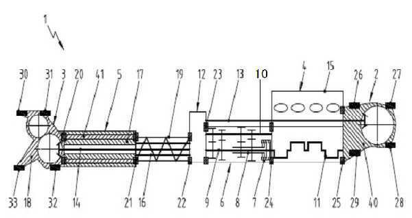
The present invention refers to in particular hybrid vehicle driving train and chassis are disclosed. The present invention and the present invention can be applied to all motor vehicles based on door number point criterion with respect to a vehicle but described more specifically. Generally, a plurality of hybrid vehicle drive assembly, e.g. a vehicle drive train having an internal combustion engine machine big. To obtain highly energy efficiency, hybrid vehicle electric machine provided with a conventional internal combustion engine to enable selective delivery of the way torque transmission way additional parallel hybrid drive is measured for plural times. For example, startup and acceleration process typically occurs frequently in traffic produces in a hybrid vehicle are preferably performed by the aid or to an electric machine, an internal combustion engine varies the load frequently operable fuel consumption and since there is an increase in soil release are disclosed. In contrast to an internal combustion engine, the electric machine is low even internal combustion engine rotation speed, has an effect on high torque from substantially stationary, in particular suitable for starting and acceleration process. On the contrary, an internal combustion engine is only its nominal rotational speed, e.g. constant speed traveling can be only operate at a high efficiency. To combine the benefits of electric machine advantages and of an internal combustion engine, power of an internal combustion engine and of the electric machine drive system both power supply drive system in such a way as structurally configure the spirit. Disclosure Official Gazette DE 602 19 898 T 2, US 6,881,168 B2, US 6,533,692 B1 main transmission for hybrid vehicle that is fastened to each of the internal combustion engine drive train power distribution through disclosure as follows. The electric power dispenser integrated with each other. In each case, front and rear power divider output shaft in front of and behind each front and rear axle differential driving substrate. Power splitter for an internal combustion engine of hybrid vehicle front and/or rear axle for dynamo electric machine power and/or power can be delivered. However, this structure, front and rear axle for dynamo electric machine high torque must be delivered virtually due to integration, power distribution in response to the comparison weight and installation space can be implemented only by realizing adaptation having been made. In addition, the aforementioned structure in addition self-supporting (self-a supporting) inner portion of absorbent structures, a drive train chassis receiving high weight, having inherent stiffness corresponding designed to accomplishing. Thus, the purpose of the invention these points a stand-alone number number under public affairs improved a drive train 30 to 60 seconds. According to the present invention, said object is achieved according to Claim 1 drive train and/or the claims claims features according to Claim 10 chassis is achieved by features. According to the present invention, in particular as for hybrid vehicle drive train, axle transmission number 1, number 2 axle transmission, and/or number 2 acting on the internal combustion engine can be connected to axle transmission number 1, number 2 and number 1 and/or include an electric machine can be connected to and acting on the axle transmission, axle transmission number 1, internal combustion engine, electric machine, and a drive train axle transmission number 2 is configured in such a way that are interlinked by self-supporting structure, co number encoded drive train. In addition, in particular as for hybrid vehicle chassis, said types of drive train, acting on the rear axle connected axle transmission number 1, number 2 and acting on a front axle connected axle transmission which, acting mechanical load force is greater than the welding of the chassis can be another train such that the drive axle input shaft, ball chassis number is encoded. The basic general outline of the present invention, driving train onto a self-supporting manner more mechanical load a drive train, the drive train of drive assembly interconnected by designing or hypermetropia. As a result, drive train about load support is formed, as a result, for example, reduced weight and reduced drive train connected to the vehicle body rigidity can be implementing. Thus, the preform according to the aforementioned prior art, the present invention refers to achieve weight saving form suitable for delivery keeps the drive train has a advantage of integrated. Preferred embodiment embodiment dependent on claims number 1 anti specified in the drive train of anti to being described. According to a preferred embodiment, an internal combustion engine is arranged between the axle transmission and electric machine number 1, number 2 between axle transmission comprising an internal combustion engine electric machine disposed thereon. A drive train in an automobile engine is advantageously disposed intermediate the use nephrophathy. According to another preferred embodiment, drive train comprises, means to selectively drive the output shaft and the axle transmission number 1 number 1, number 2 number 2 selectively driving axle transmission output shaft which comprises an internal combustion engine machine that is located between the power distributor. Power splitter for an internal combustion engine in order to distribute power and/or axle transmission power of an electric machine capable of number 1 and number 2, as a result number it became [e[e] wheel slip is embodied. In another preferred according to one aspect, drive train comprises, power distributor internal combustion engine power units are arranged between the main gearbox and interacts dispenser, electric machine powered by electric machine output shaft interacts dispenser can be. To the power output of an internal combustion engine by main transmission ratio desired for hereinafter can be shifted disclosed. According to one aspect preferably, drive train comprises power distributor electric machine that is located between the spacer structure, in particular by means of the adjustable load bearing. Thereby various vehicle drive train can be compliant to hereinafter for various wheel base, used in the drive train of the extends the range with each other. According to another preferred embodiment, axle transmission number 1, number 2 axle transmission, internal combustion engine and/or electric machine and/or power distributor and/or near transmission and/or spacer structure, axle transmission number 1, number 2 axle transmission, internal combustion engine and/or electric machine and/or power distributor and/or near one of the axle transmission axle transmission and/or spacer structure transmission and method for interconnecting another axle transmission connection means designed the mechanical scraper. As a result, the drive train of driving elements, one of the axle transmission axle transmission are loaded another axle transmission designed to propagate a manner, hereinafter for reliably connecting the process from each other. According to another preferred improvement, body and/or chassis of a vehicle drive train which is designed for mounting drive train comprising the support points and/or joint point. The elasticity of the drive train of vehicle chassis and/or body is substantially use nephrophathy. Thus, chassis and/or body can be reduced stiffness and reduced weight design. According to another preferred improvement, the electric machine is number 2 axle transmission axle placed inside a transmission housing. The electric machine drive train nephrophathy integrating a space-saving manner. According to another preferred embodiment, the internal combustion engine and/or electrical machine axle transmission from power distribution can be designed in such a way number and combination, an internal combustion engine and the electric power distributor acted upon by main transmission can be connected. This e.g. energy store charge generator electric machine for operating an internal combustion engine machine purposes directly to the HL2. With reference to the appended drawing of the present invention in the embodiment hereinafter described needed. Figure 1 shows a preferred embodiment according to the drive train of a side of the present invention also are disclosed. Figure 2 shows a preferred embodiment according to said type of a drive train of the present invention also a plane of the chassis are disclosed. In appended drawing, not with the same drawing code described exhibits similar or functionally same components. Figure 1 shows a preferred embodiment according to the also of the present invention, in particular in the drive train of side for hybrid vehicle are disclosed. The drive train (1) is preferably number 1 axle transmission (2), number 2 axle transmission (3), number 1 axle transmission (2) on axle transmission number 2 (3) that is located between the internal combustion engine (4), and internal combustion engine (4) and number 2 axle transmission (3) that is located between the electric machine (5) having a predetermined wavelength. Internal combustion engine (4) for example combustion engine (4), in particular gasoline engine (4) are designed. Number 1 axle transmission (2) is further provided for e.g. an automotive rear axle of driving a gearbox housing (40) with the rear axle transmission (2) and designed, number 2 axle transmission (3) is further provided with a front axle of a gearbox housing for driving for example motorcars (18) provided which comprises a front axle transmission (3) are designed as substrate. The axle transmission (2, 3) the gear transmission ratio is preferably, axle transmission are (2, 3) is to operate the low torque and high rotational speed and in such a way as, and forward axle and the rear axle for driving the axle transmission (2, 3) by the ratio of the corresponding axle transmission (2, 3) high torque is generated in a manner that lines are deleted. Electric machine (5) preferably has a e.g. hollow shaft (16) are designed as electric machine output shaft (16), a tubular stator (41), and a stator (41) rotating inside the, similarly tubular rotor (17) having a predetermined wavelength. Rotor (17) preferably has a electric machine output shaft (16) acting on the connected thereto. Electric machine (5) is further provided for example number 2 axle transmission (3) of a gearbox housing (18) placed inside a. Preferably, electric machine (5) is a gearbox housing (18) integrated with each other. I.e., weight reduction gearbox housing (18) the electric motor (5) housing formed on the substrate. Electric machine (5) preferably has a selectively the generator can be operated electric motor. Electric machine (5) is further provided (not shown) for example energy store electrically connected thereto. Electric machine (5) an electric motor taking energy when operated energy store, when operated energy store supplied energy to the generator. In addition, the drive train (1) is, for example, an internal combustion engine (4) are allocated to the electric machine (5) internal combustion engine (4) between a main transmission (6) having a predetermined wavelength. Main transmission (6) is further provided example passive transmission, automatic transmission, double clutch transmission, or continuously variable transmission are designed as substrate. Main transmission (6) preferably has a gear using an integrator, in particular a plurality of forward gear and one reverse gear stage with each other. Main transmission (6) e.g. in Figure 1 has a double clutch transmission (7), number 1 input shaft (8), number 2 input shaft (9) and a main shaft (10) with a double clutch transmission (6) shown diagrammatically in the nanometer range. Number 1 or number 2 input shaft (8, 9) is a double clutch (7) produces an internal combustion engine (4) crankshaft (11) can be interacts selectively. Main transmission (6) of the main shaft (10) number 1 or number 2 on input shaft (8, 9) by selecting a corresponding ratio between the main transmission (6) can be selecting a desired ratio. The drive train (1) for example electric machine (5) please come transmission (6) that is located between the distributor (12) having a predetermined wavelength. A distributor (12) includes a number 1 axle transmission (2) number 1 to selectively drive the output shaft (13) on axle transmission number 2 (3) the number 2 to selectively drive the output shaft (14) contact with each other. A distributor (12) includes a number 1 output shaft (13) and/or number 2 output shaft (14) and drives the or two shaft (13, 14) to be rotated either shaft suitable disclosed. Number 1 output shaft (13) is e.g. an internal combustion engine (4) extending through. Preferably, number 1 output shaft (13) internal combustion engine (4) housing (15) through the top of the axle transmission number 1 (2) extending into. A distributor (12) number 2 of output shaft (14) preferably has a hollow shaft (16) are designed as an electric machine output shaft (16) of the electrical machine (5), in particular electric machine (5) rotor (17) number 2 through the axle transmission (3) extending into. Internal combustion engine (4) for example main transmission (6) or near transmission (6) of the main shaft (10) by a distributor (12) interacts to can be. Electric machine (5) in an electric machine output shaft (16) by a distributor (12) interacts to can be. The axle transmission (2, 3) their transmission ratio therefore with high speed low input torque for applying, a distributor (12) output shafts (13, 14) and small as possible cross-section can be selected, the output shafts (13, 14) and weight and drive train according to (1) weight reduction is achieved. Internal combustion engine (4) the number 1 axle transmission (2) and/or number 2 axle transmission (3) in order to drive a main transmission (6) to a distributor (12) number 1 by axle transmission (2) and/or number 2 axle transmission (3) can be interacts to. Electric machine (5) in an electric machine output shaft (16) to a distributor (12) by similarly number 1 axle transmission (2) and/or number 2 axle transmission (3) can be interacts to. Number 1 axle transmission (2) and/or number 2 axle transmission (3) to an internal combustion engine (4) and/or have electric machine (5) of driving force distribution, e.g. a distributor as a function of the current tire slip in the drive tire (12) desired by a can be set as desired. Thus, the drive train (1) for driving the clutch collar and drive it became [e[e] number can be used. In addition, an internal combustion engine (4) and electric machine (5) both a distributor (12) are by axle transmission (2, 3) can be number combination from, the driving torque are axle transmission (2, 3) do not transfer to the. A distributor (12) by electric machine (5) is provided to raise the transmission (6), number 2 axle transmission (3), internal combustion engine (4), or number 1 axle transmission (2) are allocated to the or, or distributor (12) by moving assignment can be overlapping. Electric machine (5) in an electric machine output shaft (16), a distributor (12), and a main transmission (6) produces an internal combustion engine (4) crankshaft (11) can be coupled directly to the. Electric machine (5) internal combustion engine (4) coupled directly by, for example, are torque for an axle transmission (2, 3) without delivering, internal combustion engine (4) a generator operated electric machine (5) is more than by charging the energy store. On the other hand, electric machine (5) internal combustion engine (4) can be used for starting. In addition, the drive train (1) the types of drive train (1) of a vehicle as positioned at the aforementioned high dynamic traveling along, e.g. an automotive tire has the maximum transverse force delivery but cannot propagate in longitudinal direction power engine (4) cannot be used to propel the vehicle in the peaks of examples of power, internal combustion engine (4) the drive to a distributor (12) please come transmission (6) through electric machine (5) can be transferred onto the charging energy store. Next, after translation of the curve is the stored energy is the car from an electric machine (5) by curve of the accelerator can be used. Therefore, the charging apex such as publicly known internal combustion engine (4) using nephrophathy increase of rate over time. For example, preferably electric machine output shaft (16) surrounding the load bearing spacer structure (19) the power distributor (12) of the electrical machine (5) disposed thereon between. Spacer structure (19) is preferably load bearing lattice structure (19) are designed as substrate. Spacer structure (19) for example, types of said drive train (1) for a motor vehicle axle transmission are (2, 3) are used adapting axle base due to wheel base. Number 1 axle transmission (2), an internal combustion engine (4), main transmission (6), a distributor (12), spacer structure (19), an electric machine (5), and/or number 2 axle transmission (3) preferably has a drive train (1) the self-supporting structure in such a way as connected each other. I.e., drive train (1) acting on the mechanical load, e.g. torsion moment since the bending moment and/or internal combustion engine (4), an electric machine (5), main transmission (6), a distributor (12), and/or spacer structure (19) are by axle transmission (2, 3) another one of the axle transmission axle transmission (2, 3) can be delivered. For this purpose, axle transmission number 1 (2), number 2 axle transmission (3), internal combustion engine (4), an electric machine (5), a distributor (12), main transmission (6), and/or spacer structure (19) is, e.g. number 1 axle transmission (2), number 2 axle transmission (3), internal combustion engine (4), an electric machine (5), a distributor (12), main transmission (6), and/or spacer structure (19) which serves to connect the connection means (20 - 25) comprises. At this time, connection means (20 - 25) in each case the drive train (1) mechanical load acting on the drive train (1) parts (2 - 6, 12, and/or 19) disposed adjacent from component (2 - 6, 12, and/or 19) of the ms.. For example torsion moment and/or bending moment acting mechanical load are disclosed. The first attachment means (20 - 25) for example adhesion joint, weld joint, screw connection, plug connection, and/or riveted joint comprises. In addition, components (2 - 6, 12, and/or 19) having the reinforcing rib or grille structure such as for example an increase in weight minimization value λ2 optimization of the flow of force. In addition, in order to improve the rigidity and intrinsic stability, drive train (1) comprising a reinforcing board and/or carrier such as reinforcement can be. Thus, the drive train (1) is self-supporting structure results in the axle transmission (2, 3), internal combustion engine (4), main transmission (6), and/or electric machine (5) as well as accommodate a drive assembly such as may be, secondary frame load bearing function can be a vehicle body or chassis. As a result, for example, lightweight vehicle body having a low stiffness requirements further process from use. In addition, the drive train (1) is preferably a drive train of vehicle body and/or chassis (1) which is designed for mounting support points and/or joint points (26 - 33) comprises. Preferably, support points and/or joint points (26 - 33) is number 1 axle transmission (2) and/or number 2 axle transmission (3) on the pair of substrates. Support points and/or joint points (26 - 33) connecting points for example screw, rivet points and/or welding spots with each other. Figure 2 shows a preferred embodiment according to said type of a drive train of the present invention also a plane of the chassis are disclosed. The drive train (1) application of vehicle, in particular for hybrid vehicle chassis (34) are completed. Chassis (34) a drive train (1), and number 1 axle transmission (2) interacts to vehicle rear axle (35) with each other. A front axle (36) is number 2 axle transmission (3) acting on the connected thereto. The axle (35, 36) each in the form of for example independent wheel suspension device both 61. In addition, chassis (34) are rear and front wheel suspension device is e.g. (37, 38, 39, 42) comprises. For example, tires (43 - 46) are wheel suspension device (37, 38, 39, 42) are mounted. In addition, chassis (34) is further provided can be for example chassis auxiliary frame. Support points and/or joint points (26 - 33) for example chassis (34) auxiliary frame or chassis drive train (1) to be mounted on a disposed thereon. The drive train (1) is formed on the self-supporting structure substantially chassis (34) equal to the elasticity of the 4. Therefore, chassis (34) the mechanical load acting on the drive train (1) by, are two axle (35, 36) are one of two axle axle from (35, 36) can be another one of the input shaft. The, drive train (1) highly integrated reduced weight using such structure is more than. In this case, the drive train (1) is preferably a structure of a center tunnel in form a tubular structure. As a result, e.g., two or more rigid requirements and reduced-weight according to a vehicle chassis can be auxiliary frames. The drive train (1) has two axles (2,3), where an internal combustion engine (4) is operatively connected with the two axles. An electric motor (5) is operatively connected with the two axles. The former axle is designed with the internal combustion engine, electric motor and the latter axle, such that the drive train forms a self-supporting arrangement. An independent claim is also included for a chassis, particularly for a hybrid motor vehicle. Number 1 axle transmission (2) on, number 2 axle transmission (3) on, number 1 axle transmission (2), axle transmission number 2 (3) or number 1 and number 2 are axle transmission (2, 3) can be connected to act on the internal combustion engine (4) and, axle transmission number 1 (2), axle transmission number 2 (3) or number 1 and number 2 are axle transmission (2, 3) can be connected to act on the electric machine (5) with a drive train (1) as, number 1 axle transmission (2), an internal combustion engine (4), an electric machine (5), and number 2 axle transmission (3) is, in the drive train (1) the self-supporting structure and configured in such a way to each other, an internal combustion engine (4) and electrical machine (5) is number 1 axle transmission (2) on axle transmission number 2 (3) arranged between the, internal combustion engine (4) one end of the axle transmission number 1 (2) or number 2 axle transmission (3) connected to the, internal combustion engine (4) other end of the extension electric machine (5) connected to the, electric machine (5) one end of the axle transmission number 1 (2) or number 2 axle transmission (3) is connected, electric machine (5) other end of the extension internal combustion engine (4) is connected to, drive train (1) mechanical load acting on the axle transmission number 1 (2) from an internal combustion engine (4) and electrical machine (5) via a number 2 axle transmission (3) which also can be delivered, drive train. According to Claim 1, an internal combustion engine (4) is number 1 axle transmission (2) of the electrical machine (5) arranged between the, electric machine (5) internal combustion engine (4) and number 2 axle transmission (3) being disposed between characterized, drive train. According to Claim 1 or Claim 2, drive train (1) is, axle transmission number 1 (2) the number 1 means to selectively drive the output shaft (13) on, axle transmission number 2 (3) the number 2 to selectively drive the output shaft (14) having an internal combustion engine (4) and electric machine (5) that is located between the distributor (12) including a characterized the, drive train. According to Claim 3, drive train (1) is, a distributor (12) internal combustion engine (4) are arranged between the distributor (12) interacts to main transmission (6) and, electric machine (5) in an electric machine output shaft (16) by a distributor (12) can be interacts to characterized, drive train. According to Claim 3, drive train (1) is a distributor (12) of the electrical machine (5) that is located between the load bearing spacer structure (19) including a characterized the, drive train. According to Claim 1 or Claim 2, axle transmission number 1 (2) on, number 2 axle transmission (3) with, at least an internal combustion engine (4), an electric machine (5), a distributor (12), main transmission (6) and spacer structure (19) one, number 1 axle transmission (2) on, number 2 axle transmission (3) with, at least an internal combustion engine (4), an electric machine (5), a distributor (12), main transmission (6) and spacer watch [ttess (19) and number 1 and number 2 are one interconnecting axle transmission (2, 3) another one of the mechanical scraper designed to axle transmission axle transmission means (20 - 25) including a characterized the, drive train. According to Claim 1 or Claim 2, drive train (1) of a vehicle body and chassis (34) at least one drive train (1) which is designed for mounting, support points and joint points (26 - 33) including at least one of the characterized, drive train. According to Claim 1 or Claim 2, electric machine (5) is number 2 axle transmission (3) of a gearbox housing (18) disposed in characterized, drive train. According to Claim 4, distributor (12) internal combustion engine (4) and electrical machine (5) are at least one of the axle transmission (2, 3) are designed in such a way that in combination can be number from, an internal combustion engine (4) and electric machine (5) is a distributor (12) please come transmission (6) can be acted upon by connected characterized, drive train. Number 1 or number 2 drive train anti anti according to (1), number 1 axle transmission (2) connected acting on the rear axle (35), and number 2 axle transmission (3) acting on a front axle connected (36) with chassis (34) as, said chassis (34) the mechanical load acting on the drive train (1) according to axle (35, 36) further axle (35, 36) makes it possible to delivery characterized, chassis.